
Abstract
Abstract Input saturation must be taken into account for applying rapid reorientation in the large angle manoeuvre of a quadrotor. In this paper, a backstepping-based inverse optimal attitude controller (BIOAC) is derived which has the property of a maximum convergence rate in the sense of a control Lyapunov function (CLF) under input torque limitation. In the controller, a backstepping technique is used for handling the complexity introducing by the unit quaternion representation of the attitude of a quadrotor with four parameters. Moreover, the inverse optimal approach is employed to circumvent the difficulty of solving the Hamilton-Jacobi-Bellman (HJB) equation. The performance of BIOAC is compared with a PD controller in which the input torque limitation is not considered under the same unit quaternion representation using numerical simulation while the results show that BIOAC gains faster convergence with less control effort. Next, BIOAC is realized on a test bed and the effectiveness of the control law is verified by experimental studies.
Keywords
1. Introduction
Compared with a fixed-wing aircraft, a rotorcraft has special advantages in city and indoor environments due to a capability for VTOL (vertical take-off and landing) and hovering flight. As a new kind of rotorcraft, a quadrotor has certain unique advantages over other traditional rotorcrafts. Firstly, it avoids the complexity of swash plate and mechanical linkages. Secondly, it is much safer for indoor flying because its propellers are smaller and can be wrapped up. In addition, it has a greater thrust-weight ratio and better manoeuvrability performance. Therefore, a great deal of work has been done to research the control of the quadrotor. The projects in [1] and [2] use commercially-available toys to derive attitude controllers and position controllers respectively. Some nonlinear control methods, such as backstepping [3], sliding mode [4] and inverse dynamics [5] are used for better control performance of the quadrotor. The OS4 project [6] and X-4 [7] develop their own prototypes for generating more thrust and better stability. Most of the works presented in the literature use simplified models, where nonlinear effects and the performance of the actuators are ignored. However, when a rapid reorientation problem is considered for a large angle manoeuvre of a quadrotor, input saturation will cause control failure and must be taken into account. This is one of the unavoidable problems in the actual control system [8].
In this paper, the maximum rate attitude control problem under the input saturation is addressed. Moreover, a backstepping-based inverse optimal attitude controller (BIOAC) is derived which has the property of a maximum convergence rate within the meaning of a control Lyapunov function under input torque limitation. For designing BIOAC, the representation of the attitude of the quadrotor must first be determined. In all representations, the unit quaternion is a pervasive one. Distinct from minimal attitude representations, such as Euler angles - which have the disadvantages of singularities and complicated trigonometric expressions - the unit quaternion provides a globally non-singular representation of attitude. Compared with a classical direction cosine matrix, it has only 4 numbers and the multiplication and propagation rule can be calculated more effectively [9–11]. However, unit quaternion representation for the attitude of a quadrotor introduces some difficulties in controller design. For simplifying the design procedure of the controller, a backstepping technique [12,13] is employed in this work.
The optimal control problem for nonlinear systems is usually attributed to the solvability of the Hamilton-Jacobi-Bellman(HJB) equation. Moreover, it is particularly difficult to solve the HJB equation in the optimal control problem while taking into account the attitude kinematics and dynamics at the same time. An alternative method is the so-called inverse optimal control method in designing an optimal feedback controller [14–17]. Based on a control Lyapunov function (CLF), the inverse optimal approach circumvents solving the HJB equation. In addition, a feedback controller for a set of reasonable cost functions can be achieved.
This article is organized as follows. In section two, a mathematical model of a quadrotor on the attitude platform is given based upon the assumptions of a single rigid body and a symmetrical structure. Next, a maximum rate attitude controller is designed under input saturation conditions in section three. The performance of the proposed BIOAC is compared with a PD controller using simulations in section four, which is followed by experimental studies in section five. Finally, the conclusion is outlined in the last section.
2. Attitude Dynamics of the Quadrotor
2.1 Unit quaternion kinematics
A unit quaternion

Let q represent its vector part, i.e. q˜ = q1i + q2j + q3k, then the unit quaternion can be written in the following form:

Given a unit quaternion, there is a correspondence between the unit quaternion and rotation transformation:

where:

Notice R(q0,q˜) = R(–q0,–q˜). Thus, the unit sphere S3 represented by the unit quaternion is a double cover of the attitude space SO(3). The phenomenon is clearer using the angle form of the unit quaternion. Euler's theorem states that any rotation in space can be achieved by rotating an angle θ around an eigenaxis

It is obvious that rotating the angle 0 < θ0 ≤ 2π around eigenaxis

Quaternion representation along some fixed axis
The conjugate of a unit quaternion is:

Given two unit quaternion

The unit quaternion multiplication is equivalent to the multiplication of the rotation matrix. If
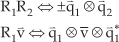
where
When a rigid body is rotating with an angular velocity vector

2.2 System model
In order to establish the dynamic equations of the quadrotor attitude system, coordinate frames must be establish first of all. This article uses two coordinate frames: an inertial coordinate frame and a body coordinate frame. As seen in Fig. 2, the origin of the body coordinate frame Ob – XbYbZb is located in the centre of the cross beam of the quadrotor: axis X pointing towards propeller 1, axis Z is perpendicular to the cross beam plane, and the three axis is to form a right-handed coordinate system.
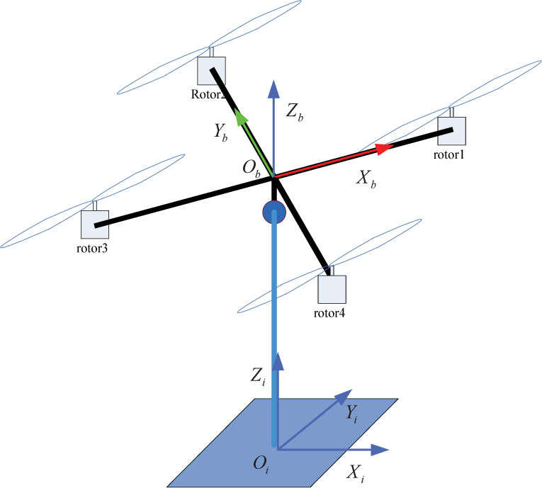
Coordinate frames of the quadrotor
The quadrotor dynamics are based upon two assumptions:
The quadrotor is a rigid body. Any small error in the manufacturing and installation of the vehicle body is not considered, so the quadrotor is assumed to be symmetric.
Based upon assumption one, the following mathematical model can be derived from the Newton-Euler equations and quaternion kinematics:
where
According to the second assumption, the correspondence between four propeller thrusts fi (i = 1,2,3,4) and the torque u(i = 1,2,3) acting on the quadrotor is given as follows:

where f is the total thrust and d is the distance between the propeller and the centre of the cross beam and cτf is the torque thrust ratio of the propeller.
Our model does not include the propeller gyroscopic torque and the flapping dynamic term; thus,

Considering the low-speed characteristics of the quadrotor, the following simplified equation is used to derive the propeller thrust [1]:

where cf is a constant coefficient.
3. Controller Design
The objective is to design a time optimal attitude controller under the limitations of input torque. In order to circumvent the difficulty of solving the Hamilton-Jacobi-Bellman (HJB) equation, the inverse optimal control approach is used. However, since the unit quaternion has four elements, it is difficult to implement the inverse optimal theorem directly. In order to simplify the design complexity, the backstepping technique is employed in the controller design procedure.
3.1 Inverse Optimal Theorem
The inverse optimal control approach is originated by Kalman to establish certain gain and phase margins of linear quadratic regulators. However, until Freeman uses the approach in [15] to develop a methodology for designing a robust nonlinear controller, it has been long dormant. In this section, only the main results of the approach are given, more detailed material and proofs can be found in [14–16].
Consider a control affine nonlinear system:

where u ∈ ℝn is a control input, and f(x) and g(x) are continuous function matrices.
Let V be a C1, proper, positive definite function V: ℝn → ℝ+, such that:
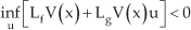
for all x ≠ 0. The existence of a CLF for the system (14) is equivalent to the existence of a globally asymptotically stabilizing control law u = k(x).
Assume that the static state feedback control law:
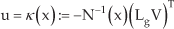
stabilizes the system in (14) with respect to a positive definite radially unbounded Lyapunov function V (x), where N: ℝn → ℝn is a positive definite matrix-valued function. Then the control law:
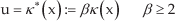
is optimal with respect to the cost:

where:

3.2 Backstepping-based Inverse Optimal Attitude Controller
The controller design procedures of backstepping can be divided into two phases:
Design a virtual control law to stabilize virtual quadrotor kinematics. Design the true control law which would be implemented on the system based upon the quadrotor dynamics and the virtual control law designed in phase 1.
3.2.1 Control of the Kinematics Subsystem
The kinematics subsystem in (10b) is controlled only indirectly through the angular velocity vector w, so the virtual system is considered:

where

Then the derivative of attitude error is:

Equation (22) can be rewritten as:

Consider a Lyapunov function candidate for the virtual system:

V1 ≥ 0 and V1 = 0 if and only if
The derivative of V1 is:

Here, sgn(·) is not a traditional sign function, and is defined as:

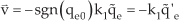
Let:

Then, we have:

Design the virtue control input as:
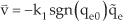
with any k1 > 0. Then:

It can be seen that V̇1 < 0 and V̇1 = 0 if and only if
After introducing the virtual control


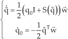
It is already known that the unit quaternion

where
3.2.2 Control of the Full Rigid Body Model
Consider now the angular velocity error:
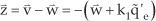
Then, the differential Equation (30) can be rewritten as:

Moreover, as shown above, it is asymptotically stable for
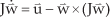
where:

We want to find
Let:
and:

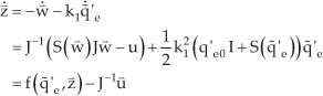
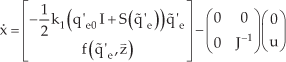
The system model can be rewritten as:
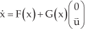
Since the derivative of the control Lyapunov function is:

Provided that applying the inverse optimal control theorem:

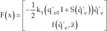
could make V̇(x) negative with a sufficiently high gain, then the maximum rate control law is given by:
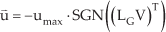
where umax represents the maximum value of input saturation.
Notice that the SGN function is an extended sign function for a multidimensional situation. Since the sign function can be seen as the direction function of one dimension, i.e.:

we extend it to a three dimensional situation, such as:

Consider the new Lyapunov function:

Then, the maximum rate control law (with respect to the designed Lyapunov function) is:

Notice that the backstepping-based inverse optimal controller (BIOAC) that we designed is a sliding mode controller with the sliding surface:

It has the inherent property of robustness as to matched model uncertainty and explicit disturbances. However, since the sign function SGN(·)will cause a high frequency oscillation in practice, the sliding mode control law will suffer the chattering problem. For removing chattering in sliding mode control, there are a few methods. A more common approach is to replace the sign function by a smooth function with a boundary layer of the form:

where ε is a constant vector to represent the boundary layer. However, with a boundary layer the BIOAC sacrifices the robustness in relation model uncertainty and explicit disturbances.
4. Numerical Simulation
In this section, the performance of the designed BIOAC is compared with a PD controller using numerical simulation in the MATLAB environment. The system parameters used in the simulation are:

The initial conditions are:

And the desired condition are:

This corresponds to the initial attitude errors of 161.7 degrees around axis (1,1,1)T.
For a more obvious illustration of control performance, the PD controller which provides a near-eigenaxis rotation [18] is used as a comparison. The PD algorithm is described as:

In the simulation process of the PD controller, the control effort limitation is never settled, and in a maximum rate control simulation the maximum control effort is (0.05N · m, 0.05N · m, 0.05N · m).
Appearing in the attitude quaternion curves in Fig. 4 and the output control torque curve in Fig. 5, the BIOAC is faster than the PD with a control effort under the maximum limitations. Moreover, the PD controller seeks a greater control torque when the error of orientation is large, and will suffer the problem of control failure in practice.

Time histories of the quaternion

Time histories of the control torques
5. Experiments
Given a good performance in the MATLAB simulation, BIOAC is realized on a test bench to show its effectiveness in practice. The physical device being used in the work discussed here is shown in Fig. 6. The experimental system consists of a posture platform, an aircraft body, an onboard controller, an attitude and heading reference system (AHRS), a wireless serial communication interface, a remote controller and receiver, and a computer.

Physical devices for the experimental system
The aircraft body selected is the XAircraft X-650 quadrotor, which is made of carbon fibre, equipped with four brushless DC motors and a motor speed control device. It has an empty weight of about 800g and the maximum single propeller thrust is 4N. The Attitude and Heading Reference System is the Xsens company MTi inertial measurement unit (IMU), which can provide 3 axes of driftless orientation and 3 axes of calibrated angular velocity. Its maximum update rate is 100Hz, with a 0.5 degree attitude measurement accuracy, a 1 degree heading measure accuracy, and a 300 degree per second maximum measurable angular velocity. The remote controller and receiver is a WFLY FT06-A with a 5-way continuous pulse channel and a switching channel. TI's TMS320F2809 chip with a 100MHz core frequency is the core of the onboard controller.
The connection diagram of experimental system signals is shown in Fig 7. In every control cycle (10ms), the F2809 chip is interrupted to receive orientation and angular velocity information from the IMU and then calculate the control pulse width and transfer it to the motor speed control devices. Outside the control loop, the F2809 is interrupted to turn the parameters and sends a set of state data to the computer in every 100ms. The work of receiving the remote control instruction is done in the same interrupter program.

Signal connection diagram
In the experiment, the attitude of the quadrotor switch is between:

and:

i.e., the quadrotor rotates 20 degrees around the axis of (1,1,1)T
In the experiment, J and cτf is unknown. However, since BIOAC is a sliding mode controller, it can work effectively with the settings of J = I and cτf = 1.
The attitude curves in Fig. 8 show that the controlled system is stable and, after the switch instruction, the attitude of the quadrotor converges to the desired attitude fast. There are small static errors in Fig. 8 and Fig. 9. The reasons for this are the incomplete compensation and the existence of the boundary layer. The results would be improved with a more accurate estimation of J and cτf.

Time histories of the quaternion

Time histories of the input instructions
6. Conclusions
The maximum rate attitude control problem of the quadrotor is studied under the constraint of input saturation. Due to the difficulty in obtaining closed-form solutions to the HJB equation, the inverse optimal approach is used. Following the backstepping phases, a global stable controller is derived. With respect to a classic PD controller, the numerical simulation results show that BIOAC could achieve faster convergence with control effort limitation. The realization of the BIOAC is gained in an experimental system and shows the practical effectiveness of being free from computational issues, which is highly desirable given the limited resources onboard.
7. Acknowledgements
The authors would like to thank Dr. HE Yunze in NUDT for providing advice and Dr. SHEN Tao and SONG Baoquan in NUDT for their help in constructing the test bench.