
Abstract
Abstract Autofocus is a fundamental and key problem for modern imaging sensor design. Although this problem has been well studied in single camera literature, unfortunately, little research has been done on large-scale camera arrays. Most of the existing synthetic aperture imaging systems still need to manually select the optimal focus plane when an object moves. Unlike the conventional autofocus method, which sweeps the focus plane to find the maximal contrast, we present a novel optimization framework to handle the above challenges. In particular, we formulate the camera array autofocus problem as a constrained optimization problem by minimizing the temporal and spatial correspondences error subject to global loop constraint. Then this problem is relaxed as a quadratic program and solved using sequential quadratic programming. The experimental results show that the proposed method achieves a better performance compared with the results of traditional methods. To the best of our knowledge, our proposed method is the first optimization framework for solving camera array autofocus problem and it is of great importance to improve the performance of the existing synthetic aperture imaging system.
1. Introduction
Autofocus (or AF) is one of the most important characteristics of an optical system. An intelligent AF system can adjust the camera lens to obtain focus on the subject so as to achieve sharpness at the focus point and is the foundation of many algorithms and systems in the fields of image processing, computer vision and pattern recognition.
By camera array autofocus, we mean that the relative position of the object to the camera array can be calculated automatically and thereby all the camera images can be accurately aligned on the object. It is obvious that this ability to continuously focus on the object dynamically is essential for the camera array to track a moving object robustly in occlusion cases.
Although single camera AF algorithms and systems have been well studied in the literature, to the best of our knowledge little work has been done on the camera array.
One difficult problem comes from the dynamic motion of the observed object; another problem comes from partial or even complete occlusion in multiple camera views.
In this paper, we propose a novel camera array autofocus (CAAF) model. Differing from previous works, our model for the first time integrates the spatial and temporal constraints of a large-scale camera array into a global optimization framework, which can be formulated as a quadratic program and solved via sequential quadratic programming. Extensive experiments with qualitative and quantitative evaluation demonstrate the accuracy, robustness and superiority of our approaches compared with state of the art AF algorithms.
The rest of the paper is structured as follows. We review work related to single camera AF and multiple camera AF in Section 2. In Section 3, we present both framework and details of our CAAF model. The challenging case of occlusion handling is discussed in Section 4. Extensive experimental results are given in Section 5, followed by conclusions and future work in Section 6.
2. Related Work
2.1 Single Camera Autofocus
Broadly speaking, previous single camera AF systems can be roughly classified into two categories: active AF systems and passive AF systems.
Instead of analysing the input image, active AF systems measure the distance to the observed object independently of the optical system. For instance, Polaroid cameras emit ultrasonic sound waves to estimate distance, while Nikon and Canon use infrared light to obtain the distance to an object. One drawback of an active AF system is that due to sound and infrared light reflection by the glass, the system usually cannot focus through windows and the accuracy of the focus is often considerably lower than that of passive systems. Another downside is the increased optical system complexity with additional multiple sensors.
Passive AF systems directly estimate the focus plane by analysing the image captured by the optical system without any assistance from other sensors. Typical passive AF methods include phase detection and contrast measurement. Phase detection is often used in single-lens reflex cameras and is achieved by dividing the incoming light into pairs of images and comparing them. Usually, the two images are analysed for similar light intensity patterns (peaks and valleys) and the separation error is calculated in order to find if the object is in front focus or back focus position.
Contrast measurement is performed by analysing the contrast of the input image. As the intensity difference between adjacent pixels usually increases with good focus, we can adjust the focus depth until the maximal contrast is detected. Since it does not use a separate sensor, this method can be more flexible and potentially more accurate. However this approach still has several defects. First, it cannot handle textureless objects with only one uniform colour. Second, it is sensitive to illumination and may fail under dim light. Third, local searching processing is needed to find the maximal contrast, which is generally very time-consuming.
2.2 Camera Array Autofocus
Among existing multiple camera techniques, recently the camera array has proven to be a powerful tool for seeing objects through occlusion. The pioneer work of synthetic aperture imaging is proposed by Levoy et al. [1]. They setup a two dimensional Stanford light field camera array which consisted of 128 firewire cameras and for the first time multiple cameras were aligned to a focus plane to approximate a camera with a very large aperture. The MIT computer graphics group [2] used 64 USB webcams to obtain dynamic depth of field effects. Wilburn et al. [3] used 100 custom video cameras to approximate a video camera with a large synthetic aperture. Synthetic aperture focusing [4–8] consists of warping and adding together the images in a 4D light field so that objects lying on a specified surface are aligned and thus in focus, while objects lying off this surface are misaligned and hence blurred. Veeraraghavan et al. [9] presented a novel design to reconstruct the 4D light field from a 2D camera image without any additional refractive elements as required by previous light field cameras. Liang et al. [10] introduced a system including a novel component called a programmable aperture and two associated post-processing algorithms for high-quality light field acquisition. The shape of the programmable aperture can be adjusted and used to capture light fields at full sensor resolution through multiple exposures without any additional optics and without moving the camera. Maître et al. [11] used a planar camera array to perform surface reconstruction. Lei et al. [12] developed a cluster-based system for camera array application, which consists of eight nodes and 16 cameras. Schuchert et al. [13] estimated the 3D object structure, motion and rotation based on 4D affine optical flow using a multi-camera array. Ding et al. [14] constructed a 3times3 camera array to recover fluid surfaces. Although camera arrays have been well studied in the literature, little work has been done on the problem of camera array autofocus. Most of the existing systems need “manual” adjustment of the focus plane. In SIGRAPH2006, Joshi et al. [15] took the lead on presenting a camera array “autofocus” algorithm. Their approach is similar to the contrast measurement of single camera AF, where a camera varies its focus and picks the setting that gives the strongest gradients in pre-defined regions. The measurement they used was the intensity variance, because low variance at a depth plane usually implies that a number of features are aligned and thus an object is present. They sweep a synthetic focal plane through the observed scene, sum the variance at each plane with nine focus regions and pick the depth that gives the minimum variance in one of these regions.
The first limitation of Neel's approach is that they assume the variance of the background is several orders of magnitude larger than that of the foreground so when this is not the case, this method will fail. The second limitation is that the foundation of this approach is based on low variance implying good focus, which is not valid since the variance of the foreground will be greatly increased under occlusion.
In contrast, we seek to continuously focus and see occluded objects even under object motion and occlusion, which is a general and difficult problem in the field of synthetic aperture imaging. Our main contribution is two-fold: first, we introduce a general camera array autofocus framework, which has the unique ability to continuously focus and see an object under challenging conditions. In this novel framework, very few parameters need to be adjusted and the problems of object motion and partial or even complete occlusion in several camera views can be naturally handled. Second, we demonstrate that the CAAF problem can be formulated as a constrained optimization problem and solved robustly by sequential quadratic programming.
3. Camera Array Autofocus Model
In this section, we first give the mathematical model of the CAAF problem. In the second step, three independent constraints are introduced, including a continuity constraint, a multi-view constraint and a global loop constraint. It is also shown that the calibration information of the camera array can be accounted for in multi-view constraints. Finally, the problem is formulated as a quadratic program and solved via sequential quadratic programming.
3.1 Formalization
As shown in Fig. 1, our algorithm takes a reference image and all the current camera images as the input. In this paper, the reference image is fixed and we simply choose the first frame of the fourth camera as the reference image. With the assumption that the object can be approximated as a planar object, our algorithm aims to estimate the object depth and the homography transformation with regard to the object between the reference image and all the cameras as well as between different cameras.

Homography constraint graph of the camera array. An example of global loop is visualized by the bold black line.
The transformation from each camera to reference image is represented as a temporal homography
We present a unified framework to obtain the optimal focus plane through global optimization of temporal and spatial homography wrappings inside and across different camera views. This optimization framework mainly consists of three independent constraints: a temporal local continuity constraint, a spatial multi-view constraint and a global loop constraint.
The first constraint comes from temporal local feature correspondences between the reference image and the current image, which enforces a constraint on the temporal homography of each camera individually. The second constraint stems from spatial feature correspondences between different camera views. It is shown in Section 3.3 that a simple spatial homography representation, which takes into account the specificity of the camera array, can be introduced to tremendously simplify the problem. The third constraint is based on the fact that temporal and spatial homography establish a loop between each camera pair and the reference image.
As can be seen from Fig. 1, the continuity constraint is a unary constraint on
Instead of solving this optimization problem using a Markov random field or other general optimization methods, we formulate this problem as a quadratic program. Specifically, the optimization problem is formulated as a constrained optimization problem by minimizing the temporal and spatial correspondence error subject to global loop constraints. Then this problem is relaxed as a quadratic program and solved using sequential quadratic programming.
The main advantage of this approach is that if a solution is found, it is guaranteed to be consistent with all the global loops, which makes the homography estimation result more stable as all the homography matrices are related together.
In this paper, the number C of cameras used is eight. For initialization, we specify the object depth and manually label the object on the reference camera. Therefore, the homography transformation between the reference image and all the individual cameras, as well as between different cameras can be directly calculated. For successive frames, we simply use the results of the previous frame to initialize these homography wrappings. All the correspondences inside or across different camera views are obtained by SIFT [16] feature matching.
3.2 Continuity Constraint
Our continuity constraint is defined between each camera and the reference image. By calculating corresponding feature points

where xit and xr0 represent the corresponding points in camera i and the reference image respectively. As Equation (1) is determined up to a scale factor, if there are ni point correspondences in

In this equation,
3.3 Multi-view Constraint
Except the feature point correspondences between each camera and the reference image, we can also establish correspondence within each camera pair. Suppose

where
Suppose homography projections on to the reference calibration plane and relative camera displacements with respect to the reference camera have been calculated with a plane+parallax calibration algorithm [16], we can get the following equation based on synthetic aperture focusing:
where
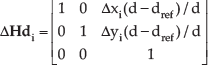
In this equation, Δxi and Δyi are the relative camera displacements in the x and y direction, dref and d mean the calibration depth and current depth. From Equation (4) and Equation (5), we have:

Thus,

So Equation (3) becomes:

It should be noted that Equation (4) is true only when all the correspondences are on the same frontoparallel plane. When this is not the case, we should compute corresponded
Similar to the discussion in Section 3.2, if there are ni,j correspondences between camera pair i and j, we have 2ni,j independent linear equations, all of which are about the object depth d.

where ci,j and bi,j are both 2ni,j × 1 vectors.
3.4 Global Loop Constraint
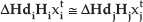
Our global loop constraint is a ternary constraint between
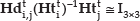
To avoid a matrix inverse operation, we rewrite Equation (10) as:

Equation (11) defines a set of eight polynomial constraints on
Differing from the above two constraints, which are either on each camera independently or on the depth of the object, the global loop constraint combines the camera homography and object's depth together. The main advantage of introducing this constraint is that the solution is guaranteed to be consistent with the camera array and the CAAF framework can still work well even if the object is severely occluded in the majority of cameras.
3.5 Sequential Quadratic Programming
As shown in Fig. 1, the estimation of

In other words:
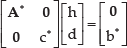
By gathering all the global loop constraints, we get:
Thus, it is natural to estimate Γ by solving:

However, as the constraints are not linear, the problem is not convex and therefore is difficult to solve. In this paper, we linearize the constraint in its neighbourhood and relax the problem as a sequential quadratic program.
Given an initial value Γ0, we propose to estimate Γk iteratively by solving the following quadratic program:

where ε is a small positive parameter. This quadratic program can be effectively solved with many off the shelf optimization softwares, such as GPLK and SeDuMi. In this paper, we use convex optimization software package CVX to solve this problem. Experiments show that the solution converges rapidly and a solution with satisfactory accuracy is usually found within five iterations.
3.6 Algorithm Output
Based on the output of our algorithm, we can easily perform a synthetic aperture focusing on the object. There are two different focusing methods, one is based on the estimated object depth and the other is based on homography mappings. More details will be discussed in Section 5.
4. Handing Occlusion
As mentioned in Section 3, one of the main advantages in our camera array focusing system is that it has the ability to see-through occlusion and track objects robustly even under severe occlusion. In this paper, the meaning of severe occlusion is two-fold. The first refers to cases where the object is partly occluded in all cameras, like the case when the object is occluded by a blooming tree. The second deals with cases where the object is totally occluded in some cameras. For instance, when the occluder is a moving person, the target may be totally occluded in some cameras while visible in others. Besides, this visibility information changes dynamically as the occluder keeps moving. Neither of these two cases has been successfully solved in single camera focusing or tracking.
What about the performance of our algorithm in these two challenging cases? It is obvious that occlusion only reduces the number of corresponded feature points we can use and does not influence our optimization framework at all. Specifically, the continuity constraint as well as multi-view constraint will be weakened, but the global loop constraint will always remain unchanged. As long as the object is visible to a certain degree in all eight cameras of the camera array, our framework will work quite well. Therefore, occlusion can be naturally overcome within our framework in the two mentioned cases. As a result, focusing and tracking can be performed robustly except in very extreme cases.
5. Experimental Results
5.1 System and Dataset
Since the existing public multi-view dataset does not satisfy the camera array autofocus requirements of our approach, to evaluate the performance of our algorithm, we have set up a linear camera array in our laboratory with eight Pointgrey Flea3 cameras (as shown in Fig. 2). The aperture size of this camera array is about one metre. The camera array is connected to a single data server via four PCI-E Firewire adaptors. Multiple view images are captured at a speed of 60fps with an image resolution of 640times480. The time synchronization accuracy of our system is less than 125 microseconds.

The layout of our camera array system
In this section, we present our results from three experiments. First, we test our autofocus algorithm on a planar image and a nonplanar human face with frequent object depth variation, large tilt and rotation. Comparison results with state of the art imaging methods (standard Synthetic Aperture Imaging [17]) are given respectively. Second, to demonstrate the advantages of our approach in handling occlusion, we ask several volunteers to walk in front of the observed moving object. Experimental results show that our approach is better than AutoFocusing [15] and can robustly solve partial and even complete occlusion in several camera views. Finally, to evaluate the tracking performance of our algorithm, we compare our method with several state of the art tracking methods, including: ContextTracker [18] and PNTracker [19]. Tracking results show that our algorithm outperforms other methods and can estimate the object focus plane accurately and track objects robustly even under occlusion.
Our main data set consists of 11 video sequences. Considering the possible surface depth variation of the object, the chosen objects for data acquisition include a planar image and a nonplanar human face. Additionally, complex scenarios with frontoparallel translation, forward and backward walking, large tilt and rotation, as well as severe occlusion are also included.
5.2 Autofocus Results with Depth and Pose Variation
We begin the experiment with a study of autofocus of a planar object. Fig. 3 and Fig. 4 show the autofocus comparison results of our algorithm with standard synthetic aperture imaging method [17].
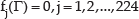
Comparison results of different camera array autofocus methods under large-scale change, translation, tilting and rotation. The first row is our synthetic aperture imaging result based on estimated depth, the second row is our autofocus result based on homography matrices, and the last row is the result of standard Synthetic Aperture Imaging[17]

Comparison results of different camera array autofocus methods under large-scale change, translation, tilting and rotation. The first row is our synthetic aperture imaging result based on estimated depth, the second row is our autofocus result based on homography matrices, and the last row is the result of standard Synthetic Aperture Imaging [17]
The test sequences consist of two handheld planar images. Fig. 3 shows the cover of the second edition of Multiple View Geometry written by Richard Hartley and Andrew Zisserman, which contains printed text and colourful circles. Fig. 4 shows the Bell Tower of Xi'an City, which is typically Chinese classical architecture. A volunteer rotates and tilts the planar image while walking inside the overlapping field of view of the camera array. These sequences test the ability of our autofocus algorithm to cope with planar object depth and pose variation.
In all cases our method is more accurate and the difference is especially large when the object moves far away from the initial focus plane. Please note that due to the spatial and temporal constraints and the global loop optimization, our method estimates the focus plane accurately under planar image movement, large rotation and tilting. In contrast significant blurs appear in the method of standard SAI [17] when the depth changes dynamically.
To further evaluate the effectiveness of our autofocus algorithm, we manually labelled the ground truth of the object depth in each frame. To obtain the ground truth-value of object depth, we performed standard SAI on sampled depths and select the one with best imaging result. In our test, the depth error of our algorithm is under 0.15m throughout the whole sequence, which is accurate enough considering the tilt and non-frontoparallel motion involved.
Next we apply our method to nonplanar face cases (as shown in Fig. 5). The data involves two human face sequences captured at shoulder level. The difficulty of this case comes from two parts. The first part is the depth variation of the nonplanar face surface, the second part is the unknown relative motion between the people and the camera array. Although strictly speaking, the planar homography transform assumption is no longer valid in this case, Fig. 5 shows that our algorithm still works well in spite of the depth variation of the nonplanar face surface. The reason behind this is that in our autofocus framework and homography transformation provide a good approximation when the depth variation is small a as a result of global optimization the solution is guaranteed to be consistent with the camera array.

Our synthetic aperture imaging results on nonplanar human faces
5.3 Autofocus Results with Occlusion
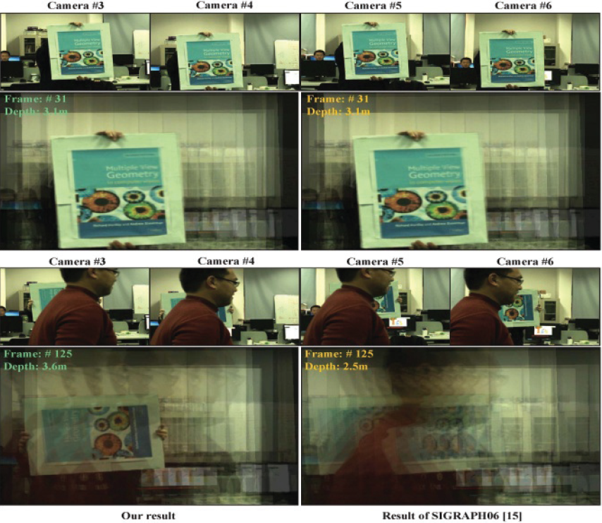
We then tested our algorithm under severe occlusion. As shown in Fig. 6, Fig. 7 and Fig. 8, there are three different test sequences. These test sequences contain frequent occlusion of moving handheld planar images. They are very challenging because not only do the objects contain large scale and rotation changes, but also they are partially or even completely occluded in several camera views.

Comparison of camera array autofocus results through occlusion (People occlusion sequence)
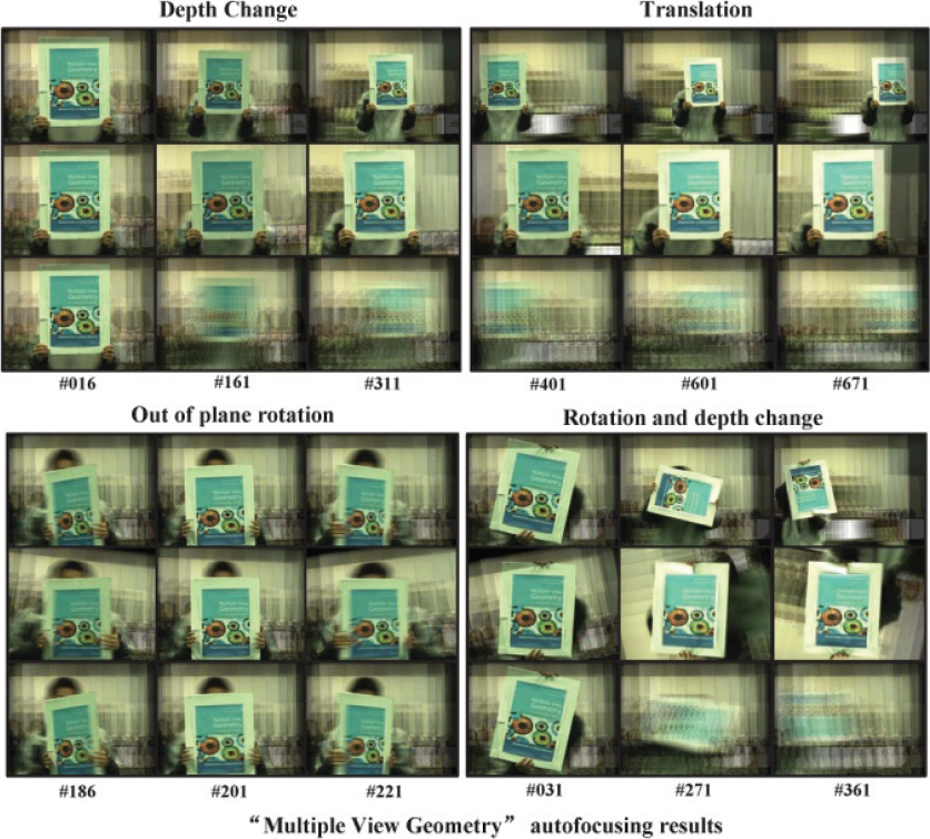
Comparison of camera array autofocus results through occlusion (Plant occlusion sequence)
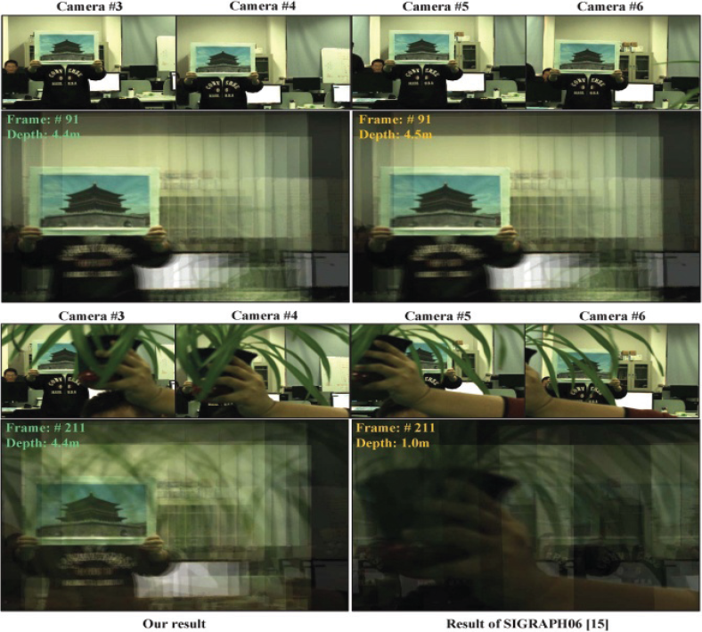
Comparison of camera array autofocus results through occlusion(Rotation and occlusion sequence)
Fig. 6 shows the case when the object is totally occluded by a person in several views while visible in other cameras. Fig. 7 shows the case when all cameras are partially occluded by foliage, while Fig. 8 is a more challenging sequence containing person occlusion as well as object pose changes. The first row of each subfigure displays the original input images of different camera views. The second row presents the comparison results of the AF method [15] and our method. Both AF and our method successfully focus on the moving object without occlusion in frame #37 (Fig. 6), #91 (Fig. 7) and #31 (Fig. 8). However, the AF method fails when there is severe occlusion, in frame #93 (Fig. 6), #211 (Fig. 7) and #125 (Fig. 8). This is not surprising as occlusion or object pose change violate the fixed window minimum variance principle of AF. However, our method accurately focuses on the object with rotation, depth variation and occlusion. The better performance of our method comes from the fact that occlusion only reduces the number of matched feature points and has no influence on our global loop constraint. As long as there exists a valid loop in the camera array, our algorithm can still estimate the depth and homographies accurately. It is shown that good depth estimation results can be achieved in our global optimization framework. Please note that half of the camera views are completely occluded in frame #101 (Fig. 6) and #125 (Fig. 8) and our algorithm still focuses on the object focus plane accurately.
5.4 Comparison Results of Visual Tracking
Perhaps one of the most likely applications of our method is visual tracking. Due to the advantages of see-through occlusion, the camera array has proven to be a powerful tool in tracking, especially in occlusion cases. In our autofocus framework, tracking is performed naturally. Based on the homography wrappings between each camera and the reference image, we can easily calculate the tracking bounding box of the object on each camera as well as on the synthetic aperture image. In order to evaluate the tracking performance of our algorithm, we use several state of the art tracking methods for comparison, including the TLD tracker and Context Tracker (CT). All codes are from the original authors.
Tracking results from two difficult occlusion sequences are shown in Fig. 9 and Fig. 10 respectively. Fig. 9 is a static object under occlusion, while Fig. 10 is a more challenging case with occlusion as well as object rotation. The first row of each subfigure gives comparison tracking results from the reference camera and the second row shows the corresponding autofocus imaging results of our method. It is shown in Fig. 9 that when there is no occlusion, all three methods successfully track the object. However, when occluded by a front person on the reference image, the tracking accuracy of the single camera trackers decreases rapidly, while our method remains stable and robust throughout the whole sequence due to the proposed camera array global optimization framework. In Fig. 10, when the object is rotated rapidly, PNTracker (red rectangle) and Context Tracker (green rectangle) fail simultaneously. However, in contrast our algorithm accurately tracks the object (blue rectangle) stably, even in the most challenging cases (with occlusion and object rotation, as shown in frame #121).

Comparison results of tracking through occlusion

Comparison results of tracking through occlusion
5.5 Discussion of Processing Speed
The most time consuming part of our algorithm is establishing point correspondences and the sequential quadratic programming (SDP). In this paper, we use SIFT features to establish correspondences inside or across different camera views and the iteration times of the SDP is fixed as three. In this case, the running time of our algorithm is two seconds per frame with unoptimized Matlab code.
6. Occlusions and Future Work
Although the autofocus problem has been well studied for single cameras, little work has been done on large-scale camera arrays. In this paper we present a novel camera array autofocus framework which can estimate the optimal object focus plane dynamically and tracks objects robustly even under severe occlusion. The effectiveness of our approach benefits from global optimization based on the three constraints about the camera array introduced in this paper. To evaluate the proposed method, we have set up an active camera array.
Extensive experiments carried out on different objects and scenarios demonstrate the robustness, accuracy and efficiency of the proposed approach. As no visibility information is utilized to help segment the object in our framework currently, in future work, we plan to improve the imaging result and solve the occlusion problem by introducing a visibility analysis method into our framework.
7. Acknowledgments
We are very appreciate to the editor and anonymous reviewers for the time spent and valuable suggestions. This work is supported by the National Natural Science Foundation of China (No. 61272288, No.60903126, No.61231016), NPU Foundation for Fundamental Research (No.JC201120), Soaring Star of Northwestern Polytechnical University (No.12GH0311), the China Postdoctoral Science Foundation Special Class (No.201003685), and the China Postdoctoral Science Foundation (No.20090451397).