
Abstract
Robotic manipulators on a moving base are used in many industrial and transportation applications. In this study, the modelling of a RRP SCARA-type serial manipulator on a moving base is presented. A Lagrange-Euler approach is used to obtain the complete dynamic model of the moving-base manipulator. Hence, the dynamic model of the manipulator and the mobile base are expressed separately. In addition, Virtual Instrumentation (VI) is developed for kinematics, dynamics simulation and animation of the manipulator combined with the moving-base system. Using the designed VI in LabView, the relationship between frequency of disturbances of the moving base and joint torques is investigated. The obtained results are presented in graphs.
1. Introduction
Robotic manipulators utilized in many industrial and transportation applications, such as in underwater vehicles, space vehicles and surface ships, can be attached to moving bases. These manipulators are affected by disturbances of the moving base. For example, manipulators attached to the surface of a ship are affected by the motion of the sea. Underwater vehicles are placed under additional forces produced by flow dynamics and frictional effects. The manipulators used in space research are affected by variable gravitational forces. These undesirable disturbances have an important effect on motion and make it difficult to control the manipulator [1, 2].
It is necessary to develop a complete dynamic model for robotic manipulators attached to a moving base in order to increase the quality of control. For some applications, such as spray painting, it is necessary to move the end effector of the manipulator along some desired paths with prescribed speed. To achieve this goal, certain dynamical equations must be determined including the parameters from the fixed base to the end effector. These equations are applicable for fixed-base manipulators, but we are obliged to adopt these equations for moving-base manipulators, too, in order to avoid target tracking errors in the end effector. Therefore, the motion of the manipulator mounted on the moving base should be described by a complete dynamic model. There are a lot of studies in the literature which take account of moving bases in dynamic modelling and control algorithms [3, 4, 5, 6]. A dynamic model of a 1-DOF robotic manipulator on a moving platform is presented in [7]. A dynamic model of a robotic manipulator base is derived in [8] and used for simulation of a 2-DOF robot on a 3-DOF base. Computational methods to simulate a manipulator mounted on an underwater vehicle are presented in [9].
In this paper, a SCARA RRP (Revolute Revolute Prismatic), a manipulator with three degrees of freedom, was mounted on a two-degree-of-freedom mobile base. Kinematic analysis of the manipulator carried out first by using Denavit-Hartenberg (D-H) parameters. Then, the general dynamic model was developed for the manipulator and mobile base using a recursive method including all of the parameters. These models of manipulator and mobile base were obtained by using Lagrangian dynamics and the Mathematica program, because of the complex structure of dynamic models. Finally, the obtained dynamic equations were adapted in the LabView program and the simulation results were obtained. Using the LabView environment to simulate the considered system with the aid of the dynamic model derived is the main contribution of the present study.
LabView is a graphical programming language produced by National Instrumentation. It has been widely adopted throughout industry and academia as a standard for instrument control and data analysis simulation software. LabView also provides scientists and engineers with interactive programming for system design and control. The advantage of utilizing LabView is that it provides a powerful and flexible instrumentation and data analysis software system. LabView not only helps reinforce basic scientific, mathematical and engineering principles, but also allows communication with the real world.
The LabView program consists of two windows, the front panel and the block diagram. The block diagram is the LabView programming code. Its large libraries can be used to write a program. The front panel is an interface of a designed VI and includes knobs, switches, meters, graphs, charts, etc. The LabView program provides an interaction between supplying inputs and observing outputs [10].
In this study, a Virtual Instrumentation (VI) is built for kinematics, dynamics, simulation and animation for supporting the manual calculation of a three-degree-of-freedom SCARA-type robot and a two-degree-of-freedom mobile base. The designed VI can simulate visual movement of the SCARA robot and mobile base.
The organization of the rest of the paper can be summarized as follows: In section 2 the modelling of a SCARA-type manipulator robot with three degrees of freedom is presented. General dynamic models of the manipulator and mobile base are presented in section 3. The designed VI and simulation results are discussed in section 4. Finally, concluding remarks are given in section 5.
2. SCARA-type Manipulator
In general, a traditional SCARA-type serial manipulator consists of three interconnected joints. These manipulators are commonly used in pick-and-place, assembly and packing applications in industry and transportation [11, 12].
Especially when these manipulators are used in areas such as space exploration and shipping, the degree of freedom of the manipulator is increased due to the moving base. Fig. 1 shows a schematic of a SCARA-type manipulator and its mobile base.

Schematic of a SCARA-type manipulator and mobile base
2.1. Kinematics analysis of manipulator
In order to obtain the kinematic model, we define the below-listed frames, matrices and vectors as shown in Figure 1.
O: Fixed base frame attached on base of manipulator.
I: Inertial base frame.
As shown in Fig. 1, the SCARA-type manipulator has three joints which are linked to the robot. Joint 3 is a translational joint which can move along the z-axis, while joints 1 and 2 are rotational joints. For the coordinate systems shown in Fig. 1, the corresponding link parameters are listed in Table 1. In addition, the parameters of the manipulator are tabulated in Table 2.
Parameters of SCARA manipulator

Denavit-Hartenberg parameters of SCARA manipulator

By applying the homogeneous transformations given by Eq. (1), one obtains the kinematic model given by Eq. (2):
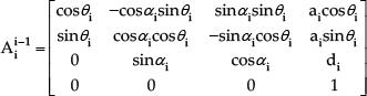

It is necessary to describe the manipulator's fixed base frame position and rotation relative to the inertial frame. Therefore, we should determine the end effector's position and orientation relative to the inertial frame.
By considering the rotation of the manipulator's base frame in relation to the inertial frame, the homogeneous matrix can be stated as a rotation of the frame about the X I axis by angle α, followed by a second rotation of β about the Y I axis and, additionally, a constant translation (P) along the X I axis by Eq. (3).

3. General dynamic models of manipulator and mobile base
After carrying out the kinematic analysis of the manipulator we can obtain its dynamic model by employing the Lagrange-Euler formulation based on the principle of energy conservation [13, 14].
If the 3-DOF SCARA-type manipulator has three generalized coordinates and the mobile base has n generalized coordinates, the total generalized coordinate of the system will be (3+n) due to the inertial frame. In this study, we assume that α and β are redundant coordinates; hence, the total generalized coordinate number of the system will be equal to five (q i =θ 1 , θ 2 , d 3 , α, β).
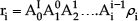
The position of a point on the centre of mass of link i relative to the inertial frame is given by Eq. (4):
As each generalized coordinate is a time function, the velocity vector can be expressed as

The kinetic energy for a single point of mass, dm, can be defined as

where tr is matrix trace.
After substituting Eq. (5):

The total kinetic energy of the links is given by integrating over the mass for each link and then summing as follows:


The integral of the term

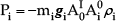
The potential energy of link i is written as
Kinetic and potential energy equations of the mobile base are given by Eq. (12):


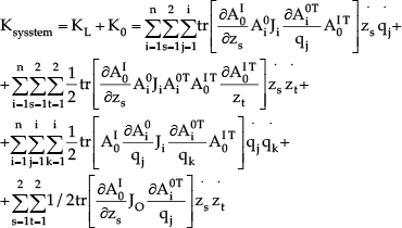
Thus, the total kinetic energy of the manipulator-base system is written as

3.1. Lagrange-Euler Formulation
The equations of motion for a manipulator mounted on a mobile platform are

where p i is the generalized coordinate and τ i is the generalized force or torque at joint i. Then, Lagrangian function becomes

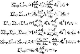
Using this Lagrange function and its derivative one may obtain the dynamic equations for the manipulator mounted on a mobile platform (Eq. 16):
p=1 gives the torque equation for link 1;
p=k gives the torque equation for link k.
Solutions of these mobile manipulator equations are performed with Mathematica, and the dynamic equations are transformed into matrix form.
Hence, the dynamic model of a manipulator and mobile base can be expressed through Eq. (17):

M: inertia matrix;
C: vector of centrifugal and Coriolis Forces;
G: vector of gravitational force;
3.2. Platform Trajectory
For simplification of the mobile platform simulation model, only roll and pitch motion will be considered.
The following type of disturbance of the mobile base is used to evaluate the model:
Roll or pitch motion sine trajectory

As is well-known from basic calculus, a sinusoid has different slopes in all points of the graphics. For this reason, a sinusoidal trajectory selection will be suitable to show dynamic behaviour of the system for different operating points.
4. The designed VI in LabView and simulation results
A graphical solution for calculating, simulating and animating the robot kinematics, dynamics and moving is implemented in a Virtual Instrumentation (VI) of LabView. Using the designed VI, one can simulate and animate online kinematics and dynamics of SCARA-type manipulators and different types of disturbances of the mobile base.
Figures 2 and 3 show the designed VI in a LabView block diagram and the front panel for a RRP SCARA-type manipulator on a moving base, respectively.

LabView front panel for RRP SCARA-type manipulator

LabView block diagram for RRP SCARA-type manipulator (animation block)

LabView block diagram for RRP SCARA-type manipulator (moving base trajectory block)

LabView block diagram for RRP SCARA-type manipulator (kinematic and dynamic calculation block)
As shown in Figures 2 and 3, the VI is used to move the manipulator by applying mathematical expression of kinematics and dynamics. To monitor joint trajectories, joint torques and moving-base trajectories, various indicators are located on the front panel. Amplitude, phase and period knobs are used to set values for the roll and pitch of the moving base. In addition, the cubic and high order polynomial joint trajectories options and 3D animation screen are on the front panel.
4.1. Simulation results
In order to examine the system, the cubic order polynomial joint trajectories have been considered. At the initial location, the manipulator is assumed to be located at P1=[θ 1 =0, θ 2 =0, d 3 =0]. For the final location, the manipulator moves from P 1 to P 2 , located at P 2 =[θ 1 =2pi/3 (rad), θ 2 =pi/3 [rad], d 3 =0.3 (m)] in 10 seconds. Firstly, inverse dynamic analysis of the SCARA-type manipulator is simulated without taking into consideration disturbance of the moving base. In the first instance, Roll and Pitch angles are both selected as 0. For this case, joint trajectory and actuating torques of joints are presented in Fig. 4

Trajectories of joint

Actuation torques for joint-1 and joint-2 (Roll&Pitch=0)

Actuation torque for joint-3 (Roll&Pitch=0)
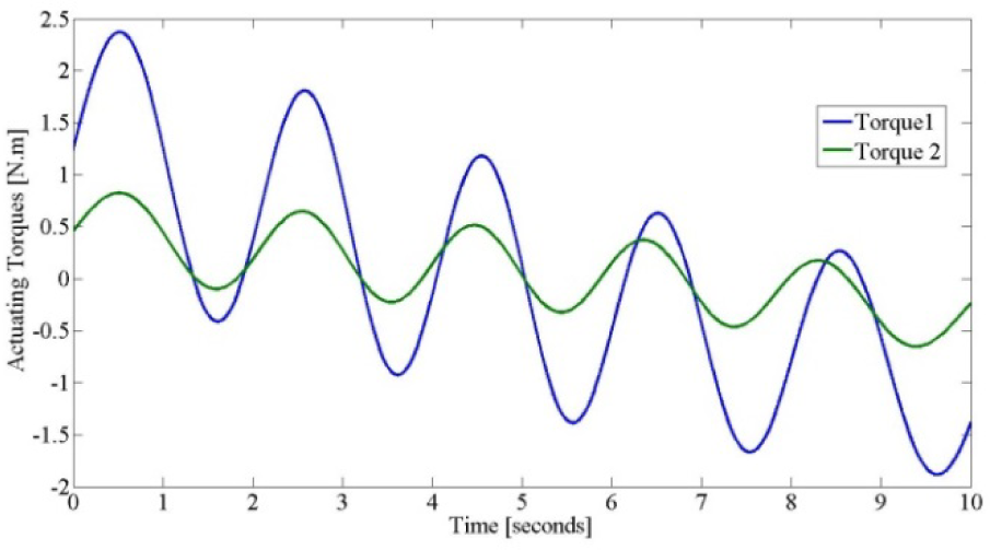
In order to exhibit dynamic behaviour of the system for different operating conditions, the second trial is divided into three subsections. Three types of disturbances of the mobile base are used to evaluate the dynamic model. Firstly, it is assumed that the moving base rotates about the x-axis with a function of sine as written in Eq. (18) (γ). The second assumption is that the moving base rotates simultaneously about the x- and y-axes with a function of sine as given in Eq. (18) (

Actuation torques for joint-1 and joint-2 (

Actuation torques for joint-3 (
Actuation torques for joint-1 and joint-2

Actuation torques for joint-3
Finally, in the third trial, the moving base rotates simultaneously about the x- and y-axes with a higher disturbance frequency, as stated in Eq. (18) (

Actuation torques for joint-1 and joint-2

Actuation torques for joint-3
When Figs. 5, 6 and 7 are compared with Fig. 4, more sinusoidal oscillations on the joint torques are observed, associated with increased frequency of roll and/or pitch disturbances. As is well-known, these oscillations that have occurred on the joint torques affect the actuators of the manipulator as a disturbance. When the frequency of disturbance is further increased, performance of the manipulator will decrease. The reason for this decrease in performance is that achievable performance of the manipulator is limited, in practice. The saturation and flexibility effects are the main limitations. Not only the mechanical structure of the system, but also the mechanical time constant of the used motor are therefore vitally important.
5. Conclusions
This paper has presented a generic model of a robotic manipulator on a moving base. Kinematics and dynamics equations of the RRP SCARA-type serial manipulator on a 2-DOF platform have been obtained. The derived equations have been simulated in the LabView program.
Inertial, Coriolis and centrifugal effects of the moving platform on the manipulator dynamics have been investigated. It has been confirmed graphically and numerically that redundant forces occur on the joint torques due to these effects. These forces cause deviation from the target trajectory of the manipulator's end effector.
With this developed approach, it is shown that the disturbance effects caused by the moving base can be added to the manipulator's dynamic model and expressed mathematically. Also, when the frequency of disturbance is increased, more sinusoidal oscillations on the actuating joint torques are observed.
6. Preliminary experimental setup and future works
The movement of a SCARA-type manipulator can be observed using a preliminary experimental set-up as shown in Figure 8.

Preliminary experimental set-up
As shown in Fig. 8, the disturbance effects on a manipulator base can be measured using a gyroscope sensor (for example, a Sparkfun 6-DOF Inertial Measuring Unit).
Gyroscopes are physical sensors that detect and measure the angular motion of an object relative to an inertial frame of reference.
The roll and pitch angle values that are obtained from the gyroscope sensor can be transferred to the computer using a data acquisition card (DAQ-NI PCI 6259).
Data acquisition (DAQ) is the process of measuring an electrical or physical phenomenon with a computer. A DAQ system consists of sensors, DAQ measurement hardware, and a computer with programmable software.
In this way, researchers can simultaneously observe joint torque variations of this manipulator and disturbance of the mobile base using this designed VI in LabView in real time. Also, they can develop a model-based control algorithm using the obtained complete dynamic model of SCARA-type manipulators. The minimum technical requirements to ensure the ability to run this VI are tabulated in Table 3.
Minimum technical requirements to run VI
