
Abstract
Abstract This paper addresses the problem of real-time vision-based human tracking to enable mobile robots to follow a human co-worker. A novel approach to combine stereo vision-based human detection with human tracking using a modified Kalman filter is presented. Stereo vision-based detection combines features extracted from 2D stereo images with reconstructed 3D object features to detect humans in a robot's environment. For human tracking a modified Kalman filter recursively predicts and updates estimates of the 3D coordinates of a human in the robot's camera coordinate system. This prediction enables human detection to be performed on the image region of interest contributing to cost effective human tracking. The performance of the presented method was tested within a working scenario of a mobile robot intended to follow a human co-worker in indoor applications as well as in outdoor applications.
1. Introduction
Human detection and tracking has been extremely active research area in the computer vision community over the past decade. The importance of this area arises from its numerous applications such as video surveillance, smart vehicle and virtual reality [1]. One of the broadest application areas is robot vision [2]. Vision-based human tracking is crucial for human-robot interaction in numerous human-centred robot applications. A person-following robot finds a specified person using visual tracking functions and follows him/her in order to provide different services for a human or to accomplish different tasks depending on the application [3]. Person following robots developed until now use various types of cameras for detecting a target person and some of them use other sensors in combination with vision. For example, in [3] a stereo vision system and additionally a Laser Range Finder (LRF) are mounted on the robot body to enhance the performance of the person following robot's behaviour. Furthermore, some authors developed methods including human-body wearable sensors [4], which are however, inadequate in some applications. In order to avoid the complex data fusion algorithms necessary in the case where different sensor types are used and in order to avoid human contact sensors, a number of authors have developed methods based on vision as the only sensor.
Although people detection and tracking with a single camera is a well-explored topic, it has been shown that detecting humans from a single image while maintaining a low false detection rate is a very difficult problem [5]. The use of stereo vision provides a higher grade of information that brings several advantages when developing human-robot applications. The information regarding disparities becomes more invariable to illumination changes than the images provided by a single camera, which is a very advantageous factor for environment estimation. Furthermore, the possibility of knowing the distance to the person could be of great assistance in tracking. The robot calculates the distance between the target person and itself using stereo vision and follows him/her with the appropriate speed to maintain the distance. In [6] a robust human detecting and tracking system, which can be used in indoor environments, is presented. Besides this there are numerous other human tracking methods applicable to indoor applications, which are based on background subtraction and on detecting the skin colour of the face and hands on a captured image. In contrast to these methods, in this paper a stereo vision-based human tracking method that can be used in both, indoor and outdoor applications is used. It is achieved by using only 3D information for human detection and tracking, disparity (depth) information for segmentation of object regions in the scene and 3D human characteristics extracted from a disparity image for human detection.
This paper also addresses the need for a fast vision module and distributed system architecture to enable real-time robot motion control. Such an open robot controller architecture connecting a number of software modules easily, including target detection module and robot motion control module, even if these modules are located on different computers, has been presented in [3]. In this paper, a realization of distributed processing using the ROS (Robot Operating System) [7] is considered. Support of time critical robot control is also achieved by a cost effective vision module for human tracking. This is achieved by implementing the Kalman filter as usual in vision-based human tracking [2], yet here the goal is performing human tracking on the image region of interest (ROI), rather than on the whole disparity image.
The remainder of the paper is organised as follows. Section 2 presents the layout of the vision-based robotic human follower system. Section 3 presents the first part of the vision module of robotic follower: stereo vision-based human detection. The second part of the vision module of the robotic follower; human tracking based on a modified Kalman filter, is presented in Section 4. The performance evaluation of the presented stereo vision-based human tracking within the working scenario of a mobile robot intended to follow a human co-worker in indoor applications, as well as in outdoor applications, is presented in Section 5.
2. Vision-based robotic human follower – system layout
The presented vision-based human tracking system is supposed to provide sensor input for vision-based control of a mobile robot, which works in a team helping a human co-worker with transportation of different objects in indoor applications, as well as in outdoor applications, such as investigation of a hazardous environment. For example, in the robot working scenario of investigation of contaminated/hazardous environments, the robot works as a transportation robot, helping the human to carry containers with collected samples from the environment. The vision system for human tracking within such robot working scenarios has to be able to detect the human, calculate the distance to the human and track the human, keeping a constant distance between them. After sensing the reduction in distance, indicating the human's intention to approach the robot, the robot has to stop and allow the human to place the containers with the collected samples onto the robot's mobile platform. The principal layout of the visually controlled robotic system for human tracking, whose vision module is described in this paper, is shown in Figure 1.

Principal layout of the robotic system for following a human co-worker.
The presented robotic system has a stereo camera system on board, as well as a low-power industrial PC (Intel i7-620M @ 2.66 GHz, 4GB of RAM, 64 GB SSD, ˜65 Watt). As the platform is intended to run on batteries so as to move independently of external power supplies, low power consumption of the on-board components is critical. Therefore, the on-board PC functionality is limited to capturing images from the stereo camera and sending them compressed over the wireless link to the off-board vision module, as well as sending direct commands obtained from the robot control to the wheel controllers.
In order to assure the control commands are sent at regular time intervals, the vision module and the robot control module run on different PCs, as illustrated in Figure 1, with differently coloured blocks. The computationally expensive vision algorithms run on a dedicated high-end PC (Intel Xeon E5520 @ 2.26 GHz, 6GB of RAM) with the goal of tracking the human co-worker in front of the robot and determining its 3D position with respect to the coordinate system of the left stereo camera, as depicted in Figure 1. The obtained 3D position is then sent to the robot control module located on a different desktop, PC (Intel E4700 @ 2.6 GHz, 2GB of RAM), which computes the required velocities for each wheel such that the robot keeps following the human. These velocities are then sent at regular time intervals over the wireless link to the on-board PC, which sends direct commands to the wheel controllers. If the robot control module ran on the same PC as the vision module, it might not be able to send the new velocities out in time due to the vision module blocking the CPU (Central Processing Unit).
The communication between the three computers is carried out via the ROS (Robot Operating System), which is a widely used communication framework that, among other features, allows easy configuring of multiple computers for cooperation in order to improve the time effectiveness of the system. This time effectiveness is achieved by splitting computationally expensive tasks into modules, which run on different computers.
The focus in this paper is on the robot's vision module. It consists of two sub-modules: stereo vision-based human detection and human tracking based on a modified Kalman filter.
3. Stereo vision-based human detection
A block-diagram of the presented human detection system is given in Figure 2 and the individual processing steps are explained in the following sections.
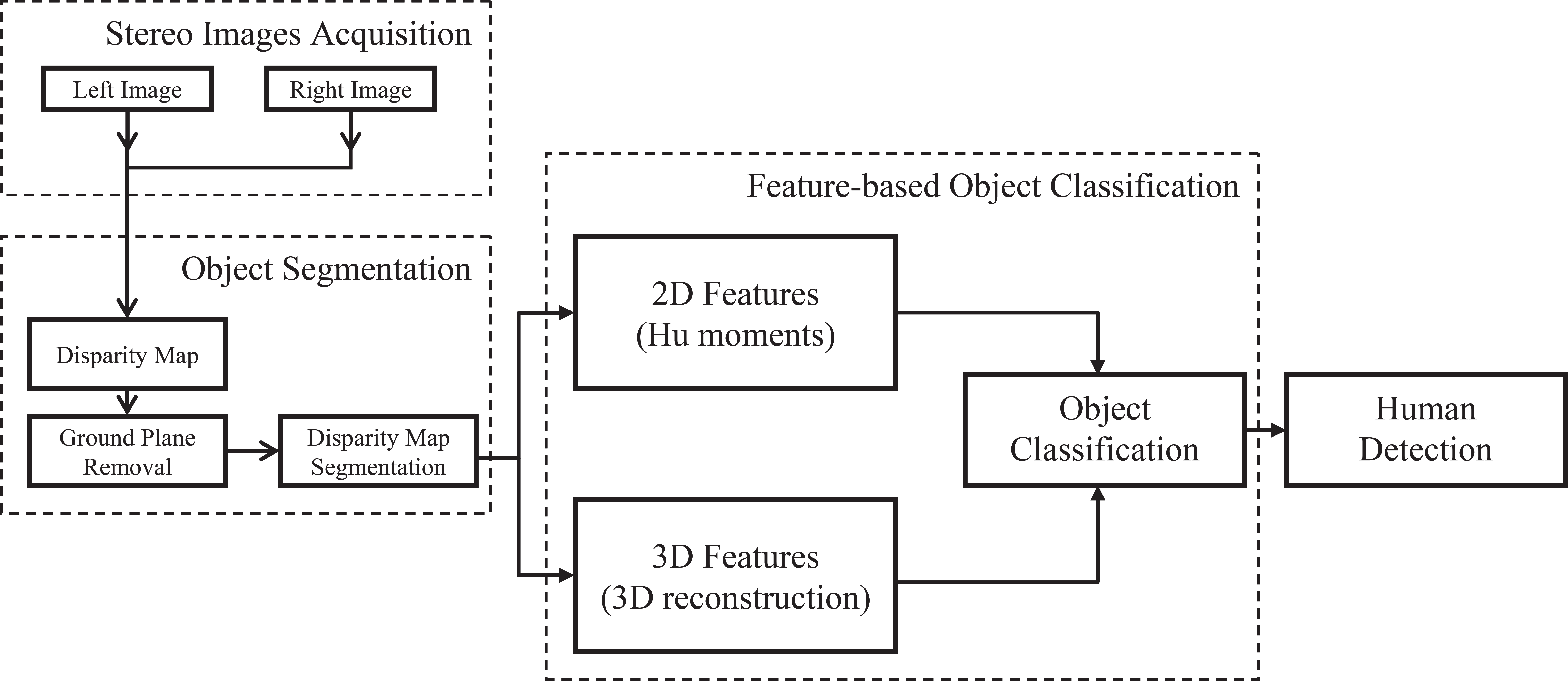
Block diagram of the proposed stereo vision-based human detection.
3.1 Object segmentation
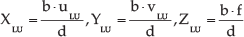
Stereo image information is used to aid the definition of regions of different objects, including humans, in camera images. The acquired image pair is used to compute a disparity map using a block-matching algorithm [8]. In principle, the disparity map is found by computing the stereo correspondences between the image points from the left and right stereo images. For a given 3D point P(X, Y, Z), the corresponding points in the left and right image respectively are pL(uL, vL)and pR(uR, vR), where u and v are coordinates of an image point in the image coordinate system with the origin in the camera's optical centre. The difference in u coordinates of corresponding points in stereo images is known as disparity d.

The disparity of an image point is inversely proportional to the distance of the original 3D point to the camera coordinate system known as depth. The resulting disparity map represents a 2D image in which values of pixels are equal to the disparity (1). The pixel coordinates in a disparity map correspond to the pixel coordinates in the left stereo image as the left stereo image is usually considered as the reference image when building the disparity map.
The resulting disparity map in the proposed system is segmented using a connected pixel labelling-based method. The main idea behind this segmentation method is to group the pixels with the same or very close pixel values as it is assumed that they belong to the same object. Namely, neighbouring pixels in the disparity map belonging to the surface of an object have close disparity values, while on the edges of the object the difference in disparity values between the pixels of the object and of the background is large. These transitions in disparity values are used for the segmentation. The details of the disparity map segmentation method used are given in [9]. The segmentation result in the case of the human tracking robot scenario considered here is shown in Figure 3(c). Differently coloured regions in the image in Figure 3(c) represent different objects, which are at different distances to the robot's camera. As can be seen, the ground has been removed from the segmented image (represented by black colour) in order to avoid merging with other objects, including humans, placed on the ground. The ground plane removal was done by detecting the regions in the lower part of the disparity map whose disparity values gradually change, i.e., whose image gradient in the vertical direction gradually changes. In contrast to ground plane pixels, in the disparity map the regions of object surfaces have almost constant disparity values.

Left stereo image of human walking in front of the robot (a). Disparity map (b). Segmented disparity map (c).
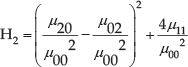
3.2 Feature-based object classification
Once the objects have been segmented in the disparity map, different features describing segmented object regions are calculated. The chosen features have been defined so as to enable distinguishing of humans from other objects in the robot's perceived environment. The used features can be separated into two groups: 2D features and 3D features. The former are calculated from the 2D segmented image, while the later result from 3D object reconstruction.


The defined features are used in the proposed system for the classification of an object as belonging or not belonging to the class “human being”. The used classifier is Backpropagation Neural Network with one hidden layer [12]. The training of the classifier, i.e., the neural network parameters adjustment, was done using a training set of 577 feature vectors (H1, H2, H3, h,w) extracted from segmented human regions in disparity maps of stereo image pairs acquired indoors as well as outdoors. The testing of the developed classifier was done using another 423 feature vectors. These test features were obtained by extraction from segmented regions of different objects, including humans, in disparity maps of stereo image pairs acquired indoors as well as outdoors. The obtained classification result from the training set was very good, as indicated by the fact that the classification performance rate was 96%. Misclassification, i.e., the inability to classify an object from a robot's environment as human, happened in cases of significant human occlusion or segmentation of humans as connected to objects from the environment. This indicates a need for integrating a module to predict and estimate the 3D position of the human to provide an input to robot control, even in the case of human classification failure. In the proposed system such a module is the modified Kalman filter described in Section 4.
3.3 Human detection
The last processing step in the proposed vision system is human detection. Once the human has been successfully classified, his/her 3D position with respect to the coordinate system of the left stereo camera is calculated through the 3D coordinates of the centre of mass of the segmented human region (ūHC, v̄HC) in the segmented disparity map:

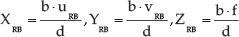
Besides the 3D coordinates (9), the outputs of the human detection module are also the 3D coordinates of the corner points of the human bounding box that are calculated according to (6) and (7), so that the final output of human detection is the nine-dimensional vector:

The 3D coordinates of the corner points of the human bounding box are further used by a tracking module. The tracking module is based on a modified Kalman filter and recursively predicts the estimates of the 3D coordinates of corner points, allowing the prediction of a region of interest (ROI) in the robot's camera images. This prediction enables human detection to be performed on the image region of interest rather than on the whole image, contributing to the cost effectiveness of human tracking as very important for robot control.
4. Human tracking based on a modified Kalman filter
4.1 Tracking system overview
Human tracking starts after N video frames have been used for the initialization of tracking based on a modified Kalman filter. N is the number of the first N consecutive frames in which human detection was successful. The presented application assumes one human co-worker in the robot's environment. However, the presented method is applicable also in cases where there is more than one human in the robot's environment. In that case, the first detected human (or the human closest to the robot) in the initialization phase is selected as the person to be followed and he/she is tracked in the tracking phase. In this way, even if other humans enter the scene, the robot is able to continue tracking the person selected for tracking in the initialization phase. In order to fulfil this task, the tracking system works under the assumption that the 3D position of the tracked person cannot suddenly change between two consecutive frames and therefore it is able to correctly locate the selected person in successive frames. This holds as long as the humans in the scene can be clearly distinguished from each other. However if one of the humans temporarily occludes the human selected to be tracked, he/her is not in the field of the camera's view anymore, but the proposed modified Kalman filter continues to predict his/her position, as explained in the following.
As illustrated in Figure 4, the stereo vision-based human detection is firstly applied to the whole image of the first N stereo image pairs to obtain human detection vector
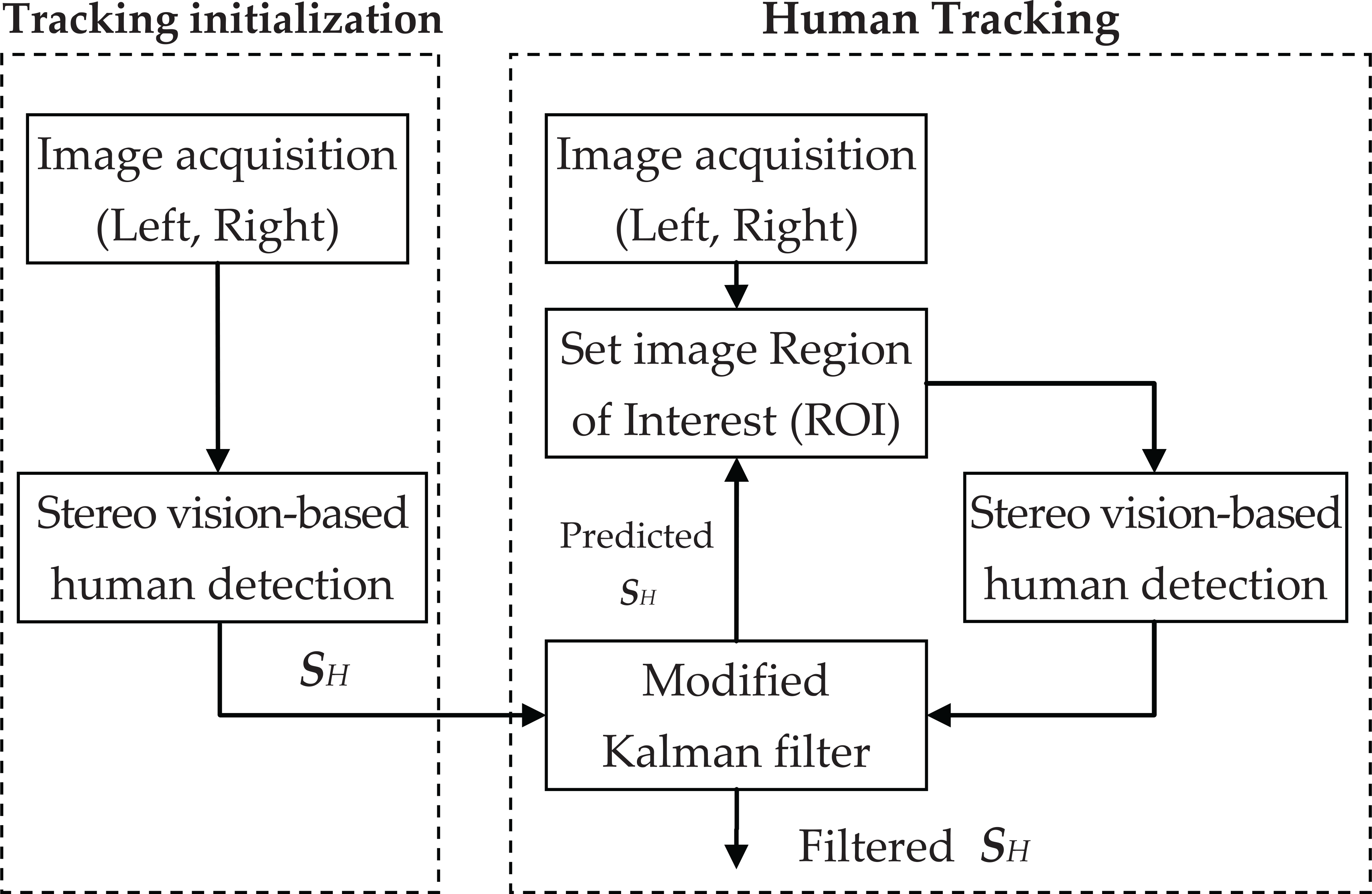
Block-diagram of proposed human tracking system
4.2 Modified Kalman filter
A number of approaches to prediction and tracking in robot vision are based on the traditional Kalman filter [2]. In the Kalman Filter approach, it is presumed that the behaviour of a moving object can be characterized by the following predefined models of motion and measurement respectively:


and that the models can be represented in terms of a state vector
In the presented system we want to predict and estimate the state of vector

where the vector


Where
In the presented system the measurements

In (16)
The presented Kalman filter-based tracking has two stages: the prediction and the correction stage. In the prediction stage, the state vector
The prediction stage can be expressed as follows:


where

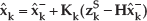
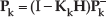
where
5. Performance evaluation
The performance of the presented stereo vision system for human tracking was tested within the working scenario of a mobile robot intended to follow a human co-worker in indoor applications, as well as in outdoor applications.
Experiments were conducted where a human walking in front of the mobile robot was imaged by a Point Grey Bumblebee XB3 [14] stereo camera mounted on the robot. The image pairs were grabbed at full resolution at 12fps (frames per second). Each pair of stereo frames was processed in order to extract information for stereo vision-based reconstruction of human walking with respect to a camera coordinate system. Some examples of processed images with superimposed extracted bounding boxes of humans are shown in Figure 5. The result of human detection in five frames from the video captured indoors is shown in Figure 5 (a)-(e). Figure 5 (f)-(j) shows the result of human detection in five frames from the video captured outdoors.

Human detection in sample frames of the videos captured indoor {a}-(e), outdoor (f)-(j)
In order to evaluate the performance of the system with respect to the accuracy of the reconstruction of the 3D coordinates of the person and therefore of the reconstruction of robot's distance to the person, the experimental results were compared with the ground truth obtained in two ways. In the first experiment the ground truth distance to the person was obtained by a Bosch PLR 50 digital laser rangefinder [15]. In the second experiment a reference path to be followed by the person was drawn on the floor. As the focus in this paper is the presentation of the vision module of the robotic follower, in the performed experiments the robot only observes the person without following him/her so that the errors possibly occurring in vision can be decoupled from possible errors introduced by the robot control.
In the first experiment, the distance computed from the output of the proposed stereo vision-based tracker according to:

was compared with the distance obtained by a Bosch PLR 50 digital laser rangefinder. According to the datasheet, the accuracy of this device is ±2mm regardless of distance. The system was tested on 1055 frames and the average error in distance was 2.38% at a standard deviation of 2.12 %.
Figure 6 shows the result of the second experiment where the reference path in the form of a 2.3times2.3m square is represented by the red line, while the output of the proposed stereo vision-based human detection without and with the tracking filter (Kalman estimation and prediction) are represented by the blue and green lines respectively.
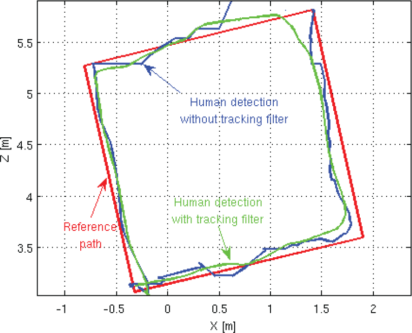
Comparison of the reference human's path and the human's paths reconstructed with the proposed stereo vision-based tracker with and without tracking filter
It can be observed that there is a region in the reconstructed path in the upper right corner where the proposed human detection gives no results. As is evident, the Kalman filter estimates and predicts the 3D position of the human in these frames, so that at any moment the proposed tracker outputs valid data. This is very important for proper robot control to avoid random movement of the robot. Also, the proposed tracker makes the reconstructed path smoother, which helps robot control to avoid erratic movements of the robot platform.
Besides providing reliable information for robot control, the Kalman prediction enables human detection to be performed on the image region of interest contributing to the cost effectiveness of human tracking. The processing time saved is between 30% and 70% of the time required to process the whole frame, depending on the size of the predicted region.
Besides the cost effective vision method, real-time robot control is supported by the proposed distributed computing. As mentioned before, the proposed system acquires image pairs from the on-board stereo camera at a rate of 12Hz. If image acquisition, the vision module and the robot control all ran on the on-board PC, due to the limited computational capabilities of the on-board, low-power PC, the vision module could only run at a rate of about 4Hz and could interfere with robot control by constantly blocking the CPU with image processing tasks. In order to avoid CPU blocking, the operations would need to run sequentially, as shown in Figure 7(a).

Timing diagram in case all operations run sequentially on one, low power computer (a), on different computers (b)
It can be observed that the total processing time of the system from image acquisition to sending speed values to the wheels is the sum of the three operations:

where T1, T2 and T3 represent the time periods required for each of the three operations to finish and they are 10ms, 250ms and 10ms respectively. Hence, if the operations would run sequentially, the output rate of the robot control would be limited to less than 4Hz, which could cause abrupt movements of the robot.
In order to overcome these problems, distributed computing was introduced in the presented system. This allowed the use of a separate high-end PC for running the vision module and a desktop PC for running the control module. In this way an individual module fully used all the available cores of the CPU without the necessity of leaving free resources to concurrent modules, as they run on separate machines. The introduction of such distributed computing results in a reduction in processing time for both the vision module (from 250ms to 75ms) and the robot control module (from 10ms to 4ms), as can be seen in Figure 7(b). Processing time for image acquisition remains the same (10ms) as according to system specifications given in Section 2 a low power on-board PC has to be used for acquiring the images
In the presented distributed computing system the three modules use the ROS library for communication, which implements socket communication over TCP (Transmission Control Protocol) in a way that is transparent to the user and therefore easy to use, debug and deploy.
Besides the introduction of distributed computing, real-time system characteristics are supported by pipelining as the use of distributed computing allows the operations to be performed in a pipeline fashion. That is, a module, which is upstream can already process new data while the downstream module processes its output. However, by using multiple computers additional transmission delays are introduced to the system, which are on average about 1ms for cabled connections (T23) and 5ms for wireless connections (T12 and T31). Figure 7(b) shows an overview of the timing when distributed computing is used. Black bars illustrate the times needed for processing image acquisition, vision and robot control, while the grey bars illustrate transmission delays. As the operations now run in parallel, the total processing time of a frame is given by the slowest operation, to which the communication times from and to that module are added.

where TTo and TFrom represent the transmission time required to send data from the previous module to the slowest module and from the slowest module to the next module in line. In Figure 7(b) the slowest module is the vision module, to which the transport times from image acquisition (T12) and to robot control (T23) are added. In pipelined systems there is another measurement, the system latency, which describes the time required for the final output to be delivered for a specific input. This is the sum of all operations, including all communication times.

In other words, after TL has passed and the pipeline is full, every other sample comes after a period T. Therefore, the pipelines are especially useful when all operations take approximately the same amount of time to be completed, since no module needs to waste PC resources by waiting for the next input.
It can be seen that while in the case of sequential processing, according to (23), the total processing time and implicitly the latency would be 270ms, reaching 3.7 Hz, after using distributed computing the processing time is 81ms leading to a potential rate of 12.34Hz and a latency of 100ms. Therefore, the 12Hz rate of the stereo camera can be maintained by all modules in the proposed system. Even though 12Hz is a good rate for obtaining reference values for robot control, in order to ensure smooth movement of the robot, in the proposed architecture the robot control additionally interpolates between two samples obtained from the vision module.
6. Conclusions
In this paper the vision module of a person-following robot is presented. It consists of two sub-modules: stereo vision-based human detection and human tracking based on a modified Kalman filter. The robustness of human detection is provided by combining disparity (depth) image-based features and reconstructed 3D human features. The Kalman filter-based prediction enables performing the human detection over the image region of interest rather than over the whole image, which makes the proposed human tracking method cost effective. The cost effective vision method is supported by distributed computing to support real-time performance of robot control. Experimental results on detection of humans in videos captured in both environments, indoor and outdoor, are given. The performance evaluation was carried out with respect to the accuracy of human tracking, as well as with respect to cost effectiveness of the presented vision module.
7. Acknowledgments
This research was partially supported by the DAAD-German Academic Exchange Service and the Ministry of Education and Science of the Republic of Serbia, through the bilateral project “A Novel Approach for Human Detection and Tracking in Robotics” within the PPP-Serbien programme.
This research was also partially supported by the European Commission as part of the CORBYS (Cognitive Control Framework for Robotic Systems) project under contract FP7 ICT-270219.