
Abstract
In this article, we present generic hierarchical behavior-based architecture model for driving mobile manipulator robots. Two behaviors are of high-level. They constitute the Supervisory agent, which manages the global system. Two others are of intermediate-level and finally one behavior is of low-level. These last ones constitute the Mobile Robot agent and the Manipulator Robot agent controlling, respectively, the mobile base and the manipulator arm. The choice of the suggested model is justified by the generic character of the proposed agent model and by the possibility of integrating the whole in a distributed robotic system. The model is formalized in Agent UML from the conceptual level to the implementation level. The interaction between the various agents is modeled by the use of the interaction diagrams of Agent UML (states and protocol diagrams).
Keywords
Introduction
The development of the robotic systems constitutes a very active field of research. During this last decade, we note the emergence of a new research discipline: The multi-agent systems. These latter ones are largely adopted in complex systems and distributed applications and, in particular, those dedicated to drive robotic systems as mobile robots, flexible cells, manipulator robots and mobile manipulator robots.
Multi-agent control is necessary when more than one robot is used to execute tasks, when a robot must coordinate the use of its own resources (coordinating the arm and the platform for a mobile manipulator robot) or when a robots society function independently on multiple tasks in a shared environment. The multi-agent systems are very suitable as regards the new software requirements thanks to their properties of decentralization, modularity, autonomy, effectiveness, reliability and reutilisability of agents for the implementation of other systems (Bonasso R. P., Firby R. J., Gat E., Kortenkamp D., Miller D., Slack M., 1997). Nevertheless, the development of this type of systems includes several problems. The absence of methodologies of design and implementation covering all the life cycle of the multi-agent system and allowing to understand, to represent, to analyze, to conceive and to implement such systems makes this task very difficult. We can also add other problems as the choice of agents' types, communication protocol, communication and interaction mode, conflicts management, environment modeling, tasks planning, scheduling, etc.
There is a large body of literature describing distributed architectures for driving robotics. In the following, we shall examine several of the better known robot architectures.
We can find a survey of existing systems composed of multiple autonomous mobile robots exhibiting cooperative behavior in (Cao Y. U., Fukunaga A. S., Kahng A. B., Meng F., 1995), (MacKenzie D. Ch., 1996) and (Cao Y. U., Fukunaga A. S., Kahng A. B., 1997). In addition, a state of the art in distributed mobile system is presented in (Parker L. E, 2000), and in particular, architectures that have been demonstrated in physical robot implementation. Balch in (Balch T., Arkin R. C., 1994) studied the importance of communication in robotic societies and described in (Balch T., Boone G., Collins T., Forbes H., MacKenzie D., Santamaria J.-C., 1997) the design and implementation of three eactive trash-collecting robots (Io, Ganymede and Callisto) including details of multi-agent cooperation, temporal sequencing of behaviors for task completion. Agah and al. in (Agah A., Bekey G.A., 1995) treated the problem of mobile robot colonies with populations of up to 100 robots. Robots in the colony perform tasks in dynamics world including different types of obstacles. They perform tasks including gathering of small objects, decomposing of large objects to smaller ones, and collecting of large, non-decomposable objects that require the cooperation of two robots. When a robot encounters such a task, it sends a call for help to the rest of the colony, and one or more other robots will respond.
Innocenti and al. (Innocenti B., Lopez B., Salvi J., 2003) developed a multi-agent architecture comprising the following agents: Task Planning agent which provides tasks plan, Reactive agent for obstacles avoidance, Monitor agent controls the system and detects execution problems, Facilitator agent which have knowledge of the various agents of the system and the User Interface agent that allows to introduce problems and display results progressively.
Toukal in (Toukal Z., 2000) proposed an approach for multi-robots organization driving. The organization is subjected to functioning constraints as dynamic environment and coupling of robots operations plans. Each robot of the organization is assimilated to a hybrid agent on several levels. His architecture contains two various agents' types: Global Planning agent which provides operations plans and transmits them to the other Robots agents; and Robot agent which has an objective and a plan associated to it, and a local scheduler.
For soccer robots, and as said in (Balch T., 1999), is a rich task for multi-agent research because it requires cooperation between teammates, competition versus an opponent and unpredictable dynamic play. Kitano and al. (Kitano M., Asada M., Kuniyoushi Y., Noda I., Osawa E., 1997) promote the Robot World Cup (RoboCup) as a vehicle for multi-agent research (intelligent control, inter-agents communication, images processing, artificial life, etc.). The RoboCup league focused first on basic skills to control ball (Asada M., 1997) as ball moving, ball catching (single agent skills), and passing the ball between two players (cooperative behavior) and moved towards tactics to escape from off-side traps which require recognition of intention of opponent players/teams. Also, opponent modeling and and management of team strategies would become more important (Asada M., Suzuki S., Veleso M., Kraetzschmar G. K., Kitano H., 1999).
A driving architecture was developed in (Ouelhadj D., Hanachi C., Bouzouia B., 1998), (Ouelhadj D., Hanachi C., Bouzouia B., 1999) and (Bouzouia B., Bouchemma R., 2004) for flexible manufacturing cells. This architecture, based on a multi-agent system, used the Contract Net protocol (Davis R. & Smith R. G., 1983) to reschedule operations in case of a dysfunction. The proposed approach models the cell by a cognitive agents' society and assigned each resource to a Resource Driver agent. The Task Manager agent is the supervisory of the cell.
Leitão and al. (Leitão P., Restivo F., Putnik G., 2001) also proposed the ADACOR architecture (Adaptive and Cooperative Control Architecture for Distributed Manufacturing Systems) to control flexible manufacturing cells. ADACOR defines a set of agent classes: Operational agent which interacts with the physical resource, Supervisor agent that manages the Operational agents, Product agent represents available product in the system, Task agent executes machining tasks and finally System Management agent that administrates the system.
Fraile and al. (Fraile J.-C., Paredis C.J., Wang C.-H., Khosla P. K., 1999) proposed a planning and control architecture to assembly parts for manipulator robots. This work is mainly divided into two phases. An off-line phase produces the preliminary decomposition of the assembly tasks. This phase produces an assembly plan. The second phase is on-line and concentrates on the attribution and execution of tasks. This architecture comprises the following agents: Scheduler agent schedules the assembly operations and assigns them to the available resources, Manipulator agents control manipulator robots, Trajectory planning agent generates free-collision movements, Communication agent that handles messages and Graphic Simulator agent for visual verification of the execution of tasks.
Laengle and al. proposed in (Laengle Th., Lueth T.C., 1994), (Lueth T. C., Laengle Th., 1994) and (Laengle Th, Lueth T.C., Rembold U., Woern H., 1997) the distributed control architecture KAMARA (KAMRO's Multi-Agent Robot Architecture) to drive the KAMRO (Karlsruhe Autonomous Mobile Robot) mobile manipulator robots. In this architecture, a robot meta-agent is composed of three parts: The Communicator agent is a communication channel connecting the Head agent to the other agents of the same level or higher, the Head agent selects plans and actions for tasks execution, and the Body agent which is composed itself by several other agents.
Shell in (Shell D. A., Mataric M. J., 2005) described a united action-centric methodology for generating a wide range of humanoid robots behavior from natural motor control for humanoids to effective collective behavior for robot teams.
The ALLIANCE architecture is developed by Parker (Parker L. E., 1998) in order to study cooperation in heterogeneous robot teams where not all tasks can be performed by all team members. ALLIANCE is a fully distributed, behavior-based architecture which gives all robots the capability to determine their own actions. It defines a mechanism that allows teams of robots, each of which possesses a variety of high-level functions that it can perform during a mission, to individually select appropriate actions throughout the mission based on the requirements of the mission, the activities of other robots, the current environmental conditions, and the robot's own internal states. Under the behavior-based framework, the task achieving behaviors of each robot receive sensory input and control some aspect of the actuator output. Lower-level behaviors, or competences, correspond to primitive survival behaviors such as obstacle avoidance, while the higher-level behaviors correspond to higher goals such as map building and exploring. The output of the lower-level behaviors can be suppressed or inhibited by the upper layers when necessary.
The analysis of works exposed previously enabled us to choose a multi-agent system based on hybrid (reactive and deliberative) agents. This allows obtaining reactive behaviors on several levels adapted to all the possible situations.
This paper presents a multi-agent architecture for driving mobile manipulator robots. The final aim of this work is being the integration of the RobuTER mobile manipulator robot (Guérineau N., Moignard C., Pomiers P.) (http://www.robosoft.fr/) within a flexible manufacturing cell or a complex robotic system which comprises several heterogeneous resources (manipulator robots, mobile manipulator robots, conveyors, CNC, etc.).
The paper is organized as follows. The next section gives the agents decomposition of the proposed architecture. The third section describes the various components of the Agent UML (Agent Unified Modeling Language) methodology and the application of its diagrams on our driving architecture. The fourth section presents the behavioral aspect of the driving architecture which is based on the concept of hierarchical behaviors. The architecture of the RobuTER mobile manipulator robot is presented in the fifth section. An example of the system as a whole and of its agents' functions while performing a mission is presented in the sixth section. Finally, a conclusion is presented together with an outline on future works in the seventh section.
Agents' decomposition of the architecture model
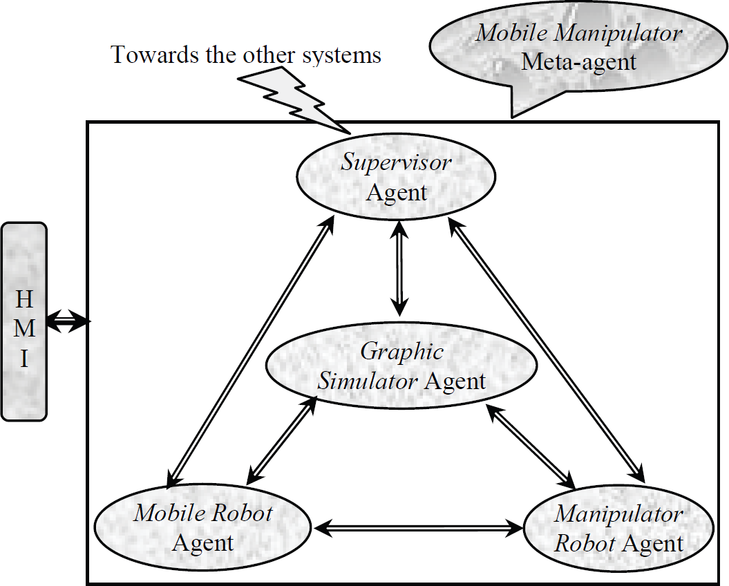
We chose to model the mobile manipulator robot by a Mobile Manipulator meta-agent constituted of three hybrid agents driving the whole of the robot resources (see Fig. 1) (Hentout A., Bouzouia B., Toukal Z., 2005) (Hentout A., Bouzouia B., Toukal Z., 2008b). Each agent models a principal function of the robot and manages a different subsystem. The first two agents, Mobile Robot agent and Manipulator Robot agent, drive, respectively, the mobile base and the manipulator arm. The third agent, Supervisory agent, is dedicated to the management of the whole of the system. A fourth agent, Graphic Simulator agent, plays the role of a real time graphical verification of operations and mission execution.
The proposed driving architecture model
Considering the nature of the robot to be driven, which consists of two heterogeneous resources (mobile base and manipulator arm) which must synchronize themselves, cooperate and coordinate for common tasks, a total distribution of knowledge and control is required. This distribution is ensured by messages exchanged between agents.
Assigning an agent for each function and subsystem allows increasing the treatment performances and, in particular, in term of computing power that plays a significant role at the occurrence of a disturbance.
The knowledge base of the Supervisory (Mobile Robot/Manipulator Robot) agent describes the hardware configuration of the robot (resource) and contains the whole of the scheduled jobs (operations) of a mission (job) to execute. It describes also the engagements of the agent for the launching of jobs (operations) to carry out. In what follows, we shall briefly explain the roles and the internal structures of the various agents. For more details, see (Hentout A., Bouzouia B., Toukal Z., 2005), (Hentout A., Bouzouia B., Toukal Z., 2007) and (Hentout A., Bouzouia B., Toukal Z., 2008b).
The role of the Supervisory agent is to interpret the received mission and to put it in the form of a jobs plan. Each job is distributed on the two other agents in the form of an operations plan. This agent is constituted by the following competences:
Module of configuration: Definition of the acquaintances, the list of missions that the robot can execute and the description of its environment. Module of missions' management: This module decides on the acceptance or the refusal of the received mission. It then checks the availability and the state of all the resources of the robot. If the mission is accepted, it sends it to the module of jobs management and execution control. Otherwise, it informs the transmitter of its incapacity to achieve it. Module of low-level communication: The function of this module is, on one hand, the capture, the interpretation and the treatment of messages and events sent by the other agents of the meta-agent, and on the other hand, the coding and the transmission of messages and events to send. Module of high-level communication: Ensures the information exchange with the outside of the meta-agent. Module of jobs management and execution control: If the mission is accepted, this module interprets it into scheduled jobs plan, distributes them on the concerned agents and manages their execution. The scheduling of the various jobs realized, either locally, or in a coordinated manner with the other meta-agents of the system.
Mobile Robot agent / Manipulator Robot agent
The first agent (Mobile Robot) ensures the local management of the mobile base, the second (Manipulator Robot) that of the manipulator arm of the robot. Their architectures confer to the robot, at the same time, reactive and deliberative capacities reasoning on complex situations. Each agent must constantly know its execution state which is related to its environment context (disturbances, presence of obstacles, etc.), and adapt itself to this environment by elaborating another plan.
To this end, each agent has the following competences:
Module of configuration: Allows to add and to remove tools and equipments and to define the list of operations which a tool or equipment can carry out. Module of communication: Ensures the communication with the other agent of the meta-agent. Module of sensors management: Takes care, on one hand, of the collection of all information from the various sensors equipping the robot and, on the other hand, of the pre-treatment of this information in order to extract useful information from them. Module of trajectories generation and navigation/movement: It establishes trajectories while taking into account its environment by the implementation of obstacles avoidance strategies, target tracking, etc. Module of monitoring: Carried out in parallel with the preceding module to transmit to the module of operations management and execution control the execution state of the operation in progress. When a dysfunction incident occurs, it carries out a diagnosis enabling it to locate the source of the anomaly by launching the inference on the fact base. Module of operations management and execution control: Elaborates an operations plan in collaboration with the other agent and launches the various operations appearing in its calendar.
After having presented the decomposition into agents of the driving architecture, we shall describe the various components of the Agent UML methodology and the application of its various diagrams on our architecture in the next section.
Modeling the driving architecture
Recently, much of efforts were deployed to fill the gap between the agent technology and methodologies of design and implementation of agent-based systems. These efforts led to many methodologies. We find in (Iglesias C. A., Garijo M., Gonzalez J. C., 1998), (Sabas A., 2001) and (Hentout A., Bouzouia B., Toukal Z., 2008) a variety of examined approaches. They constitute either an extension of traditional methodologies (object-oriented) or an extension of knowledge-based methodologies and some ones are conceived for a particular context (Sabas A., 2001).
The Gaia methodology (Wooldridge M., Jennings N. R., Kinny D., 2000) covers two phases of software development: The analysis phase produces the roles model and the interaction model; the design phase is based on agent model, services model and acquaintance model. The Tropos methodology (Giunchiglia F., Mylopoulos J., Perini A., 2001) is based on the concepts of agent, goal and plan and a crucial role is assigned to the requirements analysis and specification. The Multiagent Systems Engineering (MaSE) methodology (DeLoach, S. A., Wood, M. F., Sparkman, C. H., 2001) is composed of two phases: The analysis phase proceeds in three steps: capturing goals, applying use cases and refining roles; the design phase comprises four steps: creating agent classes, constructing conversations, assembling agent classes and system design. Aalaadin (Ferber J, Gutknecht O., 1998) is based on the concepts of agent, group and role and proposes a three phases process (Augeraud M., Collé F., Sarramia D., Boussier J.-M., 2006): The analysis phase is used to identify the functions of the system; the design phase allows to identify groups and roles through organizational structures diagrams as well as the description of the interactions between roles by sequence diagrams; the last phase begins with a choice of agent architecture and instantiates the organizational structures in concrete organizations. The Prometheus methodology (Padgham L., Winikoff M., 2002) consists of three phases: The system specification phase to identify the basic functionalities of the system: the input, the output and any shared data source; the architecture design phase uses the output to determine which agents the system will contain and how they will interact; and the detailed design phase focuses on developing the internal structure of the agents. The most notable work in this field is the Agent Unified Modeling Language (Agent UML) (Bauer B., Muller J. P., Odell J., 2001) (Bauer B., 2001) (http://www.auml.org). In this language, the Unified Modeling Language (UML) (Booch G., Rambaugh J., Jacobson I., 1999) is intensively employed to model all the aspects of the agents. Since Agent UML is an extension of UML in order to take into account the properties of agent, Agent UML inherits the representations proposed by UML. The UML sequence diagrams were modified into protocol diagrams in (Bauer B., Muller J. P., Odell J., 2002) and correspond to the representation of the interaction protocols. The class diagrams were also modified in (Bauer B., 2001) and (Huget M.-P, 2002a).
In the rest of this section, we shall present our experiment on the application of Agent UML to our driving architecture. We shall present the three types of diagrams that we use and exploit in this work (agent diagram, states diagrams and protocol diagrams).
The choice of Agent UML is justified by (Bauer B., Muller J. P., Odell J., 2001) (Bauer B., Muller J. P., Odell J., 2001b) (Bergamaschi S., Gelati G., Guerra F., Vincini M., 2003):
To employ agent-based programming, a specification technique must support the whole software engineering process from the identification of the requirements of the system, through analysis and design, and finally to system implementation. The UML language is gaining wide acceptance for the representation of object-oriented software. Agent UML leverages the expressive power of this existing language by extending it. Agent UML leverages on existing knowledge, proposing to designers and developers to learn extensions of something they already know. Agent UML allows representing the internal behavior of an agent.
Agents diagram
The first level of the Agent UML modeling defines the classes of the agents present in the system. Agent UML allows representing several abstraction levels when designing agent diagram. We are interested in the two following levels:
The conceptual level: it is the high view of the multi-agent system by eliminating all unnecessary information to understand the structure of the system. The implementation level: gives a detailed view of the contents of the agents, classes and various relations.
Fig. 2 shows the agents diagram of conceptual level detailing the various agents of our system (Hentout A., Bouzouia B., Toukal Z., 2008).
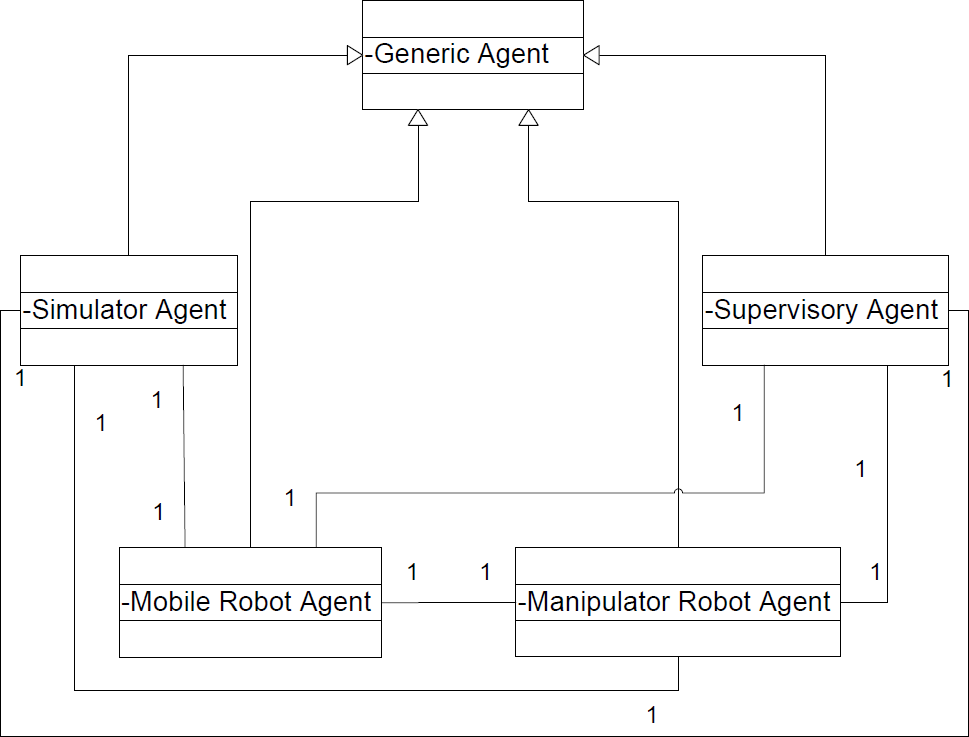
Agents diagram (Conceptual level)
For the definition of the agent diagram (implementation level) of the Supervisory agent (see Fig. 3) (Hentout A., Bouzouia B., Toukal Z., 2008), we followed the modifications made in (Bauer B., 2001).

Agent diagram of the Supervisory agent (Implementation level)
In this case, the agents diagram consists of several fields. The first one is associated to the name of the agent: Supervisory. The following field called State gives all the attributes of the agent. In this example, we find those related to the agent identity, IP address, etc. The third field is the Actions field. We distinguish two types of actions: proactive actions (≪Proactive≫) and reactive actions (≪Reactive≫). Many proactive actions are defined here: CloseNegotiation, ExtendNegotiation, AcceptProposition, RefuseProposition, etc. We also defined a reactive action: Propose. The next field is Methods. They are defined as in UML, with, eventually, pre- and post-conditions. We give here four methods for our example: SendCallForTender, SendProposition, SendContract, SendAcceptance, SendRefuse, etc. The last field gives the Supported protocols. Here, we mentioned the Call for Tender communicative act to call for tender. We also give the Default act which is used to react to all kinds of received acts. The communicative act Not-understood is sent each time when an entering act cannot be interpreted.
Many interactions exist within our architecture model involving many diagrams. We shall give the states diagrams and a protocol diagram of the Supervisory agent. For more details, see (Hentout A., Bouzouia B., Toukal Z., 2008).
The States diagrams are used to represent the dynamic behaviors of the system agents. These diagrams are interested in the various states of the system and which actions occur in the environment, the events or the received messages which allow passing from one state to another. The initial state of the diagram is the Idle state (Huget M-P, 2002b).
We present here the states diagram of the Supervisory agent (Hentout A., Bouzouia B., Toukal Z., 2008). From the Idle state and at the reception of a call for tender on a mission to execute, the Supervisory agent decides on the refusal or the acceptance of this mission. In the first case, the agent sends the refusal causes. In the other case, the agent begins a negotiation with the high-level in order to arrive, by sending propositions and receiving refusals or acceptance, to an agreement on the execution of this mission. If a proposition is accepted, this agent starts generating jobs plans and distributes them on the concerned agents. Finally, it starts the execution of the mission. If an error occurs during an operation, the Supervisory agent establishes an error report and sends it to the high-level.
Fig. 4 presents the states diagram of the Supervisory agent.
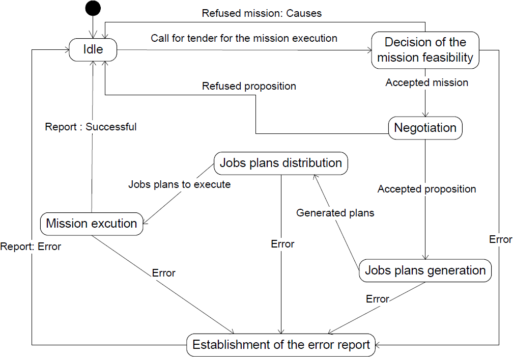
States diagram of the Supervisory agent
The protocol diagrams describe the interaction protocols used by the agents. These diagrams represent the messages exchanged between agents. They show the agents participating in an interaction and the events they generate, organized in a sequence in time.
We are interested here by the protocol diagram corresponding to the decision of feasibility of the received mission (Hentout A., Bouzouia B., Toukal Z., 2008). This diagram utilizes all the agents of the multi-agent system. Indeed, when the high-level sends a call for tender on a mission to execute, it is received by the Supervisory agent which decides on the feasibility of the mission and sends, according to the case, a proposal (if acceptance) or refusal causes (if refusal). If the high-level does not accept the proposal, it sends the refusal causes. Otherwise, the high-level sends a contract message to the Supervisory agent. This latter one interprets the mission into two plans (P1 and P2) and distributes them on the two other agents (Mobile Robot and Manipulator Robot).
Fig. 5 shows the protocol diagram of the decision of feasibility of the received mission of the Supervisory agent. After having presented the Agent UML diagrams of the proposed architecture model, we shall present its hierarchical and behavioral aspects in the next section.

Protocol diagram of the decision of feasibility of the received mission of the Supervisory agent
The driving architecture presented in Fig. 1 is based on the concepts of behaviors, competition and hierarchy (hierarchical behaviors). Each level of behavior is competitor with capacities of environment perception, decision, communication and action on the environment (see Fig. 6) (Hentout A., Bouzouia B., Toukal Z., 2007) (Hentout A., Bouzouia B., Toukal Z., 2007b). The implementation of a behavioral agent results from the activation of one or several competences (Toukal Z., 2000).

The behavior-based driving architecture model
The Supervisory agent is composed of one piloting layer only (Hentout A., Bouzouia B., Toukal Z., 2007) (Hentout A., Bouzouia B., Toukal Z., 2007b), which is independent from the nature of the robot. Its role is to send instructions to the other two agents and to receive reports on the execution of the transmitted operations plans.
The two other agents are composed of two layers (Hentout A., Bouzouia B., Toukal Z., 2007) (Hentout A., Bouzouia B., Toukal Z., 2007b):
Piloting layer: it is also independent from the nature of the robot. It receives an operations plan from the Supervisory agent, and sends each one of these operations to the operative layer for execution. Operative layer: it is adapted to the architecture of the robot. This layer transmits instructions to be executed by the various actuators, and receives information generated by the robot sensors. After execution of each operation, this layer sends a report to the piloting layer.
To each layer corresponds a mechanism connecting the three capacities: Perception, Decision and Action developed below. From this point of view, various abstraction levels are introduced in the Action. This allows a behavioral agent of level n to express its Action in term of behaviors of level n-1. Also, the Supervision module is a virtual entity whose role is to select modules which result in the necessary behavior facing a given situation.
Finally, the proposed behavior-based architecture is a set of three successive software layers built around the virtual robot layer (this layer allows to consider sensors and actuators as accessible entities by means of sub-routines). The operative layer is directly connected to the virtual robot layer. In its turn, this layer itself is built on the material capacities of the physical robot (material resources of the robot).
The high-level of the architecture defines the Supervisory agent having two behaviors: high-level singular and cooperative behaviors. The intermediate-level and the low-level define the Mobile Robot and Manipulator Robot agents. Both of which have three behaviors: two intermediate-level singular and cooperative behaviors, and one low-level behavior.
We distinguish two types of behaviors: (Hentout A., Bouzouia B., Toukal Z., 2007) (Hentout A., Bouzouia B., Toukal Z., 2007b)
High-level singular behavior
this level manages the individual strategy of the agent with respect to its mission. Three examples of this type of behaviors are given here below:
During an operation of hardware configuration, the Supervision module activates modules of configuration and of low-level communication. The procedure of establishment of an initial jobs plan requires the activation of the missions' management and the high-level communication modules. Following the occurrence of a disturbance, the robot adopts a deliberative behavior based on its environment knowledge and on a representation of its state. This knowledge is used to carry out a new scheduling of its plan in order to satisfy its own objectives. To this end, the Supervision module incorporates the two following modules (fig. 7): Jobs management and execution control and Low-level communication.

High-level singular behavior
This behavior uses the three capacities established above:
Perception: to apprehend the internal state of the disturbed agent (nature of disturbance, generated delay, time passed since the starting of the plan, job and operation in progress, exception state towards which the agent is pushed, etc.). Decision: it is based on the internal state of the agent and a priori knowledge available in its knowledge base. This allows to establish a new plan and to evaluate, thereafter, its impact on the agent itself (delays induced by the disturbance on its operations). Action: if the obtained plan satisfies all the constraints, it is validated and placed in the bill book of the agent. Thereafter, an intermediate behavior is activated which means the resumption of the normal situation. Otherwise, it activates the cooperative behavior of the same level.
it manages the collective strategy of the agent; i.e., the management of its plan in collaboration with the other meta-agents of the system. For example, several meta-agents participate in the establishment of the jobs plans intended for each one in order to achieve the total mission. In this case, each meta-agent adopts a deliberative behavior based on local knowledge and on exchanged information.
This behavioral agent incorporates the module of Jobs management and execution control, High-level communication and Low-level communication (fig. 8).

High-level cooperative behavior
The three capacities are:
Perception: to perceive the internal state of the agent due to local knowledge and to exploit the information exchanged between the meta-agents of the system. This constitutes the resulting knowledge source. Decision: it is ensured by the module of jobs management and execution control and the module of high-level communication. These modules proceed by negotiation between meta-agents, and using the resulting knowledge source in order to elaborate, for each meta-agent, its jobs plan. These plans must satisfy all the constraints imposed on the mission. Action: each job of the plan is distributed in the form of operations plan on the agents constituting the meta-agent (Mobile Robot and Manipulator Robot agent). This procedure activates the intermediate level.
The second level of intelligence carries out the operations plan provided by the high-level. The behavioral agent of this level is only responsible for the release of a low-level behavior to treat the events.
In a similar way, we distinguish two types of behaviors (Hentout A., Bouzouia B., Toukal Z., 2007) (Hentout A., Bouzouia B., Toukal Z., 2007b):
Intermediate-level singular behavior
it is necessary for the execution of the operations plan of the agent. It proceeds to launch operations, to check pre-and post-control conditions and to receive and to analyze reports resulting from the low-level. This analysis allows deciding on the execution state of the operation in progress (failure, success, etc.).
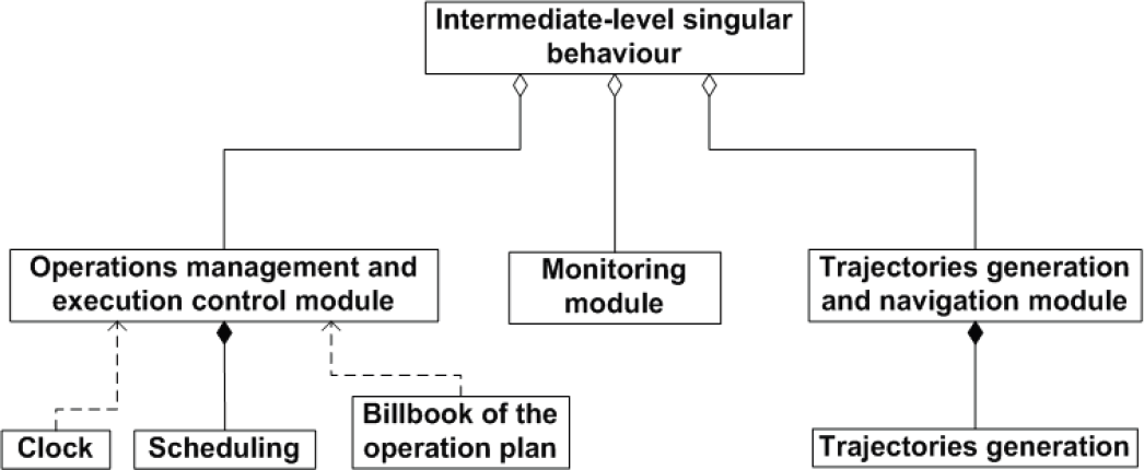
An example of this type of behavior is the one activated during a sub-plan research process. This sub-plan is inserted in the initial plan while satisfying the temporal constraints. The sub-plan may correspond to a set of complex obstacle avoidance trajectories strategy. This process is carried out locally by implementing the following modules (fig. 9): Operations management and execution control, Monitoring and Trajectories generation and navigation/movement.
Intermediate-level singular behavior
In this case:
Perception: it returns the execution state of the operation in progress. It is based on the events incoming from the clock, which indicate the occurrence of envisaged events (beginning or end of an operation); and on the messages incoming from the low-level which correspond, either to the envisaged moments in the bill book of the operations plan (normal execution of an operation), or to unforeseen moments (occurrence of a disturbance). Decision: taking into account the current execution state, the agent must make a decision with respect to the low-level. For example, with the occurrence of an event, it checks if this date is compatible with the bill book of the operations plan. In case of compatibility, it gives order to execute the next operation. Otherwise (disturbance occurrence), it carries out the establishment of a recovery procedure while trying to guarantee the imposed temporal constraints. Action: consists of the activation or the deactivation of a third-level behavior. It is a purely reactive behavior (simple obstacles avoidance) or a hybrid one (piece recovery). In addition, the action can be expressed by the activation of the cooperative behavior of the same level.
it is ensured by the implementation of a coordination process between the agents of the same meta-agent without competition of the Supervisory agent.
An example of cooperative behaviors consists in implementing a cooperation procedure between the mobile base and the manipulator arm in a fall event of a part initially seized by this latter. In this case, the two intermediate agents exhibit, each one, a behavior which aims to recover the above-mentioned part.
This behavior is obtained by associating the following modules (fig. 10): Operations management and execution control, Monitoring, Trajectories generation and navigation/movement and Communication.

Intermediate-level cooperative behavior
This behavior uses the three following capacities:
Perception: in addition to the information perceived in the preceding case, other information relating to the execution state of the other agent is taken into account in order to have a more complete environment state. Decision: obtained by the participation of the module of operations management and execution control and module of communication. An inter-agents negotiation process of the same meta-agent, which rests on the environment state described as complete, is launched to establish, for each one, a satisfying operations plan. Action: in a similar way, this capacity allows validating the plan thus established then to activate or deactivate a low-level behavior. In case of failure of the establishment procedure of the operations plans, the Action is summarized to request the high-level.
The low-level behaviors allow, in general, the management of the instructions to send to the various actuators of the system according to sensors information. As the environment in which the robot system evolves is dynamic, several behaviors of this type may impose themselves. The most frequent example is that of a reactive behavior allowing simple obstacle avoidance or target tracking. The whole of these behaviors rests on an on-line control of the trajectory initially generated (Hentout A., Bouzouia B., Toukal Z., 2007) (Hentout A., Bouzouia B., Toukal Z., 2007b).
To this behavioral agent, we associate the following modules (fig. 11): Operations management and execution control, Trajectories generation and navigation/movement and Sensors management.

Low-level behavior
In this case, the capacities are expressed as follows:
Perception: The robot is equipped with sensors enabling it to locate itself in its environment and to know its obstacles proximity. A sensors data processing is necessary, allowing the determination of the robot position in its environment (workspace and obstacles). Decision: faced to a situation, this capacity allows the selection of a suitable low-level behavior. It is a purely reactive behavior type of obstacles avoidance, moving towards a point or tracking a target, etc. To implement these behaviors, we can exploit techniques based on fuzzy logic, neurons networks, genetic algorithms and others. Action: consists in activation or deactivation of the behavior chosen by the Decision activity, by generating instructions of speed or position control according to functionalities used by the virtual robot. For each point of the trajectory, the corresponding instructions are sent to the virtual robot layer, which, in its turn, transmits them to the various actuators.
In the previous sections we have exposed the various components of our driving architecture. We presented the decomposition into agents of the proposed architecture and the different competences and the role of each agent. Also, we presented the necessary behaviors facing a given situation. In the next section, we shall present an example of a mission to be executed by a mobile manipulator robot. We shall give the agents' functions, the different behaviors activated depending on the situations encountered by the robot and, finally, the different messages exchanged (protocol diagram).
The mission to carry out is introduced by an operator or received from the high-level. It consists in moving towards a desired position in order to seize an object.
Before beginning the execution of this mission, the Supervisory agent starts a negotiation with the high-level in order to arrive to a compromise on the execution of the mission (high-level singular behavior). In case of success, the Supervisory agent interprets it into two plans and distributes them on the two other agents (Mobile Robot and Manipulator Robot).
The mission to be carried out consists in two tasks plans. The first plan, executed by the mobile base, moves the robot towards the final position while avoiding unforeseen obstacles. This plan is composed of the following tasks:
Generation of the trajectory to move the robot towards the desired position: an intermediate-level singular behavior is activated here. If an obstacle is detected during the execution of the generated trajectory, the Mobile Robot agent informs the Supervisory agent. This latter one will generate a recovery plan to avoid this obstacle: it corresponds to a low-level behavior. At the end, a report is sent to the Supervisory agent (base in position).
The second plan, executed by the manipulator arm, has as an objective the seizure of the object. It is composed of the following tasks:
Generation of the movement to seize the object: an intermediate-level singular behavior is activated here. If the object is missed during the execution of the movement, the Mobile Manipulator agent informs the Supervisory agent. This latter will generate a recovery plan to seize the object. The plan is generated either locally or in a coordination manner. In the first case, the plan involves the Manipulator Robot agent only and an intermediate-level singular behavior is activated. In the last case, an intermediate-level cooperative behavior is activated and both the Mobile Robot and the Manipulator Robot agents are involved. At the end, a report is sent to the Supervisory agent (object seized).
The different messages exchanged between the agents and the events they generate are presented in Fig. 12.

Protocol diagram of the mission to be executed
Let's remember that the aim of these works is the development of distributed architecture for driving mobile manipulator robots. The robots will be integrated within a flexible manufacturing cell or a complexes robotic system where there will be several heterogeneous resources.
To be able to implement the suggested driving architecture, the operative layer must be adapted to the architecture of the robot to be driven. In the next section, we shall describe the material and the software architecture of the experimental robot (RobuTER). This will enable us to see the possibility of implementing our solution on such architecture.
RobuTER/ULM architecture
The mobile manipulator robot RobuTER/ULM is a set of a platform surmounted by a six d.o.f manipulator arm with a grip. The platform and the arm are controlled by an embedded industrial PC and by four MPC555 microcontrollers' cards communicating via a CAN (Controller Area Network) bus. The first MPC555 controls the mobile base. Two others control the first three and the last three links of the arm. The last MPC555 controls the six axes force sensor of the manipulator arm.
The architecture described above can be schematized in the following way (see Fig. 13) (Hentout A., Bouzouia B., Toukal Z., 2007) (Hentout A., Bouzouia B., Toukal Z., 2008b):

RobuTER/ULM architecture
In the case of RobuTER, the virtual robot layer is composed of two parts. A first part developed under SynDEx (Synchronized Distributed Executive) (http://www.syndex.org/) and carried out in microcontrollers' cards (actuators control, odometric sensors reading, etc.). A second part developed in C/C++ and carried out in the embedded PC (ultrasonic sensors, LMS sensor, etc.).
The interaction between the low-level of the architecture (the operative layer) and SynDEx is done via shared memories Linux_IO. These memories are parts of Linux/RTAI kernel and considered as an interface between C/C++ application and the one developed under SynDEx. The development of the application is structured into two parts with a data exchange using the Linux/RTAI layer. This data exchange between the two parts allows sending instructions, reading sensors measurements or receiving reports on the execution of these instructions.
A high-level part: written in C/C++ and being carried out in the embedded PC (navigation strategies, trajectories planning, etc.). A low-level part: under SynDEx and being carried out in the microcontrollers cards (sending of instructions to actuators, sensors reading, etc).
The shared memory comprises several types of data:
Boolean: success or failure of execution of the sent instructions; Reading only sensors information: periodically refreshed by Linux/RTAI layer (odometry, force sensor, etc.); Writing only actuators information: also periodically refreshed by Linux/RTAI layer (arm and base actuators, etc.).
These two application parts constitute an embedded real time application. The data exchange between the two parts allows sending instructions, reading sensors or receiving reports on the execution of these instructions.
Conclusion
In this paper, we have presented an architecture model for driving mobile manipulator robots under development. The model uses hybrid agents which allow obtaining behaviors adapted to the various situations and reactivities at several levels. This model privileges control and knowledge distribution and coordinated management of the unforeseen situations. The choice of multi-agent model is justified, on the one hand, by the generic character of the proposed agent model (independently of the robot nature) and, on the other hand, by the possibility of integrating the whole in a distributed robotic system.
We also formalized this architecture model by Agent UML from the high-level (conceptual level) to the low-level (implementation level). The choice of Agent UML was a considerable help to us. Indeed, its concepts related to agent technology allow expressing them in a very advanced graphic notation with a well defined semantics. Also, and following the Agent UML notation, we were obliged to reason in terms of agents and their properties instead of reasoning into object.
The model is a three-level hierarchical behavior-based architecture. The high-level behaviors manage those of the intermediate-level, which, in their turn, manage those of low-level. To each level corresponds a mechanism connecting the three capacities: Perception, Decision and Action. These levels of abstraction are hierarchically proportional to their functional and cognitive richness. This work opens future prospects in short, medium and long terms. In short-term, we project to implement a simulator to validate the functional aspect and the various behaviors of the proposed architecture. In medium-term, validation of the proposed architecture in a real site (RobuTER). In long-term, we shall work on the integration of RobuTER within a distributed robotic system (manufacturing cell).