
Abstract
For any multi-DOF parallel mechanism, its system model is difficult to accurately establish and high-performance control is hard to achieve because of its high nonlinearity and strong coupling characteristics. In view of this, for a 6-PTRT parallel mechanism, the coupling characteristics are first analysed and then a novel smooth sliding mode control algorithm based on synchronization error is designed and the system's stability is proven - in theory - according to the Lyapunov stability theorem. By introducing the defined synchronization error into the smooth sliding mode control, the proposed method can resist the coupling effect among the branches of the parallel mechanism and realize the coordinated, synchronous and more accurate movement of each branch of the parallel mechanism with no accurate system model, whereby the tracking error of each branch may converge on zero simultaneously. The simulation results show that the synchronous smooth sliding mode control method proposed here has a shorter response time and a higher control precision when compared with the smooth sliding mode control method. By considering the errors of the adjacent branches, the synchronous coordination among the branches of the parallel mechanism with the coupling effect is effectively improved.
Keywords
1. Introduction
A parallel mechanism with the advantages of high rigidity, strong structure vibration resistance, heavy payload, small moving inertia, a fast response speed and so on [1], [2], [3], [4], when compared with a serial mechanism, can allow for parallel robots in various applications, such as machine tools [5], manufacturing lines [6], climbing robots [7], aperture spherical radio telescopes [8], haptic devices [9] and so on. It has been a popular research focus in the field of robots.
The aforementioned advantages are accompanied by several challenges for the control of a multi-DOF parallel mechanism. Due to the fact that the pose of the end effecter of the multi-DOF parallel mechanism is difficult to detect rapidly and directly in real time, it is hard to realize the full closed-loop pose control of the parallel mechanism [10]; typically it is treated as a multiple single-branch system. Some control methods have been presented, such as proportional-integral-derivative control [11], adaptive control [12], fuzzy logic control [13], neural network control [14], and so on; these include some control schemes combined with several control methods, but these controllers are directly derived from the control methods of the series mechanism. Essentially, the characteristics of a parallel mechanism with a plurality of branches are not taken into account; consequently, the coordinated motions among the branches are ignored [15]. Since the motion trajectory of the end-effector is determined by all of the branches' motions, all of the branches of the parallel mechanism should be controlled in a synchronous manner so that a predetermined trajectory can be followed with high tracking accuracy [16].
The coupling among the branches of the parallel mechanism is the main factor which affects the control precision and the coordinate synchronization of each branch, and it takes the difficulties to the high-performance control for the parallel mechanism. To solve the coupling and synchronized control problems of parallel mechanisms and their equipment, some explicit-dynamic-model-based control design methods have been proposed. Koren [17] initially proposed the synchronized control concept and applied it to the tracking control of machine tools; for a parallel robot, a decoupling controller for adopting cross-coupling pre-compensation is proposed to weaken the system dynamic coupling effect in [18]; a synchronization controller based on contour errors for a parallel robot is designed to improve the position precision of the trajectory tracking control and improve the coordination among the joints of the parallel robot system in [15]; for a 4-SPS type parallel manipulator, a synchronized control algorithm for synchronizing all of the actuators' tracking by selecting a tracking error as a standardized tracking error is proposed in [19]; an adaptive synchronized control is proposed in [20] for improving the tracking accuracy of a PRR type planar parallel manipulator; a control approach based on adaptive control with the use of defined synchronization error is proposed in [21] to improve the motion coordination of a plane parallel robot, but it is very difficult for a multi-DOF parallel mechanism to obtain the synchronous error as defined in the literature. These explicit-dynamic-model-based control design methods may improve the synchronized control performance of a parallel mechanism, but due to the complexity of the dynamic model of a multi-DOF parallel mechanism, it takes a long time to solve the inverse dynamics, and it is difficult for the control system to meet real-time requirements [22], [23]. For a 6-DOF hydraulic parallel manipulator, a strategy based on a kinematic model is proposed in [24], where the cascade control and the crossing-coupling control methodology are integrated to achieve synchronous tracking control; for parallel manipulators, a synchronized control algorithm for incorporating cross-coupling technology into a PD control architecture is presented to synchronize all of the actuators' motions in [25]; a nonlinear PD synchronized control for parallel manipulators is proposed in [26]. However, these algorithms are sensitive to the external disturbances and parameter variations of the control system.
In this paper, for a 6-DOF PTRT-type parallel mechanism, a novel smooth sliding mode control based on synchronization error is proposed after the coupling analysis. Different from conventional error, synchronization error contains tracking error information of both this branch and the two adjacent branches, and it reflects the coordination among the branches of the parallel mechanism. Combining this synchronization error with a smooth sliding mode control can not only retain the advantages of smooth sliding mode control, such as fast convergence speed, good tracking performance and robustness without establishing dynamic model and accurate kinematic model, but also ensures that the tracking error and the synchronization error converge on zero at the same time. As such, the control method proposed can improve not only the motion control precision of the parallel mechanism but also the synchronization coordination among the branches of the parallel mechanism.
2. Coupling Analysis and Establishment of the Control System
Figure 1 displays a sketch of the 6-PTRT parallel mechanism.

6-PTRT parallel mechanism
Each kinematical branch consists of a prismatic joint, an upper hook hinge, a revolute joint and a lower hook hinge. The prismatic joint controlled by a motor can make a one-dimensional translational movement in a vertical direction. The movements of the sliders driven by AC servo motors drive the ball screws' movements, and then the linkage of each ball screw causes the moving platform to achieve the desired movement. The AC servo drive system consists of an AC servo motor GYS101DC2-T2A-B in the series FALDIC-W GYS and a servo amplifier RYC101D3-VVT2. The 17 bit incremental encoders are equipped with servo motors in order to achieve the closed loop control of the branches.
The structure parameters of the parallel mechanism are: limb length L=350mm, upper platform circle radius R = 272.6243mm, lower platform circle radius r = 100mm. The limb stroke is 200mm and the extending range of the drive components is from 180.937mm to 394.938mm.
2.1. Coupling Analysis of the Parallel Mechanism
In order to analyse the coupling characteristics of the 6-PTRT parallel mechanism, static and dynamic coordinate systems are established, as shown in Figure 2. The static coordinate origin O' is located on the centre of the static platform while the dynamic coordinate origin O is located on the centre of the dynamic platform. The directions of two coordinates are consistent.

The coordinates of the 6-PTRT parallel mechanism
The simplified dynamic equation of the 6-PTRT parallel mechanism in a platform coordinate space can be expressed as [27]:

where
The kinetic energy of the system can be expressed in different coordinate systems. In a platform coordinate, the kinetic energy of the system is:

In the joint space coordinate, the kinetic energy of the system is:

where
Thus, there is:

And then:

From (1), there is:

Since

Substituting (6) into (5), we have:
Equation (7) is the dynamic model in the joint space of the parallel mechanism, and it can be simply denoted as:

where:

The gravity term does not affect the coupling characteristics of the system [27], so equation (8) can be approximated as:

Define the coupling strength coefficient as:

In the workspace of the parallel mechanism, neither
2.2. Establishment of the Parallel Mechanism Control System
The analysis above shows that the pose of the 6-PTRT parallel mechanism studied in this paper is a complex nonlinear function of the movements of all the joints, and there is strong coupling between any two branches in the movement of the parallel mechanism. For a multi-DOF parallel mechanism, the dynamic model will be a group of extremely long, highly coupled, nonlinear and time-varying differential equations, usually with no analytic solution [28]. Accordingly, the control method based on a dynamic model can hardly be used for real-time control. In view of this, in this paper, the coupling among the branches is treated as the outside interference, and then a novel parallel mechanism control system which is decoupled, coordinated, synchronous and easy to implement, is constructed by designing the smooth sliding mode control based on the synchronization error.
The position inverse kinematics of the 6-PTRT parallel mechanism are derived in [29] as:

where li (i=1,……, 6) is the screw displacement of each branch; the coordinate of the upper hook hinge Bi of each branch before movement is (xBi, yBi, zBi); the coordinate of the upper hook hinge Bi' of each branch after movement is (
The motor rotation angle can be further obtained by the screw pitch. Supposing h is the screw pitch, the rotation angle of the actuating motor is shown as follows:

By calculating the first-order and second-order derivatives of the time with respect to (13), the velocity and acceleration inverse solutions of the parallel mechanism can be obtained.
We establish the single branch kinematics mathematical model of the parallel mechanism as:
where
When the branches of the parallel mechanism are driven by AC servo motors, we establish the control system by taking the coupling among the branches into account, as shown in Figure 3.

The synchronous smooth sliding mode control system of the parallel mechanism
In Fig.3, θd1, …, θd6 are, respectively, the desired angular displacements of the branches. θ1, …, θ6 are, respectively, the actual angular displacements of the branches. The transfer function D(s) in Fig.3 is
3. Algorithm Design of the Synchronous Smooth Sliding Mode Control
3.1. Smooth Sliding Mode Control Algorithm
The sliding mode control method has lots of advantages, such as fast response, insensitivity to parameter changes and disturbances without an accurate system model, and so on. However, there remains the chattering problem in conventional sliding mode control. A smooth sliding mode control method which can eliminate chattering is one which takes the distance from the system state to the sliding surface, that is, the sliding function s instead of the sign function sgn(s). The change of the sign is actually the same as the original sign function, but its control law is composed by a continuous function, and thus for the control system for adopting the control algorithm, there is no chattering problem [31].
The smooth sliding mode control law can be expressed as:

where ueq is the equivalent control term for ignoring the system uncertainty and disturbance; γ is an adjustable positive constant and s is a predefined sliding function. The smooth sliding mode control with the sliding function s instead of the sign function sgn (s) can effectively solve the chattering problem, but when the error - which only contains the error information of this branch - converges on zero, it cannot ensure that the errors of other branches converge on zero at the same time. As such, the movement coordination and consistency of the branches of the parallel mechanism cannot be ensured. In view of this, a synchronization error is defined in this paper and a smooth sliding mode control based on the synchronization error is designed in order to ensure the consistency of the branches and then to control the branches of the parallel mechanism for more accurate and coordinated movement.
3.2. Definition of the Synchronization Error
Set the tracking angular displacement error of each branch of the 6-DOF parallel mechanism as ei = θdi - θi, where the error of each branch satisfies:

Decompose (17) into the following sub-goals:

Define the synchronization error of the branch i as:

where r is a positive coupling constant. When i = 1, ei–1=en; …; when i = n, ei+1=e1.
The control algorithm based on the above synchronization error, which takes the coupling effects among the branches into account, can help the branches of the parallel mechanism become more coordinated in their movement so as to improve the control performance of the parallel mechanism.
3.3. Design of the Synchronous Smooth Sliding Mode Control Algorithm
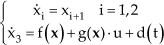
Consider a general nonlinear system:

where
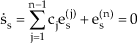
According to sliding mode control design theory, we introduce the synchronization error and determine the sliding surface of the synchronous smooth sliding mode control as:

where es is the synchronization error, c1,c2,···cn-1 are the adjustable positive constants.
The design of the synchronous smooth sliding mode control algorithm should satisfy the sliding condition, as follows:

After the system enters the sliding mode, there is:
From (19), (20) and (22), the equivalent control term ueq can be obtained as:

where ei-1 and ei+1 are, respectively, the tracking errors of the adjacent branches.
From (16), the synchronous smooth sliding mode control law can be designed as:

where γ is an adjustable positive constant, ss is the predefined sliding function as shown in (20), and γss is used to overcome the system coupling effect and the other uncertainties.
Since the sliding mode control is insensitive to the changes of the system parameters within a certain range, for the branch model (14) of the 6-PTRT parallel mechanism, f(

where Ki is the current feedback gain, Ka is the power amplifier gain, Kpre is the speed loop gain, Kv is the velocity feedback coefficient, RP (Ω) is the winding resistance of the AC servo motor, Lp (H) is the winding inductance, Ktp (N·m/A) is the torque constant, and J (kg·m2) is the total rotational inertia of the AC servo motor axis.
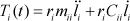
For the 6-PTRT parallel mechanism, according to (14) and (25), the sliding function of the synchronous smooth sliding mode control can be chosen as:

The synchronous smooth sliding mode control law of each branch is designed as:
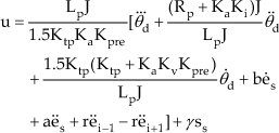
where θd is the desired angular displacement of each branch.
The stability proof is as follows.
Define the Lyapunov function as
From (26), we have:

Then:

From (18), there is:

And:

Substitute (25), (27), (29) and (30) into (28), we have

Since γ is a positive constant,
4. Simulation Experiments and Analysis of Results
The designed control system for a 6-PTRT parallel mechanism is simulated in MATLAB. The moving platform is required to move from work space (5mm, 5mm, 5mm, 0°, 0°, 0°) to work space (25mm, 25mm, 25mm, 5°, 5°, 5°) in 2s. After finishing the cycloidal trajectory planning and pose inverse solution, we can get the desired trajectories of the sliders of the six branches, and then the desired rotation angles of the motors can be obtained according to the ball screw pitch h=5mm, as follows:

According to the types of the motors and the settings of the servo amplifiers, the parameters in (27) are: J=0.318 kg·m2, Lp =0.0099H, RP=3.7Ω, Kpre =11, Kv =0.49, Ki =2.6, Ka =2, Ktp =0.67N·m/A. By the simulation adjustment, the parameters in the control law are selected as a = 707, b = 250000, γ = 1000, r=0.05. Figure 4 shows the tracking curves of the parallel mechanism control system with a coupling effect when adopting the synchronous smooth sliding mode control while Figure 5 shows the control output u of branch 1.

The tracking curves with the coupling effect
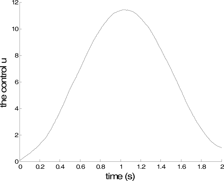
The control u of branch 1
Figure 4 shows that the parallel mechanism system for adopting the synchronous smooth sliding mode control has a high dynamic tracking accuracy and response speed. From Figure 5, we can see that the control system is smooth and chattering-free.
Figure 6 shows the tracking errors of the parallel mechanism system for adopting the smooth sliding mode control (taking branch 1 and branch 2, for example). Figure 7 shows the tracking errors of the parallel mechanism system for adopting the synchronous smooth sliding mode control (taking branch 1 and branch 2, for example).

The tracking error curves of the smooth sliding mode control

The tracking error curves of the synchronous smooth sliding mode control
From Figure 6, we can see that, in adopting the smooth sliding mode control, the state of branch 1 approaches stability after an adjusting time of 0.25s and its steady state error is less than 1.1×10⁻⁵rad; the state of branch 2 approaches stability after an adjusting time of 0.35s and its steady state error is less than 8.6×10⁻⁶rad. Figure 7 shows that, in adopting the synchronous smooth sliding mode control, the state of branch 1 approaches stability after an adjusting time of 0.1s and its steady state error is less than 1.0×10⁻⁷rad; the state of branch 2 also approaches stability after 0.1s and its steady state error is less than 2.4×10⁻⁷rad. In comparing Figure 6 with Figure 7, it can be seen that the synchronous smooth sliding mode control based on the synchronization error for the parallel mechanism with the coupling effects has the shorter response time and higher control precision. Because of the adoption of the synchronization error, which contains both the error of this branch and the errors of the adjacent branches, the tracking errors of all the branches converge on zero almost at the same time, and the movements of the parallel mechanism's branches are more synchronous and coordinated in adopting the synchronous smooth sliding mode control compared with the smooth sliding mode control.
5. Conclusions
In order to solve the coupling problem of the parallel mechanism and enhance its motion control performances, for a 6-PTRT parallel mechanism, a novel smooth sliding mode control based on a synchronization error is proposed and the system stability is proven - in theory - according to Lyapunov stability theorem. The simulation results of the 6-PTRT parallel mechanism system show that:
The synchronous sliding mode control proposed in this paper has a shorter response time and higher control precision when compared with the smooth sliding mode control.
The synchronous smooth sliding mode control which takes the errors of the adjacent branches into account is an effective solution to the coupling problem among the branches of the parallel mechanism. The designed control system can improve the synchronous coordination among the branches of the parallel mechanism with the coupling effect.
Footnotes
6. Acknowledgments
This work was financially supported by the National Natural Science Foundation of China (Grant NO. 51075222/E050101), the Priority Academic Programme Development of Jiangsu Higher Education Institutions (NO. 6, 2011) and Zhenjiang Municipal Key Technology R&D Programme (Grant No. NY2011013).