
Abstract
A wheelchair user makes direct contact with the wheelchair seat, which serves as the interface between the user and the wheelchair, for much of any given day. Seat adjustment design is of crucial importance in providing proper seating posture and comfort. This paper presents a multiple-DOF (degrees of freedom) seat adjustment mechanism, which is intended to increase the independence of the wheelchair user while maintaining a concise structure, light weight, and intuitive control interface. This four-axis Stewart platform is capable of heaving, pitching, and swaying to provide seat elevation, tilt-in-space, and sideways movement functions. The geometry and types of joints of this mechanism are carefully arranged so that only one actuator needs to be controlled, enabling the wheelchair user to adjust the seat by simply pressing a button. The seat is also equipped with soft pressure-sensing pads to provide pressure management by adjusting the seat mechanism once continuous and concentrated pressure is detected. Finally, by comparing with the manual wheelchair, the proposed mechanism demonstrated the easier and more convenient operation with less effort for transfer assistance.
1. Introduction
Many elderly people have mobility impairment that requires them to use a wheelchair. In addition to providing mobility assistance, seat adjustment design is of crucial importance in a wheelchair. A wheelchair user makes direct contact with the seat, which serves as the interface between the user and the wheelchair, for much of a given day. Tolerico et al. [1] studied the use of manual wheelchairs for daily living in the home. They found that wheelchair users spent 8.3 ± 3.3 hours daily sitting on the wheelchair. Sonenblum et al. [2] measured 25 non-ambulatory, full-time power wheelchair users and indicated that the median of the daily time sitting on the wheelchair was 10.6 hours. Souza et al. [3] examined 50 journal articles on mobility assistive technology (MAT) and concluded that electrical wheelchairs should be considered not only as providing mobility for advanced stages but as mobility assistive technology that can be integrated with an adjustable seating system to reduce fatigue.
To enable functional independence for older adults who use a wheelchair, their posture and comfort should be considered. Redford [4] reviewed studies specifically concerned with seating and wheeled mobility for older adults, and concluded that these users would benefit from the matching of mobility to function, cheaper and more effective cushions, more modular seating systems, and better lifting and transfer. Among the considerations in wheelchair seat design, pressure management received the most attention. Sitting-acquired pressure ulcers are a significant healthcare problem for wheelchair users. Various seating designs have been proposed for maintaining tissue viability while the user is in the wheelchair. For example, air cells with pressure sensors to monitor the pressure distribution on the buttock are often utilized to provide timely adjustment of the shape of the seat cushion to relieve concentrated pressure [5–7]. “Dynamic seating” on the wheelchair, in which a power-operated seat adjustment mechanism would allow the user to maintain proper posture, was also proposed [8].
Tilt-in-space, backrest recline, and seat elevation are the seat adjustment functions of electrical wheelchairs most prescribed by clinicians to facilitate posture change and/or assist activities of daily living (ADL) for users [9,10]. Ding et al. [11] surveyed the real-life usage of powered seating functions among wheelchair users during their daily activities. The results showed that subjects accessed tilt-in-space, backrest recline, and seat elevation 19 ± 14 ×, 12 ± 8 ×, and 4 ± 4 × per day, respectively. Further, of the time participants spent in a wheelchair, 39.3% ± 36.5% was in the tilted or reclined positions. Lacoste et al. [12] interviewed 40 participants at home and reported that 97.5% used the powered tilt-in-space and/or recline function in a given day, and that 70% used the functions primarily to rest, relax, increase comfort, and decrease pain.
Many studies have been conducted to evaluate seat pressures at different angles of the tilt-in-space function in laboratory settings. Sprigle et al. [13] found that the tilt-in-space function reduced static seating pressure significantly, which could be a key factor in pressure ulcer prevention. In addition, many laboratory-based studies suggested that large tilt-in-space angles can be used to manage seating pressure to reduce the risk of pressure ulcers [5, 14]. Aissaoui et al. [15] concluded that the maximum pressure reduction at ischial tuberosities was at 45° of tilt-in-space.
In addition to providing seating comfort and pressure management, the seat elevation function for wheelchair users is considered medically necessary [16, 17]. The seat elevation feature can help wheelchair users accomplish mobility-related ADL, such as performing transfers and reaching objects at different heights to preserve upper-limb functions and to achieve eye contact in social situations.
A search of related patents indicated that most seat adjustment functions for wheelchairs applied linkage mechanisms [18–20]. Additionally, some linkage mechanisms were implemented with actuators or motors to provide multiple degrees of freedom (DOF) in seat adjustment. Bae and Moon [21] designed a wheelchair seat mechanism using four actuators to achieve the forward/backward tilting, elevation, and standing motions. The seat mechanism is composed of four independent adjustment mechanisms, each of which is driven by an actuator. Wada [22] used a linear drive unit to develop a chair tilting system for the climbing wheelchair to maintain the angle between the seat and the floor. Lee et al. [23] developed a seat adjustment mechanism that is integrated with the frame of the wheelchair to increase stability by shifting the centre of gravity. The mechanism also provided a tilt-in-space function. Koontz et al. [24] evaluated 109 manual wheelchairs, 89 electrical wheelchairs, and 15 scooters for manoeuvrability. They concluded that the angles produced by the tilt-in-space and recline functions lengthen electrical wheelchairs and therefore increase the space needed for manoeuvring. Weight and complexity of the wheelchair is also increased with the multiple-DOF seat adjustment functions.
Transfer activities mainly determine the degree of independence attainable by wheelchair users in daily living. Among all transfer activities, sitting pivot transfer (SPT) is the most commonly used [25–28]. The basic steps of SPT are moving the buttocks toward the edge of the initial surface, placing the feet in a stable position, and leaving one hand on the initial surface (trailing) while placing the other hand on the target surface (leading). The arms are used to push up from the initial surface and pivot the body on the feet, swinging and landing the buttocks onto the target surface [29]. However, proper transfer technique may not be sufficient when wheelchair users encounter height differences and gaps crossing between wheelchair and target surface [30].
Few studies have examined the development of a transfer assist function of a wheelchair. Khatchadourian et al. [31] used robotic technologies to develop a mobile robot modelled on a forklift for users to perform transfer activities. The user uses a beacon to position the mobile robot close to him or her. Then, the user can apply force to the support arms of the lifting mechanism to relocate himself or herself into the mobile robot. Bostelman and Albus [32] built a “Home Lift, Position and Rehabilitation (HLPR) Chair” to provide independent mobility and transfer activities assistance for the user in an indoor environment. However, the size (1,450×580×1,780 mm in mobility configuration, 1,450×580×2,410 mm in full lifted configuration) and weight (136 kg) of the HLPR chair may make it impractical for the home.
Miller and Slack [33] were the first to use the term “robotic wheelchair.” They built two prototypes of robotic wheelchairs that used various sensing and navigation technologies that are often used in robotics. These wheelchairs were able to assist users to pass through narrow paths and avoid obstacles. Simpson [34] reviewed the many recent studies on the development of “smart wheelchairs” that can perform somewhat autonomously.
This paper presents the multiple-DOF seat adjustment mechanism of the “intelligent Robotic Wheelchair” (iRW). The features of the iRW include (1) four Mecanum wheels to facilitate movement in all directions and zero radius of rotation, (2) mobility assistance functions that can be invoked by the wheelchair user, caregivers, or the iRW itself, and (3) an information/communication module that monitors selected health indicators and provides user access to the internet. The seat adjustment mechanism of the iRW is achieved by a four-axis Stewart platform. The Stewart platform [35] is a parallel structure robot that has greater stiffness, positioning accuracy, and payload-to-weight ratio than serial structure robots.
The multiple-DOF seat adjustment mechanism developed in this research is capable of heaving, pitching, and swaying to provide a comfortable sitting posture, a seat elevation adjustment function, and transfer activities assistance. Special consideration is paid to arranging the actuators to reduce the control complexity of the parallel mechanism, so that the wheelchair user can make the seat adjustment by simply pressing a button. Equipped with soft pressure-sensing pads, the seat also provides pressure management by adjusting the seat mechanism when continuous, concentrated pressure is detected.
The rest of the paper is organized as follows. Section 2 proposes the design concept of the multiple-DOF seat adjustment mechanism. Section 3 discusses the simulation of the multiple-DOF seat adjustment mechanism on the iRW. Section 4 describes the control scheme and test results of the seat adjustment mechanism. Finally, Section 5 concludes the paper.
2. Design Concept of the Multiple-Degrees-of-Freedom Seat Adjustment Mechanism
The literature review in Section 1 indicated that a wheelchair seat adjustment mechanism should meet the following design requirements:
2.1. Tilt-in-space
Tilt-in-space is important for pressure management and comfortable sitting posture. Aissaoui et al. [15] found that an effective weight shift could be achieved when the tilt-in-space angle was at least 15°. Sonenblum et al. [36] evaluated 10 participants and found that none required an angle of tilt-in-space function as great as 20°. Ding et al. [11] concluded from a survey that the most often-used ranges of tilt-in-space angles were 2.5° to 10°, followed by 10° to 20°, and their frequency and time were 6.6 ± 4.9 × for 272.7 ± 228.7 minutes and 7.3 ± 6.6 × for 157.3 ± 171.8 minutes a day. Based on the literature above, the range of tilt-in-space angle of the iRW was set to 20°.
2.2. Seat elevation / Sideways movement
The capabilities of adjusting seat elevation and sideways movement by the wheelchair user enhance transfer activities assistance. Seat elevation adjustment is used to reduce the height difference when performing transfer activities. To accommodate the height of facilities in the living environment where transfer activities often occur, e.g., a range in height of a toilet from 279 to 432 mm and of a bed from 430 to 485 mm [37], the seat elevation adjustment of the iRW ranges from 370 to 490 mm. The seat can move sideways by a maximum of 150 mm, which is believed sufficient to cover the gap when crossing between wheelchair and target surface.
2.3. Practical considerations
Besides the functional requirements, the size, weight, and control complexity of the adjustment mechanism were considered. The specifications for 16 models of electrical wheelchairs commercially available in Taiwan were examined; their average size was 910×640 mm (L×W). These dimensions were taken as the upper limit for the iRW. Moreover, the wheelchair user should be able to make the seat adjustment in all DOFs by simply pressing a button, and to stop the seat movement by releasing the button.
The seat adjustment mechanism of the iRW is based on the Stewart platform. The seat adjustment mechanism has three DOFs: heave, sway, and pitch. These facilitate tilt-in-space, seat elevation, and moving sideways.
The Stewart platform has been used in flight simulators [38], machine tools [39], a biped locomotion system [40] and surgery manipulators [41, 42]. The Stewart platform, illustrated in Figure 1, is composed of a fixed base, a movable platform, and six linear actuators connecting the fixed base to the movable platform. This is a six-DOF universal-prismatic-spherical mechanism, which supports heave, surge, sway, yaw, pitch, and roll. No additional structural members are needed in the Stewart platform because the actuators also function as structural members. One drawback of the Stewart platform is the small workspace. Another is complexity of control, which is due to the need to control six linear actuators simultaneously in a nonlinear manner and to the existence of singular positions.

Schematic diagram and degrees of freedom of Stewart platform
In this research, the Stewart platform is converted into a multiple-DOF seat adjustment mechanism, as shown in Figure 2. The seat acts as the movable platform of the Stewart platform, and the h-shape structure of the omni-directional moving vehicle of the iRW acts as the fixed base of the Stewart platform. The number of linear actuators is reduced from six to four because only three DOFs (heave, pitch, and sway) of seat adjustments are required. The seat and actuators are connected with universal joints, and the omni-directional moving vehicle and actuators are coupled with two revolute joints and two universal joints.

The multiple-DOF seat adjustment mechanism of the iRW
Figure 3 depicts the multiple-DOF seat adjustment mechanism of the iRW. Actuators 1 and 2 are fixed at an incline of 20° from the y-z plane. Actuators 1 and 2 extend or retract at the same constant speed to provide a smooth adjustment. An offset angle (7.4°) between Actuators 1 and 2 and the z-axis provides a horizontal force component when swaying sideways (i.e., in the +y direction). Actuators 3 and 4 are fixed at an incline of 20° from the y-z plane. The offset angle (7.4°) and direction (+y direction) of Actuator 4 are the same as for Actuators 1 and 2. To constrain the DOFs, the offset angle between Actuator 3 and the z-axis, 10.6°, differs from that of the other actuators.

The multiple-DOF seat adjustment mechanism in front and side view
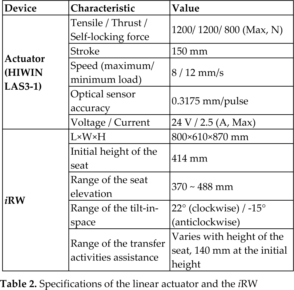
Table 1 shows the coordinated actions of actuators when the seat is adjusted. For example, when raising the seat, Actuators 1 and 2 retract and Actuators 3 and 4 extend. When adjusting the seat to the right, Actuators 1, 2, and 4 extend and Actuator 3 retracts. In this setup, the initial height of the seat is 414 mm. The range of height adjustment is from 370 mm to 488 mm, limited by the stroke of the actuators. The range of tilt-in-space angle is from −15° to 22°. The −15° tilt-in-space can be used in sit-to-stand assistance. The range of sideways movement varies with the height of the seat. At the initial height of 414 mm, the range of moving sideways is 140 mm. Table 2 shows the fundamental specifications of the linear actuators and the iRW.
Coordinated actions of actuators

Specifications of the linear actuator and the iRW
3. Simulation of the Multiple-Degrees-of-Freedom Seat Adjustment Mechanism
As shown in Figure 4, Actuators 1, 2, and 4 are designed to extend or retract at the same constant speed when the wheelchair user pushes a button to perform tilt-in-space, change elevation, or move sideways. Actuator 3 is the only actuator that has to be controlled in a nonlinear manner to maintain the seat in a horizontal orientation when adjusting elevation or moving sideways.

Simulation of seat elevation
This section presents the results of using SimWise 4D ver. 8.0.2 to examine how the motion of the seat was affected by the length of each actuator. This simulation also confirmed the ranges of the seat adjustment described in Table 2.
Figure 4 shows the simulation result of adjusting seat elevation from 370 mm to 488 mm in 10 seconds. The origin represents the centre of the seat. Figure 4(a) shows that the motion of all actuators appears to be linear. In particular, the lengths of Actuators 1 and 2 remained equal throughout, and the change in their length was inverse to the change in length of Actuator 4. Figure 4(b) shows that the seat moved slightly forward or backward (i.e., along the x-axis) when the height of the seat was changed. The range of this movement distance along the x-axis was 43 mm.
Figure 5 shows the simulation result of the tilt-in-space at the initial height, from −15° (anticlockwise) to 22° (clockwise) in 10 seconds. Figure 5(a) indicates that the change in length of all actuators appears to be linear. In particular, the lengths of Actuators 1, 2, and 4 remain equal. Figure 5(b) shows that the seat maintains a constant horizontal orientation within the y- and z-axes while undergoing tilt-in-space along the x-axis.

Simulation of tilt-in-space
Figure 6 shows the simulation result of the seat moving sideways 140 mm from its initial position. Figure 6(a) indicates that the lengths of Actuators 1, 2, and 4 remain equal throughout, while the length of Actuator 3 varies nonlinearly. Figure 6(b) shows that the seat itself maintains a constant horizontal orientation (z- and x-axes) while moving sideways in the +y direction.

Simulation of sideways movement
In all three simulations, the absolute values of the speeds of Actuators 1, 2, and 4 remained constant. This simplifies the design of the control scheme, which is discussed in the next section.
4. Control Scheme for the Multiple-Degrees-of-Freedom Seat Adjustment Mechanism
On the iRW, the user would adjust the seat by pushing one of three buttons located on the armrest, which correspond to tilt-in-space, seat elevation adjustment, or sideways movement. Actuators 1, 2, and 4 would always extend/retract at a pre-set constant speed. The extend/retract speed of Actuator 3 would be calculated by an Arduino microcontroller.
Figure 7 shows how the speed of Actuator 3 would be derived when the seat moves sideways. The coordinates of the joints of the four actuators on the fixed base and the position of the movable platform (the seat) are known. There is an optical sensor in each actuator that detects its current stroke, i.e., the amount of extension of the actuator. As shown in Figure 7, the current coordinates of the joint of Actuator 3 at the movable platform J3, expressed as (x3, y3, z3), can then be calculated. When the wheelchair user pushes a button to move the seat sideways, Actuators 1, 2, and 4 start to extend at the same constant speed. After a small interval of time Δt, the coordinate of J3 would need to become (x3, y3 + Δy, z3), which is calculated from the expected changes of the strokes of Actuators 1, 2, and 4 after this time interval. In the program in the Arduino microprocessor, Δt = 0.04 seconds (25 Hz). The expected change of the stroke of Actuator 3 can then be easily calculated and expressed as a “speed ratio” of Actuator 3 to Actuators 1, 2 or 4. This “speed ratio” is then implemented in the pulse-width modulation (PWM) control of the Arduino microcontroller, in which the motor speed control is digitized on a scale of 0~255. The movement stops when the wheelchair user releases the button, or when one of the actuators reaches its limit.

Derivation of the speed of Actuator 3 when the seat moves sideways
The seat control scheme was implemented in a prototype. A test was performed to confirm that the seat maintains a constant orientation when it is being adjusted. A tri-axial accelerometer module (KXPA4-2050, Kionix) set up at the centre of the seat was used to detect its orientation.
The accelerometer module has a built-in low-pass filter at the cut-off frequency of 50 Hz. The module's sensing range along each axis is ±2 g, and its output varies with acceleration at the rate of 660 mV/g. If there is no acceleration applied along an axis, the output voltage Voff equals half Vdd (3.3 V). If acceleration A exists toward the positive direction, the output voltage increases (Vout > Voff) and vice versa. Equation (1) shows the relation:

Tilt/inclination sensing is a common application for low-g accelerometers. Figure 8 indicates the tilt angles (pitch and roll) of the seat, where φ, ρ, and θ represent the tilt angles with respect to the x-, y-, and z-axes relative to ground. Equation (2) identifies the relation between the tilt angles and accelerations along each axis. Note that in pitch, θ + φ = 90°, while in roll, θ +ρ= 90°.

Pitch and roll represented as changes in angle along the coordinate axes

In the initial setup, the height of the seat is 414 mm and the angle φ is +5°. As shown in Figure 9, two conditions were considered: when the seat was empty (continuous lines) and when the seat was loaded with a 70 kg mass (short dash lines). Figure 9(a) shows the values of the tilt angles while the seat elevation is raised from 370 mm to 488 mm over about 8 seconds. The angle φ obtained from the accelerometer module was maintained at 4.73° ± 0.43° to ground, while angle θ was maintained at 85.21° ± 0.44° to ground during the elevation process. When the seat was loaded with the mass, the angle φ obtained was 4.26° ± 1.70° to ground. Figure 9(b) shows the values of the tilt angles while the seat's tilt-in-space is changing from −15° to 22° over about 8 seconds. Note that when θ exceeds 90°, the arctan function in Equation (2) will generate a θ value less than 90°. Therefore, both the arctan value and the true angle θ are displayed in Figure 9(b). Figure 9(c) shows the values of the tilt angles while the seat, which is maintained at the initial height of 414 mm, is being adjusted sideways from 0 mm to 140 mm over about 8 seconds. The angle φ was maintained at 6.14° ± 0.24° when there was no mass loaded on the seat. When the seat was loaded, the angle φ was maintained at 5.61° ± 1.84°. The results depicted in Figure 9 indicate that the orientation of the seat remained stable when using the proposed control scheme, though the 70 kg mass had some effect on the stability.
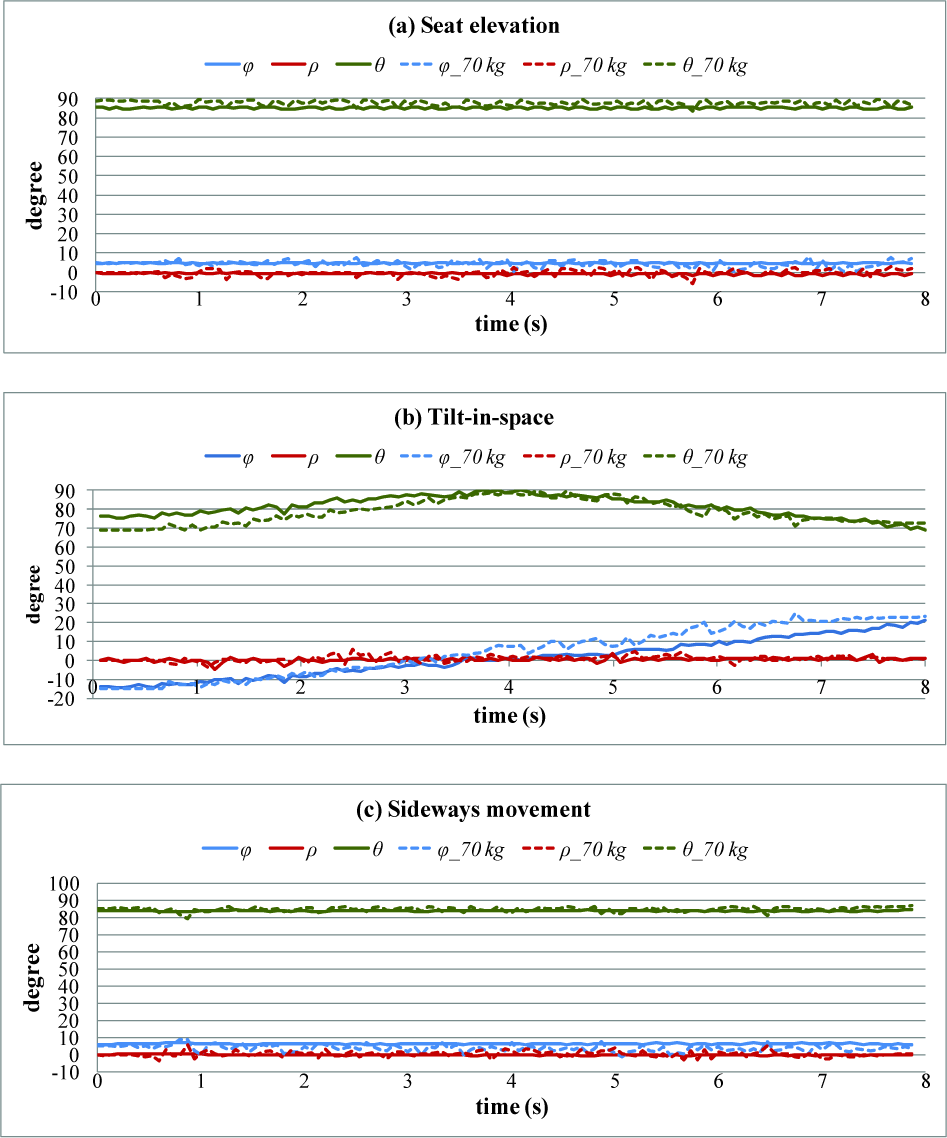
Resulting values of the tilt angles for each type of seat movement
Figure 10 depicts the flow chart for processing a user's pressing a button to move the seat. To avoid different functions disrupting each other and to foster safety, there are three basic rules in the control flow:
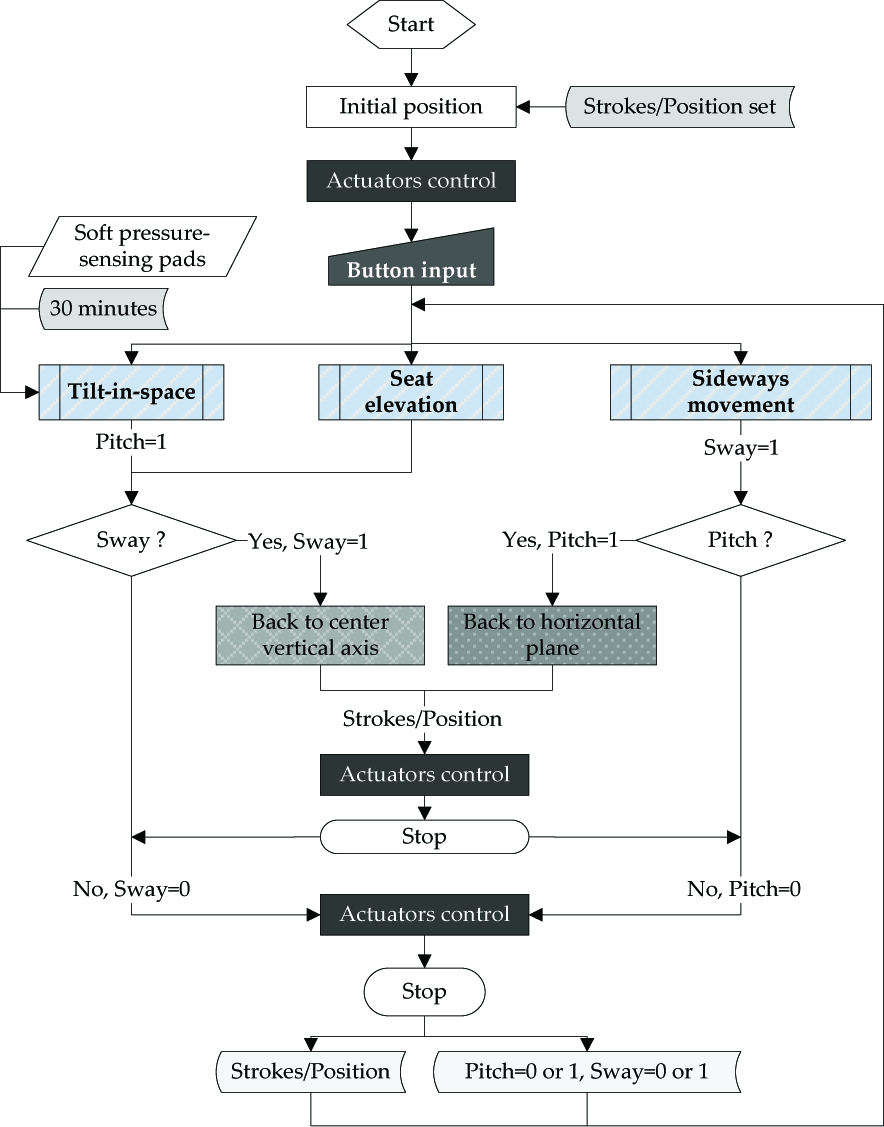
Flow chart for processing a user's pressing a button to move the seat
Only one function can be performed at a time. If two buttons are pressed at the same time by the wheelchair user, neither function will operate.
To start seat elevation adjustment or the tilt-in-space function, the distance of sideways movement has to be zero. If this distance is not zero, the seat will automatically move back to the centre vertical axis, after which the requested movement will be carried out.
To start sideways movement, the angle of tilt-in-space has to be zero. If this angle is not zero, the seat will automatically move back to the horizontal plane while maintaining its height, after which the requested movement will be carried out.
The seat also provides a pressure management function by automatically adjusting the tilt-in-space when continuous, concentrated pressure is detected by the soft pressure-sensing pads. As shown in the flowchart in Figure 10, when no buttons are pressed, if the pressure distribution is not changed in 30 minutes, the tilt-in-space function will automatically start to increase (or decrease) seat angle by five degrees in 60 seconds. The pressure management function will be interrupted if the wheelchair user pushes any button during the 60 seconds.
5. User evaluation of the transfer assistance function provided by the iRW
As described in the first section, it has been shown in previous studies that the adjustability of the tilt-in-space angles of a wheelchair can help to relieve seating pressure and improves seating comfort. However, there is little evidence supporting how elevation and sideways movement may benefit wheelchair users in transfer assistance. Thus, in this study, the usability of the transfer assistance function provided by the iRW was evaluated and compared with that of a standard manual wheelchair.
Six healthy participants (three males and three females, an average of 22.8 years old) were recruited for user evaluation. Each participant was requested to perform the same transfer activities with the iRW and then with a manual wheelchair, by simulating how one moves from either the iRW or the manual wheelchair to a piece of furniture in the home environment, as well as returning to the iRW or the manual wheelchair. While using the iRW, the participant may use the elevation adjustment and sideways movement functions to facilitate the transfer activities. As for the transfer activities with the manual wheelchair, the participant can use a transfer board. In order to investigate the effectiveness of the seat elevation adjustment and sideways movement functions of the iRW, two conditions of transfer activities were considered. In the first part of the evaluation, the iRW, manual wheelchair, and the target plane were at the same height of 45 cm. In other words, the participant transfers between two planes with the same height, by using the sideways movement function of the iRW or the transfer board with the manual wheelchair. In the second part of the evaluation, the height of the target plane was 50 cm, while the heights of the seat pans of the iRW and the manual wheelchair were both 45 cm. Thus, the participant needs to use the seat elevation adjustment and sideways movement functions of the iRW or the transfer board with the manual wheelchair to move between two planes with different height levels. The steps of the evaluation are described as follows.
Spending 5 minutes to become familiar with the operation of the elevation adjustment and sideways movement functions of the iRW and the use of a transfer board with the manual wheelchair.
Part I
Crossing a horizontal gap of 15 cm to transfer from the iRW (with the seat height set at 45 cm) to the target plane of height 45 cm by using the sideways movement function to move as close as possible to the target plane.
Transferring back from the target plane to the seat pan of iRW and using the sideways movement function to return the seat to the default position.
Repeating step 2 and step 3 five times.
Repeating steps 2 to 4 with the manual wheelchair by using the transfer board to cover the gap to perform transfer activities.
Filling the questionnaire to collect the subjective responses toward the usability of the iRW and the manual wheelchair for transfer activities.
Part II
Crossing a horizontal gap of 15 cm to transfer from the iRW (with the seat height set at 39 cm) to the target plane with the height of 50 cm by using the elevation adjustment and sideways movement functions to move as close as possible to the target plane.
Transferring back from the target plane to the iRW and using the sideways movement function to return the seat to the default position.
Repeating step 7 and step 8 five times.
Repeating steps 7 to 9 with the manual wheelchair by using the transfer board to cover the gap to perform transfer activities.
Filling in the questionnaire to collect the subjective responses on the usability of the iRW and the manual wheelchair for transfer activities.
The operation time required for the transfer activities with the iRW and the manual wheelchair were measured and compared. Figure 11 shows the average operation time for the different transfer activities with both mobility aids. While transferring to the target plane of 45 cm (Part I), participants took a significantly shorter time to perform transfer activities with the iRW than the manual wheelchair (p = 0 < α = 0.05). Further, there was a significant difference in operation time among participants when transferring from the iRW to the target plane (p = 0.0006 < α = 0.05). This may be due to preference in determining the sufficient proximity for the individual to move. In addition, while transferring from the target plane to the iRW, no significant difference was found in operation time among participants (p = 0.20 > α = 0.05). This is because, when returning to the default position, the seat of the iRW will move to the destination automatically once the button is pressed. In other words, user adjustment is not required, and individual difference will not therefore not affect the operation time much. On the other hand, no significant difference was found in operation time among the participants while using the manual wheelchair to perform the transfer activities in both directions (to the target plane: p = 0.06 > α = 0.05; to the wheelchair: p = 0.36 > α = 0.05). The results imply that the iRW provided a better efficiency for transfer assistance than the manual wheelchair did. In addition, individual difference in operation efficiency was found while using the sideways movement function of the iRW, but it was not observed when using a transfer board with a manual wheelchair.
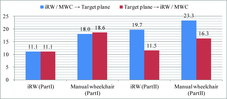
The average transfer activities time of each step
When the height of the target plane was 50 cm (Part II), the participants also took a significantly shorter time to transfer to the target plane by using the iRW than the manual wheelchair (p = 0.004 < α = 0.01). When transferring from the iRW to the target plane, there is also a significant difference in operation time among participants (p = 0.02 < α = 0.05). In this case, the possible reason is the preference of height and distance differences between the seat pan and the target plane for the safe transfer. However, when transferring back to the iRW, there was no significant difference in operation time among participants (p = 0.06 > α = 0.05). Again, this is because the seat of the iRW will move to the destination automatically once the button is pressed. On the other hand, while using the manual wheelchair to perform the transfer activities, there were significant differences in operation time among participants in both directions (to platform: p = 0.001 < α = 0.05; from platform: p = 0 < α = 0.05). This might be caused by the height difference between the seat pan of the manual wheelchair and the target plane. For people with different skills and experiences, the time required for climbing up or sliding down to another plane with a different height may differ.
As for the subjective responses, the 5-point scale was first used to evaluate the user satisfaction (1 = very dissatisfied; 5 = very satisfied) toward the iRW. The participants generally felt satisfied with the safety (average score = 3.7) and stability (average score = 3.5) while moving the seat of the iRW up and down and in sideways. In addition, the 5-point scale was adopted to investigate how the participants feel whether the transfer assistance provided by the iRW or the manual wheelchair fits their needs (1 = not at all; 5 = very much). The participants reported that the seat elevation adjustment and sideways movement functions of the iRW (average score = 4.3) fitted their needs for transfer activities better than the combination of the transfer board and the manual wheelchair did (average score = 3.0; p = 0.006), no matter whether there was a height difference between the two planes.
On the other hand, the 5-point scale was further used to evaluate the level of easiness (1 = very difficult; 5 = very easy) and the level of convenience (1 = very inconvenient; 5 = very convenient) toward the transfer assistance provided by the iRW and the manual wheelchair. Besides, the Borg CR-10 scale [43] was adopted to measure the exercise intensity levels (0 = nothing at all; 3 = moderate; 10 = very very hard) while using the iRW and the manual wheelchair for transfer. The statistics in the two parts of evaluation (“to the target plane” and “from the target plane”) are presented and discussed as follows.
In the first part of the evaluation, the participants felt the iRW can make the transfer activities slightly easier (4.0 for the iRW; 3.3 for the manual wheelchair; p = 0.07) and significantly more convenient (4.2 for the iRW; 2.5 for the manual wheelchair; p = 0.01) than the manual wheelchair in both directions, as shown in Table 3. Moreover, the participants reported a significantly lower exercise intensity while operating the iRW (average score = 2.5) than the manual wheelchair (average score = 4.5; p = 0.02) in both directions. The results demonstrate that the iRW can help the user to perform transfer activities between two planes at the same height with better convenience and less effort than the manual wheelchair.
Statistics of the subjective responses toward the transfer activities at the same height (Part I)

significant difference (p < 0.05) between the iRW and the manual wheelchair (MWC)
In the second part of the evaluation, the iRW assisted the participants to transfer to the higher target plane significantly more easily (3.8 for the iRW; 2.6 for the manual wheelchair; p = 0.02) and significantly more conveniently (4.3 for the iRW; 2.6 for the manual wheelchair; p = 0.008) than the manual wheelchair, as shown in Table 4. While transferring back from the target plane, there was no difference in easiness (3.5 for the iRW; 3.8 for the manual wheelchair; p = 0.24) and convenience (3.8 for the iRW; 3.3 for the manual wheelchair; p = 0.25) between the two mobility aids. The possible reason is that transferring from the higher target plane to the manual wheelchair was enabled by sliding down through the transfer board, which makes it easier and more convenient than climbing up. Regarding the exercise intensity of the transfer activities, the participants reported a significantly lower intensity with the iRW (average score = 3.0) than the manual wheelchair (average score = 5.2; p = 0.03) while transferring to the target plane. When transferring back from the target plane, the participants perceived a slightly lower intensity with the iRW (average score = 3.0) than the manual wheelchair (average score = 4.7; p = 0.05). The results reveal that the iRW can help the user to perform transfer activities from a plane to another higher one with more ease, better convenience, and less effort than the manual wheelchair.
Statistics of the subjective responses toward the transfer activities at different heights (Part II)

:significant difference (p < 0.05) between the iRW and the manual wheelchair (MWC)
6. Conclusion
Seat adjustment design is of crucial importance to a wheelchair user. This paper presents the development of a multiple-DOF seat adjustment mechanism achieved by a four-axis Stewart platform, which is capable of adjustment in tilt-in-space, seat elevation, and sideways movement to support the needs of the wheelchair user at home, including comfortable sitting posture, pressure management, and transfer activities assistance. The actuators are carefully arranged so that only one actuator needs to be controlled, enabling the wheelchair user to adjust the seat by simply pressing a button. Figure 12 shows the prototype of the iRW. The size of the iRW prototype is 800×610×300 mm, and the total weight is 28 kg, which is practical to be used in the home environment. A memory foam seat, which helps to relieve body pressure for better comfort, rests on the multiple-DOF seat adjustment mechanism. The armrests can be opened outward during transfer assistance.

Prototype of the iRW
This multiple-DOF seat adjustment mechanism is intended to increase the independence of the wheelchair user while maintaining a concise structure, light weight, and intuitive control interface. From the orientation confirmed test, the 70 kg mass has slight effect on the stability. However, the user felt safe and stable while adjusting the seat of the iRW. Besides, it was demonstrated that the seat adjustment functions of the iRW can help the user to perform transfer activities more easily and more conveniently with less effort than the manual wheelchair. Furthermore, with the flexibility of applying the mechanism proposed in this study, it can be readily implemented in not only the iRW but also any other electrical wheelchair.