
Abstract
When localizing mobile sensors and actuators in indoor environments laser meters, ultrasonic meters or even image processing techniques are usually used. On the other hand, in smoky conditions, due to a fire or building collapse, once the smoke or dust density grows, optical methods are not efficient anymore. In these scenarios other type of sensors must be used, such as sonar, radar or radiofrequency signals. Indoor localization in low-visibility conditions due to smoke is one of the EU GUARDIANS [1] project goals.
The developed method aims to position a robot in front of doors, fire extinguishers and other points of interest with enough accuracy to allow a human operator to manipulate the robot's arm in order to actuate over the element. In coarse-grain localization, a fingerprinting technique based on ZigBee and WiFi signals is used, allowing the robot to navigate inside the building in order to get near the point of interest that requires manipulation. In fine-grained localization a remotely controlled programmable high intensity LED panel is used, which acts as a reference to the system in smoky conditions. Then, smoke detection and visual fine-grained localization are used to position the robot with precisely in the manipulation point (e.g., doors, valves, etc.).
1. Introduction
Achieving the localization of mobile sensors and actuators in indoor scenarios is a very active research field that requires the use of specific techniques. Due to the fact that GPS cannot be used in such scenarios [2, 3], many solutions are based on visual landmarks [4, 5] or lasers [6, 7], using in most of the cases an already existing map of the place. Once the visibility conditions are good, these techniques can work in a very accurate manner [19].
Besides this, in the scientific literature other ways to obtain the localization of a mobile sensor can be found, for example when using a wireless network to interconnect the devices. A simple and cheap method to gain the position of mobile nodes is using radio signal characteristics. Some examples of these techniques are “Time Of Arrival” (TOA), “Time Difference of Arrival” (TDoA), “Angle of Arrival” (AOA), “Received Signal Strength Indicator” (RSSI), “RSSI fingerprinting” [8, 9] and others. In particular, the TDoA method can use a radio signal combined with a sonar device. By measuring the difference in time of flight between the radio and the sonar signals, the distance between the transmitter and the receiver can be estimated in a very accurate manner [10, 11]. The proposed method for localizing the robot in smoke uses a combination of techniques to achieve maximum efficiency, depending on the smoke conditions.
1.1. Fingerprinting versus analytical localization methods
Analytical localization methods use signal attenuation of the received signal strength to calculate the distance to the transmitter. In indoor environments, signal strength may be affected by the building geometry, as well as by the materials used in walls, floors, ceilings and furniture, which seriously affects the precision of the analytical methods.
In these cases, it is possible to enhance the localization method accuracy by applying fingerprinting techniques [12, 13, 14]. This means that the system builds a radio behaviour database for the whole room, which is used afterwards to recognize the real position of a node by applying pattern recognition techniques. These methods have the drawback that building such a database is very time consuming and, moreover, requires more memory and processing power to perform the recognition in real time. On the other hand, these methods simplify the hardware of the beacons by only using a radio transmitter/receiver (e.g. ZigBee, WiFi, etc.).
2. System Description
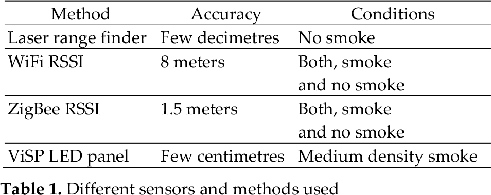
The system consists of a multisensor integration in order to get an appropriate localization of the robot during a fire intervention in an indoor scenario. Fire scenarios with a smoky atmosphere (the typical place where fireman interventions are developed) make some techniques not suitable. The developed system integrates the localization methods explained in Table 1 (with their respective estimated accuracy) and decides which one is the best depending on the smoke conditions.
When moving in a known environment, where a map can be used, with low smoke density (e.g., visibility of 5-8m) the laser range finder MCL (Monte Carlo Localization) algorithm [15] provides an easy way to navigate.
Fingerprinting techniques may be used with radiofrequency signals by placing beacons at known positions. Since the WiFi infrastructure is usually present in public buildings and even in private ones and may be used without extra cost, this technology can be useful in many situations for implementing the coarse-grained localization system. By taking into account WiFi and ZigBee transmitters we send more significant information to the recognition system.
In addition, when approaching an interest point, such as a door, a fire extinguisher etc., visual positioning [16] may be used to determine the robot's position with accuracy.
In previous works, the research team has developed fine-grained localization, combining radiofrequency and sonar with a precision of 1cm. This technique may be used to follow a fire fighter wearing the appropriate transmitter [11].
Different sensors and methods used
2.1. Hardware description
The hardware platform used in the experiments consists of a mobile robot with sensors mounted on it, as shown in Fig. 1. The robot structure is shown in Fig. 2, where one can appreciate that every sensor is connected to a PC computer installed in the robotic platform. A WiFi communications interface is used both to measure the signal strength from WiFi routers and to communicate with the external world.

Rescuer robotic platform elements description
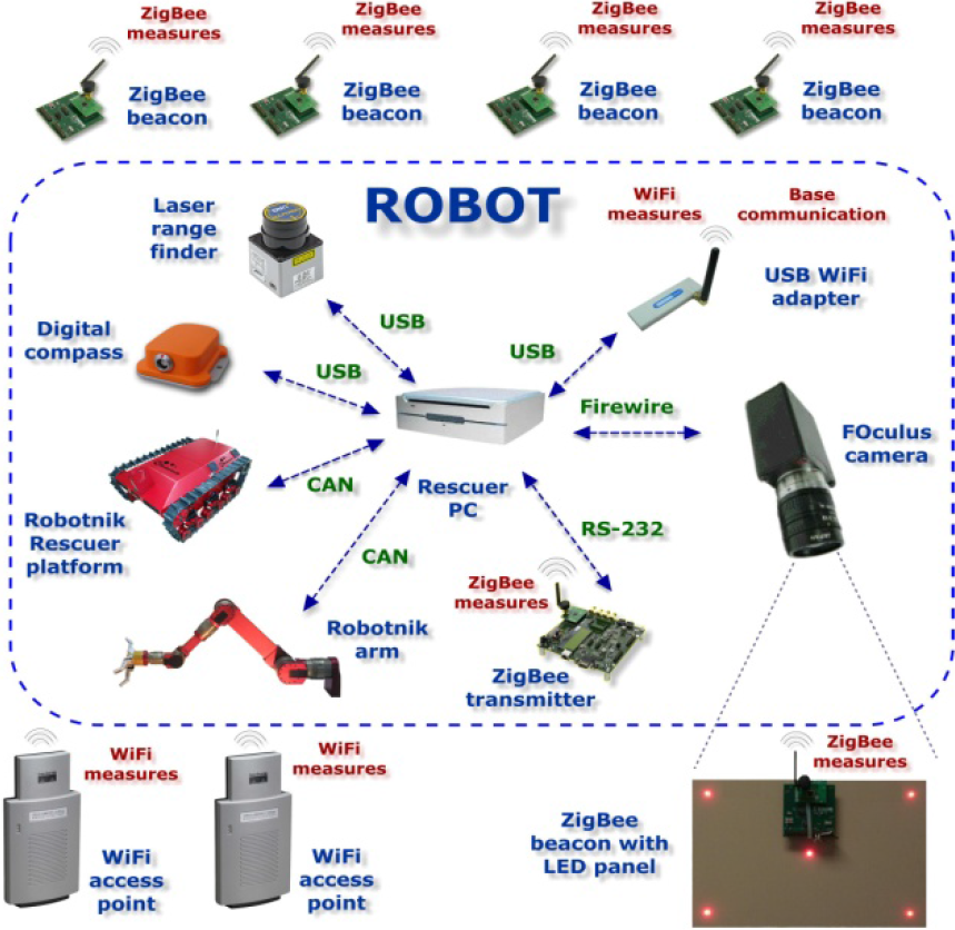
Rescuer robotic platform hardware architecture

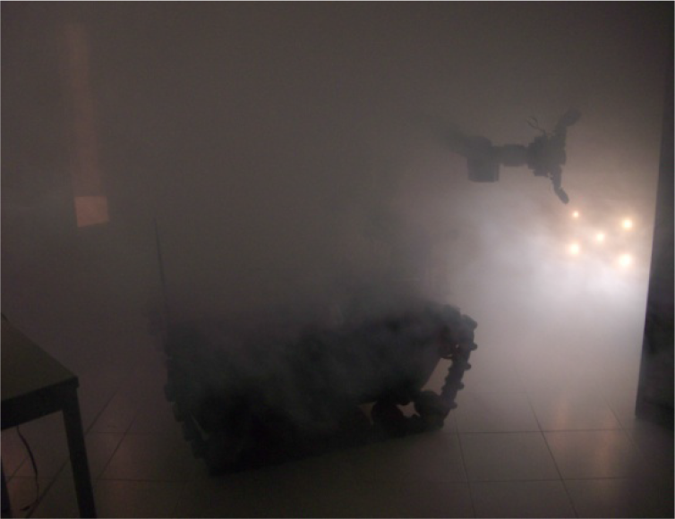
Rescuer robotic platform approaching to a high luminosity LED panel in a smoky environment for fine-grained localization
2.1.1. Map navigation
The laser range finder installed on the robot is used to measure distances to near obstacles and compare them with a building map, in order to estimate the robot's position. For this purpose, the Monte Carlo Localization method (MCL) is used [15], implemented in the Player/Stage software platform installed on the robot's PC.
Once the smoke density increases, the system is not able to recognize the wall contours with the laser anymore, so other technologies must be used, as is explained in the following section.
2.1.2. WiFi localization
The robot's PC wireless card adapter is used as a WiFi sensor. By performing a search of the available wireless networks, it is possible to obtain a list of the WiFi access points, their RF channels and the corresponding received signal strength. This information permits experiments with other kinds of localization methods, such as radiofrequency fingerprinting ones.
2.1.3. ZigBee localization
The ZigBee section of the system is based on the CC2430 and CC2431 Texas Instruments microcontrollers. Their transceivers meet the ZigBee specification, with the capacity to obtain the RSSI (Received Signal Strength Indicator) from every received packet. Moreover, 16 different channels can be configured with 256 different power levels. This has been used to increase the number of packets sent between the beacons and the mobile sensor at each robot position to improve the efficiency of the localization method, leading to a better accuracy than with WiFi transmitters, where only one channel and power level are used.
The experiments have been performed by using four transmitters in known positions (beacons) and one mobile transmitter located on top of the robotic platform (as shown in Fig. 2).
The whole sensor network information arrives at the robot's PC, which calculates its own position in real-time.
2.1.4. Visual positioning
When the robot is located near a point of interest such as a door or fire extinguisher, the system performs a fine-grained localization method to position the robot in the required place by using a programmable high luminosity LED panel. A firewire camera (FOculus FO124) has been mounted on the robot, which is operated on-board by an application running on the robot's PC, by taking an image of the LED panel. This panel acts as a landmark in order to estimate the current position of the robot by using a computer vision pose-estimation method.
As the geometry of the LED panel is known in advance, it is possible to use a geometric method to estimate the pose, having previously calibrated the camera. As can be seen in the results, the location error with the visual pose estimation is of a few centimetres. Moreover, images of the high luminosity LED panel in smoke are also provided.
3. Proposed fingerprinting experimentation
In this section we will describe the performed fingerprinting localization experiments. The proposed fingerprinting method works in two phases:
3.1. ZigBee training
The training procedure involves taking RSSI measurements in different positions. For every different scenario, beacons are placed at known positions and the transmitter (the mobile sensor installed in the robot) is located at every position in a certain density mesh (typically 50cm by 50cm). Then, data packet transmissions are made on different channels (frequencies) and using different power levels.
For every combination of beacon, channel and signal power, five packets are sent from the transmitter (the mobile sensor), which are sent back by the beacon one by one, including the RSSI value that was received.
To perform the training procedure the mobile sensor is placed at every position of the scenario, in order to store in the database every RSSI for every combination of beacon, channel and signal power. Then, the actual coordinates are saved in the database and the measuring process is started for this position.
When a beacon receives a packet from the transmitter, it calculates its RSSI and returns, as confirmation, a packet with a four bytes payload, as we can see in Fig. 4, where the x and y coordinates of the beacon are sent in the first and second bytes. The third byte contains the beacon identification number and the fourth byte contains the obtained RSSI value in -dB (i.e., a positive number between 0 and 90).

Packet returned by the beacon
If a confirmation packet from the beacon is not received by the transmitter in a configurable amount of time, the transmitter sends a retry packet. This operation is repeated a configurable number of times. Finally, if no response is received, the transmitter sets the RSSI to a minimum value of −99 dB for this particular combination of power, channel and beacon.
This process is repeated five times for every channel, power and beacon combination. The transmitter collects the measures and forwards them to the robot's PC through the RS232 serial port. For every transmitter position, six different channels and four power levels are used against four beacons. This represents a total of 96 sets of two values (the RSSI in the beacon and the RSSI in the transmitter).
The PC adds the transmitter's actual coordinates to each packet (previously introduced by hand as a reference) and generates a new entry in the signal strength database. This information will contain the transmitter characterization for every position in the scenario.
Once the whole scenario has been measured, the received data is processed in order to reduce the database size. For every set of values obtained for each location, channel, power and beacon a mean is calculated, reducing with this procedure and the amount of information to a fifth.
3.2. ZigBee localization estimation
Once the database is trained for a given scenario, the localization estimation procedure comes up, which consists of calculating the transmitter's (the mobile sensor) current position within the scenario. A new RSSI set of measurements is made and compared with every sample stored in the database, calculating some proximity parameters (by applying pattern recognition techniques).
The proposed method is the k-nearest neighbours pattern recognition method, with the following modifications:
More weight is given to the RSSI values received by the beacons than the ones received by the transmitter, since the transmitter changes its signal power and the beacon does not. Then the beacons will receive different values for different powers while the transmitter will theoretically receive every confirmation packet with the same signal strength. There are then two parameters (wfb – weight factor for beacon and wft – weight factor for transmitter) to adjust this.
Two RSSI values do not need to be equals to be considered a match. In fact, the parameter (er – equivalence radius) allows the maximum distance between two signal strength values to be considered identical.
In addition to matches, for every couple of compared values (current measurement and database stored) the difference between them is calculated and stored. This value will provide extra information for recognition since the smaller this value is, the better the match gets.
After comparing the current measures with every set in the database, the best eight candidates will be kept and sorted by match and difference values.
The set of measures obtained in the current transmitter position will be compared against every measures set stored in the training database in order to calculate the two characteristic values (matches and differences). The matches (M) value will be obtained from Equation (1):

while the difference (D) value will be obtained by evaluating Equation (2):

where:
b – beacon id (1… 4)
p – power id (1… 4)
c – channel id (1… 6)
SB – Stored value for RSSI received by the beacon
CB – Current value for RSSI received by the beacon
ST – Stored value for RSSI received by the transmitter
CT – Current value for RSSI received by the transmitter
er – Equivalence radius
wfb – Weight factor in measures received by the beacon
wft – Weight factor in measures received by the transmitter
A < B – Takes a ‘0’ value if the expression is true and a ‘1’ value if it is not
The next step consists of choosing the best candidate from the sorted eight candidates list. If the first one (A) is much better than the second one (B), it will be considered the most probable transmitter localization. Two intermediate values are calculated to take this decision:
cm: Candidate A matches result respect to candidate B matches result: M(A)/M(B).
cd: Candidate B difference result respect to candidate A difference result: D(B)/D(A).
In both cases, a higher value indicates a better result for candidate A with respect to candidate B.
Four parameters are established as limits to the previous values to decide:
CD_ONE and CM_ONE are limit values for cd and cm. Candidate A will be selected if ONE OF THEM is overcome by the calculated value.
CD_BOTH and CM_BOTH are limit values for cd and cm. Candidate B will be selected if BOTH OF THEM are overcome by the calculated value.
In other words, if at least one of the two conditions in Equations (3) and (4) is accomplished, candidate A will be selected as the transmitter's nearest location.


If none of the above conditions is accomplished, a two-dimension array called dist (distances between every pair of candidates) will be calculated by using the equation (5), where x i and y i are the x and y coordinates of candidate i:

With this array, one list called numneighbours is made to store the number of neighbours of every candidate. Two candidates are considered neighbours if they are closer than mnd – maximum neighbour distance, thus the array dist is searched for every candidate and one neighbour is added every time a value less than or equal to mnd is found.
Once these calculations are made, the candidate with more neighbours will be selected as the best result.
As an additional result, a mean from the selected candidate and its neighbour's coordinates is provided, with extra weight (configurable in parameter cp – central point weight) for the selected candidate.
3.3. WiFi localization estimation
As stated previously, by feeding the described ZigBee ‘Selected’ localization method with RSSI values from WiFi access points, it is possible to perform localization using this technology.
The information received when performing a search for wireless networks contains, among other information, the access point ID (a 48 bit number), the ESSID (the network name), the RF frequency and the received signal strength and quality. These last two parameters depend on each other. The signal strength is in dB and is a negative value between −1 and −95. The more negative the value, the weaker the signal. In order to have a positive number to describe this property of the signal, a calculation is made and the ‘quality’ parameter is obtained by adding 95 to the ‘signal strength’ parameter value. The ‘quality’ parameter is then a positive number between 0 and 94 and is directly proportional to the received signal strength. This information will be received from every wireless access point able to communicate with the robot.
For each robot position where a WiFi measurement is made, a list with the access point ID and its quality parameter value will be made. Since the number and identity of the access points reached may change depending on the robot's position, for every building explored a general list containing every access point reached from any point of the building will be made.
In the ZigBee method, every measurement consists of 96 couples of values (the signal strength received from the transmitter and the signal strength received from a beacon for each beacon power-channel combination), while in the WiFi method each measurement has an undetermined number of sets of one value (as many as access points have been reached by the robot from the correspondent position).
To make the WiFi data set compatible with the ZigBee method, we are going to assign a value of zero to the signal strength received from the beacon and set the signal strength received by the transmitter to the ‘quality’ parameter value.
The beacon-power-channel combination will be equivalent to the access point ID, so we will be able to register up to 96 different access points by building or positioning area.
This method will obviously need a previous training phase to fill the database. In the navigation phase, an access point ID list will be necessary to be sure that the equivalent ‘quality’ values are compared accordingly. In addition, when processing WiFi data, any signal strength value equal to zero will be ignored to obtain a shorter calculation time.
Due to the reduced number of values used in this method and the fact that every one of them is the only measure available for each access point ‘visible’ from the robot's position, the precision is variable and it strongly depends on the number of access points accessible from the area where the robot is located.
3.3. Visual Pose estimation method
When approaching a point of interest, such as a door, equipped with a LED panel the system will send a message to the related beacon in order to activate the LEDs. Then the image recognition phase will begin.
Using the digital compass sensor (IMU) to help to discover the direction in which the panel is expected to be, the robot will start a searching navigation of the panel using the camera. Then, the triangulation algorithm will start to calculate the relative position.
For visual localization of the LED panel, a template tracking method has been implemented, using the ViSP Library [16].
The template consists of the LED panel, where each LED acts as a tracking point. This template is matched at each iteration on the video stream during the localization phase of doors and special points of interest. A homography between the template and its match in the current image is computed and used for transforming the LEDs points to its actual pose ([16, 17, 18]).
The ViSP library used in this method detects the white points in the template and calculates its orientation and distance from the camera, as shown in Fig. 5.

Template processing by Visual Pose method
A video has been recorded to show the way the system tracks the template while navigating towards it. This video can be seen at https://sites.google.com/site/jorgesales/research/visual-navigation.
Some tests have been also carried out in order to discover the maximum smoke density where the system is able to work properly, as can be seen in Fig. 6.
Testing Visual Pose method with high density smoke
4. Experimentation results
The two radio based localization methods (WiFi and ZigBee) have been tested in three different scenarios: a classroom with a regular distribution of desks and chairs, a corridor with stairs, columns and irregular obstacles and a laboratory with metallic shelves and computers. Different numbers of measurement points were marked for each scenario depending on the available space.
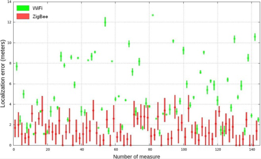
Once the system has been trained, a robot navigation test is applied to evaluate the accuracy of the fingerprinting recognition method. For every robot position, ten WiFi and ZigBee measures were collected and used separately to calculate the estimated robot's localization. Then distances between the real robot position and the one obtained with the fingerprinting method were calculated, to evaluate the effectiveness of the algorithm. In Table 2 a summary of the results for every scenario is presented, taking into account the dispersion mean (the range of each error set), the error mean and error typical deviation. In addition, Fig. 7, Fig. 8 and Fig. 9 present in a graphical manner the results of applying the WiFi and ZigBee fingerprinting method in the classroom, the corridor and the laboratory. In these figures, the vertical lines represent the range covered by the ten distance errors obtained, while the point corresponds to the most frequent result.

Comparative results of WiFi and ZigBee in classroom
Comparative results of WiFi and ZigBee in corridor

Comparative results of WiFi and ZigBee in laboratory
Localization error statistics

As can be appreciated from the results, the ZigBee fingerprinting method has greater precision than WiFi, due to the fact that ZigBee permits a greater set of training measures for a giving point, considering different power levels and frequencies, as well as fine control over the messages sent by the beacons. Moreover, the WiFi localization training set presents more unified values of every sample for a given point, while ZigBee measures vary more significantly as the robot performs movements around a specific location.
For the fine-grained localization experiments, several measures have been made in front of a door, equipped with the LED panel, as can be seen in Fig. 3, moving the robot to the measurement points (shown in Fig. 10 in grey) and comparing the visual method results with the actual position. As the results show, this method provides a localization estimation with a maximum error of 4cm, allowing the positioning of the robot in front of a point of interest with enough accuracy to perform a manipulation task in an autonomous way.
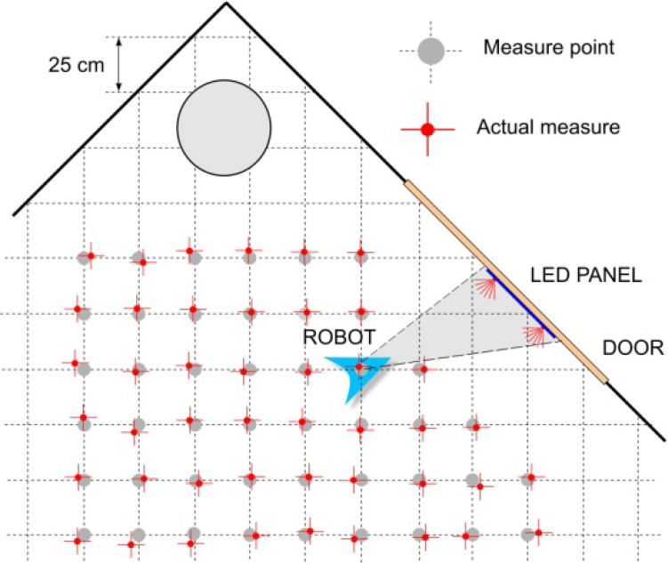
Visual Pose calibration method.
5. Conclusion and further work
This paper has presented a combined coarse and fine-grained localization method for indoor environments that may have smoke-due-to-a-fire scenario. The system provides this enhanced localization by integrating multiple sensors and using different methods depending on the required accuracy and the visibility level of the scenario. In particular, a fine-grained localization technique is used for manipulating doors and valves, which allows the identification of the exact position of an object in smoke by using high density LED panel. When navigating in an area without points of interest with good visibility, the provided map, IMU and the laser meter combined with WiFi localization can be used.
In critical areas with not enough visibility the ZigBee method provides the required precision to reach a point that brings the programmable high luminosity LED panel near and completes the positioning by visual methods.
It is necessary to consider that the proposed selected and WiFi methods require previous training for every given scenario and more hardware resources in the sensor nodes in order to perform the calculations in the pattern recognition phase.
Moreover, the article shows a proposed fingerprinting algorithm for enhancing the efficiency of localization methods in indoor environments with irregular scenarios. The method increased the performance of k-nearest neighbours recognition and produced very good results in every tested scenario. Combined with high luminosity visual localization and RFID, this may allow a robot to navigate in a smoky atmosphere and reach specific points of interest to help firemen.
Future work will focus on enhancing the integration of the described methods and tune them to get an optimum performance in both, black/hot and white/cold smoke. For the moment, the experiments have been presented using the white/cold case.
Moreover, as seen in Fig. 3, our next steps will focus on continuing the integration of the system in the rescuer platform, looking for a higher degree of autonomy in the manipulation process. Several manipulation tasks have been already proposed by the Spanish Fire Services, which would help the security and efficiency of their interventions a lot.
Footnotes
6. Acknowledgments
This work has been funded in part by the EU-VI Framework Programme under grant IST-045269- GUARDIANS of the EC Cognitive Systems initiative, the Spanish Ministry of Education and Science (MEC) under grant AP2006-00222, the Bancaja-UJI research programme under grant RETA(P1-1B209-39) and the Spanish National CICYT under grant TIN2009-14475-C04, the Spanish Ministry of Research and Innovation DPI2011-27977-C03 (TRITON project), by the European Commission's Seventh Framework Programme FP7/2007-2013 under Grant agreement 248497 (TRIDENT Project), by Foundation Caixa Castelló-Bancaixa PI.1B2011-17, and by Generalitat Valenciana ACOMP/2012/252.