
Abstract
A prototype of an automatic micropositioning system was developed. This prototype uses a shape memory alloy (SMA) actuator, a dedicated PI controller and a piece of software to command a desired motion profile for the actuator. The proposed micropositioning system is characterized by a 4 mm stroke, a 1 μm resolution and a 70 g nominal force and can be commanded directly from a personal computer and without human retroaction. The closed loop positioning resolution (1 μm) is obtained in spite of inaccurate system behaviour during its movement.
1. Introduction
Automatic micropositioning is becoming useful in a number of different applications (microscopy, medical technology, data storage, telecom, photonics, semiconductors, aerospace defence technology, micromanufacturing, etc.) [1-7]. Micropositioning is the ability to move objects with a micrometric resolution by a defined stroke [8]. A controlled microactuator is needed to carry out these tasks. Many examples of actuation technology are already available: piezoelectric, electromagnetic, shape memory alloys (SMA), electrostatic, polymeric, electroreological, SMA polymeric, chemical-mechanical, etc [9-17].
At the Brescia University Applied Mechanics Laboratory, a prototype of an automatic micropositioning system was developed. This prototype is based on a SMA actuator [18], on a dedicated PI controller and on a piece of software to command a desired motion profile for the actuator. The actuator contains six Nitinol fibres (50μm diameter and 25mm length) and, when an electric current flows through the fibres, their temperature grows (resistive effect) and they contract (SMA effect or SME). By controlling the feeding current it is possible to control the temperature or position. So a PI (Proportional and Integral) control was developed and, to close the position loop, a LVDT (Linear Variable Differential Transformer) was used. The SMA actuator can exert only a contraction force; a recovery force can be generated with a spring (variable force) or with a dummy weight (constant force).
Some recent results of studies of micropositioning systems, based on SMA technology, are given in this paper. Firstly the property of the actuation system will be described, then the control circuit will be illustrated, finally the performance of the system will be measured and a heuristic approach will be used to analyse the kinematic and the dynamic behaviour.
2. Microgripping function
A still open research issue, in the design and manufacturing of micro-gripping devices, is the study of the size effects and of the growing influence, in the downsizing process, of the superficial and adhesive forces (capillary, Van der Waals, electrostatic, …) with respect to gravity and mass related forces [19]. Indeed, at the micro-scale, the predominance of superficial phenomena, together with effects negligible at the macro-scale, calls for design criteria and solutions different from those commonly used for the manipulation of components. The release phase is often critical and failures due to sticking effects caused by adhesion forces or electrostatic jump are often reported. Therefore, methodologies and tools for the robust design of microgrippers have been developed, including the modelling of superficial interaction forces between the gripper and the component, and the component and the substrate.
Different grasping and releasing principles are present in the literature; in particular, commercial mechanical tweezers with different actuating systems (such as electrostatic actuation, hydraulic or pneumatic, piezoelectric control, SMA, and thermal actuation). Among the different technologies considered, SMA emerged as the preferred for their reduced power/weight ratio and because they need only electrical power.
3. Actuator properties
Shape memory alloys (SMA) represent a class of metallic materials with particular thermo-mechanical and electrical properties, high power density and the ability to produce comparatively large actuation strains/stresses. Their actuation properties originate from a solid-state phase transformation, which is affected by changes in temperature or stress, and strain. SMA actuators are widely used in wire or spring configurations, but upcoming applications in, e.g., medical instrumentation or microsystems also demand more complex shapes [20-23]. However, designing SMA actuators is a challenging task, due to their complex material behaviour and also electrical, thermal and mechanical aspects have to be considered simultaneously.
SMAs are intermetallic compounds able to recover, in a continuous and reversible way, a predetermined shape during a heating/cooling cycle. From a microscopic point of view, this transformation consists of a transition from a crystallographic phase stable at a low temperature, i.e. martensite, to a different crystallographic phase stable at a high temperature, namely austenite. When the SMA is deformed by an external force, instead of breaking crystallographic bonds and damaging its structure, it starts a progressive arrangement of planes which close the deformation without achieving significant atomic displacements. During this mechanism, the atoms have moved only slightly from their original positions, when, due to an imposed stimulus, atoms move to restore the previous crystal structure before the deformation and then the recovery of the macroscopic original shape.
A peculiar topic crucial in the selection of SMA is operative temperature range. All memory alloys have temperatures that characterize their internal structure. Temperatures of phase transformations for the adopted alloy are: temperature at the end of the martensitic transformation (Mf), the martensitic transformation start temperature (Ms), the austenite transformation start temperature (As), end temperature of the austenitic transformation (Af) and hysteresis. The temperature Af indicates the maximum operative temperature for SMA materials; in fact for higher temperatures no transformation phases are noted. The SMA element remains in the same position and all exceeded power is dissipated. The temperature Mf indicates the lower limit of the resting phase of the SMA element and the internal structure of the alloy is all in the martensitic phase.
The SMA actuation principles and properties are well described in [24-28].
Geometrical, mechanical, electrical and thermal characteristics should be taken into account, to properly design the system [29].
Among the geometrical properties of a nitinol fibre, diameter influences highly the actuation performance, for example: the resistance for a unit of some length, the deformation force (during the cooling), the SMA force (during the heating) and the cooling speed.
Some characteristics of the material are listed in Table 1.
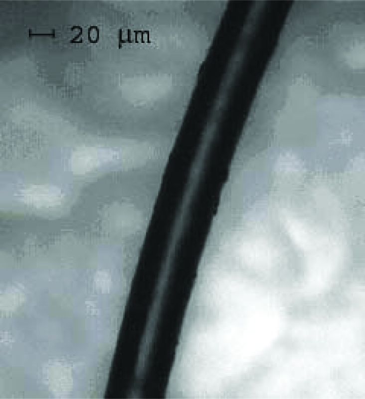
50 μm diameter NiTi SMA fibre
NiTi characteristics

The actuator, as mentioned in the introduction, is composed of six fibres that are connected in a folded geometrical form, as shown in Figure 2.
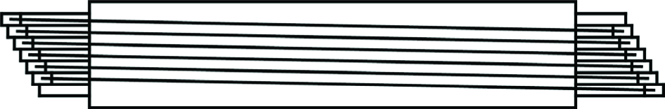
Illustration of the fibres connection.
PWM signal generation

PWM circuit
Contraction and extension speeds depend on many factors, for example: the power circuit, the environmental conditions and the material's composition. The fibre can exert the same force, regardless of the contraction and extension speed. To alter the actuator speed, many thin fibres can be used in a parallel configuration; as a matter of fact the cooling speed increases with volume reduction [30].
The conversion of electric energy into mechanical work is produced through a heating effect which occurs due to the resistance and the Joule effect. This is a low efficiency process: only 5% of the supplied energy is transformed in mechanical work. To improve the efficiency, high diameter fibre can be used, but it leads to a reduction in speed. However, the nitinol fibres have other merits, such as reduced weight/force ratio, reduced dimensions and linear movement with low tension.
The fibre life depends on its composition, its treatment and especially on the applied force and its desired recovery ratio. If the desired recovery ratio is 8%, the fibre life is about 12 cycles. If the recovery ratio is between 3% and 5% and overheating is avoided, the fibre life can be over one million cycles: usually the SMA micromotor breaks because of the mechanical parts.
The pretension force is opposed to the contraction and is used to gain the initial position during the cooling phase. The pretension force can be imposed in many ways, for example with a weight or a spring.
A constant force is always applied to the system for the direct (or regular) pretension (for example a weight) and, during the cooling, it is able to extend the fibre.
For the inverse pretension, the pretension force is proportional to the contraction (for example a spring) and it increases during heating while it decreases during cooling: thus a correct selection of the spring can extend the fibre life.
In this work the constant recovery force is set to 42.07 g, and the elastic recovery is realized with a spring that produces a force in the range 37÷77 g.
4. Actuation control
Movement can be controlled by controlling cooling and heating, because the SME is based on thermal effects. The most commonly employed method of SMA cooling is thermal conduction, but minimal air convection allows for good cooling performances. Liquids guarantee better cooling conditions than air, but they pose insulation problems: the best solution seems oil but it needs design expedients to avoid leaks. For the nitinol fibres considered in this paper, experiments show that a good actuator behaviour can be achieved with a simple air conduction cooling.
Interestingly, it has been observed that there is a decrease in the cooling time when the mechanical load increases. This happens because As and Ms increase with load increase, so the difference between environmental and fibre temperature increases.
The most employed SMA heating method is the resistive Joule effect [29].
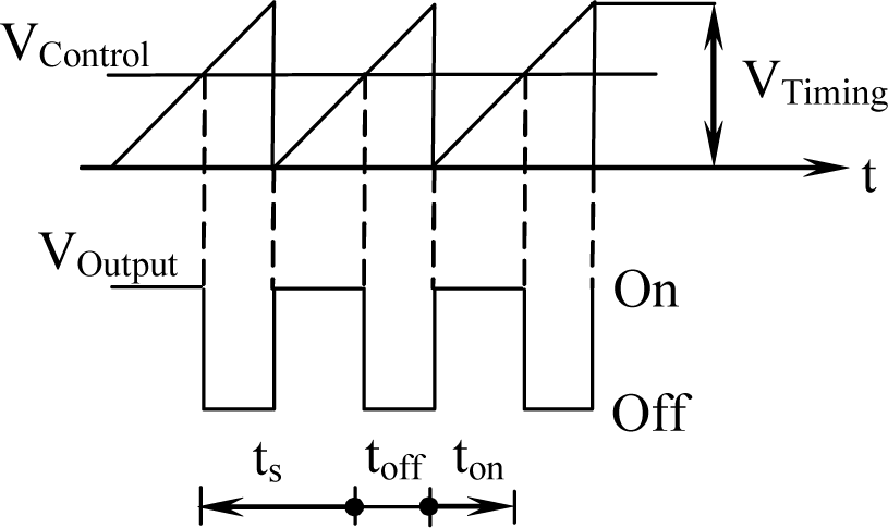
To obtain a smooth contraction movement, a PWM (Pulse Width Modulation) power circuit is used, because it allows for the homogeneous heating of a fibre section [31].
A PWM circuit generates a square wave VOutput with a constant frequency, comparing a control signal VControl and a periodic wave VTimng. The duty-cycle is defined as (1), where: ton is a half of the square root period and ts is the low VOutput tension time (Figure 3).

The actuator current is controlled by the duty-cycle. The frequency of the VOutput wave should be greater than 100 Hz to obtain a smooth movement; i.e. the harmonic content of the actuator movement should be much less than the frequency of VOutput. The PWM circuit can be realized with a simple Timer 555 (Figure 4).
A duty-cycle change involves a change of the actuator input tension and it defines the relation for the regulation of the actuator speed with the system shown in Figure 5.
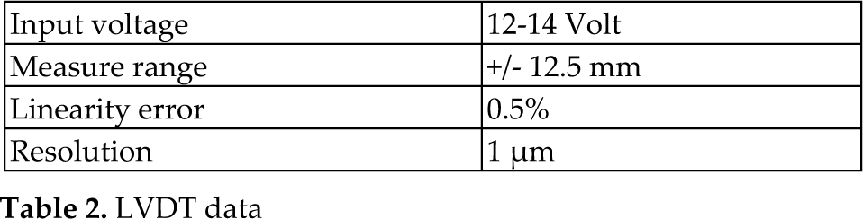
To determine the level of fibre contraction, a LVDT sensor is used (Table 2); this measurement is then used to control the actuator position.
LVDT data
The chosen controller is a PI (proportional, integral) and it is made with a TL074. Controlling SMA has been of increasing interest in the last years and some methods can be found in the literature [32-33]; as shown in [34-35], the problem of controlling the position of a SMA fibre can be solved using a proportional function and an integral function to take into account the history of the system, whereas a derivative function should be avoided, because the actuator is relatively slow. In [34], the stability of a PI actuator is clearly demonstrated, thus this simple solution seems the most interesting for the controlling the position of the actuator.
To command the actuation motion as desired, custom software was developed. It implements different types of motion profiles [36-37]: trigonometric splines, polynomial splines and a polynomial series. The motion profile design is performed in the acceleration diagram, whereas speed and position are obtained by integrations [38-40].
5. Actuator performances
Having now described the actuator principles and the method of control, the results of testing their performance are given.
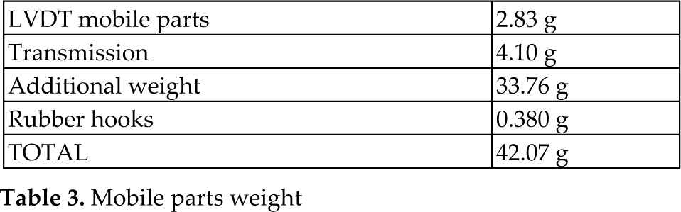
The first experimental setup is composed of a SMA actuator in a vertical configuration (Figure 7), so the weight of the movement parts can be used as a pretension constant force and its value is given by the data in Table 3.

Closed loop scheme, where C is the controller made of a TL074, P is the PWM generator made of two TLC555, A is the actuator, LVDT is the sensor

Control circuit
Mobile parts weight
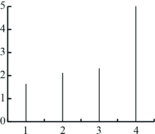
The obtained minimal cycle periods per stroke are shown in Figure 9. The positioning resolution is 1 μm.
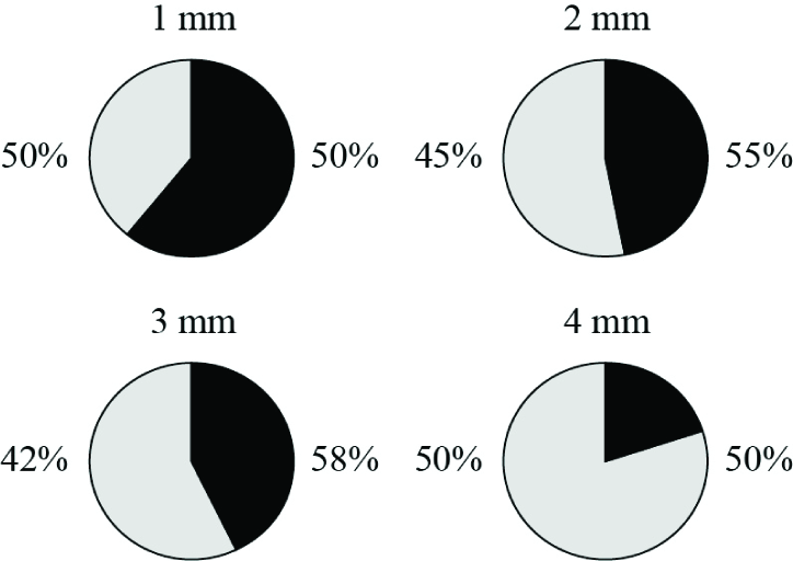
The percentage of contraction and extension cycle time is shown in Figure 10 and there is a relation between contraction time and stroke: when the stroke is less than the maximum available stroke and when the stroke is not too low, the contraction time can be reduced.
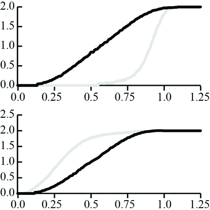
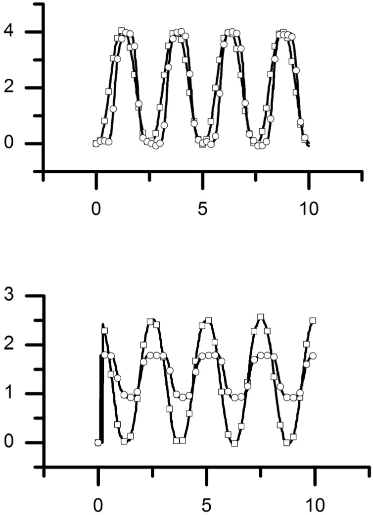
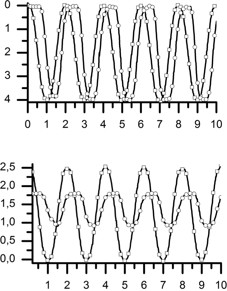
An example of the difference between an experimental and a commanded motion is shown in Figure 11, where one can observe a high error during the movement and a low error at the end of the movement.
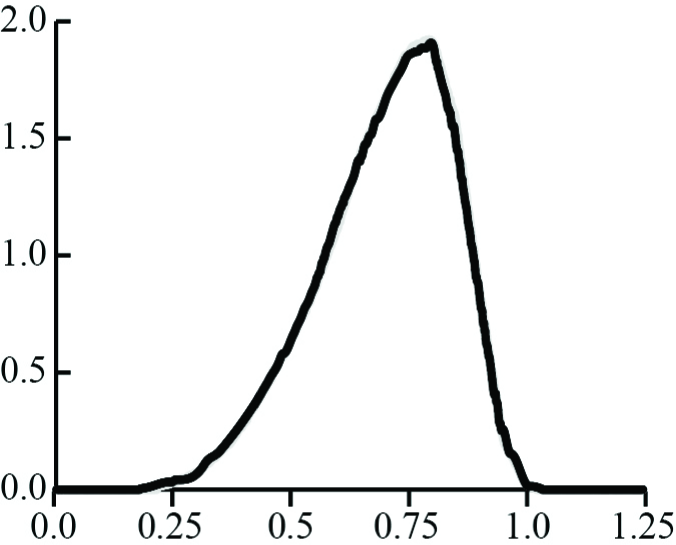
The average square error (Figure 12) is very high during the movement and it reaches its maximum at the middle of the contraction (or extension) time. At the end of the contraction and at the end of the extension, the position close loop allows a drastic error reduction.
The second considered setup is a horizontal position and it uses an elastic pretension force produced by two parallel springs (Figure 8). These springs have an unloaded length of 12.7 mm, a pretension of 11 g and a rigidity of 5 g/mm.

Solid Model of the vertical experimental setup, where A is the position of the actuator and S is the position of the sensor (LVDT)

Solid Model of the horizontal experimental setup, where A is the position of the actuator, S is the position of the sensor (LVDT) and SS is the position of the springs

Minimal actuation period (contraction with a following extension) [s] versus stroke [mm]

Contraction (grey) and extension (black) time percentage for different strokes

Measured (grey) and commanded (black) displacement [mm] versus time [s]; the first diagram shows the contraction movement and the second diagram shows the extension movement
The obtained results are showed in Figure 13-16, where we can observe that:
the minimal actuation time (contraction with a following extension) is proportionally related to the stroke;
the contraction time is strictly proportional to the stroke, whereas the extension time is inversely proportional to the stroke;
during the movement accuracy is low, because we do not properly take the return force into account, but the positioning accuracy is really high (at the end of the movement);
during the first part of the cycle, there is a delay in the measured movement with respect to the commanded one; then the actuator is not able to react quickly to the passive return action of the spring and the spring anticipates the commanded motion.
the maximum square error is at the middle of the stroke.
6. Experimental setting
In the following section, we show some experimental observations achieved with a horizontal setup that can also be applied to the vertical condition.
The SME is based on a thermal effect, so, if a SMA fibre achieves many fast movement cycles repeatedly, a thermal drift (Figure 17) can be observed and the maximum fibre contraction increases, but, because the described SMA actuator will be used in a robotic system, only the first actuation cycle (contraction with a following extension) is usually considered.

Square error [mm2] versus time [s] for the first contraction (grey) and for the second contraction (black)
Minimal actuation period (contraction with a following extension) [s] versus stroke [mm]
Contraction (grey) and extension (black) time percentage for different strokes
Measured (grey) and commanded (black) displacement [mm] versus time [s]; the first diagram shows the contraction movement and the second diagram shows the extension movement
Square error [mm2] versus time [s] for the first contraction (grey) and for the second contraction (black)

Real displacement (black) and the commanded displacement (grey) [mm] versus time [s]
The power circuit is activated manually after the motion command generation, so a delay is measured by the LVDT. The power circuit cannot be activated before the motion command, because otherwise saturation occurs in the fibre and it leads to overheating. This is a preliminary prototype and further developments are planned for the next version.
During all the trials, the starting set point signal is higher than the LVDT signal, because the integrator should be interdicted during the starting phase to avoid controller saturation. By increasing the set point, the motor movement becomes more rapid; but if the set point is too high, the controller is too saturated and a delay appears.
This phenomenon is associated with integral windup. Integral windup is an anomalous non-linear overshoot that can be present in integral controllers (i.e. PI or PID). The onset of windup occurs when the actuation command is constrained by maximal and minimal values (i.e. saturations). The setting of a step input error induces the integral action of the controller, which increases the output. When the output value can also saturate the actuation command with an increasing integral output, the actuation command remains constant. If the system is stable, after some time, the error becomes negligible and the integrator starts discharging and, until the output is higher than the saturation, the actuation command remains constant. This phenomenon produces a non-linear overshoot. Different techniques are known in the literature to reduce windup [41]: in this work, this phenomenon is not explored more deeply and must be dealt with in future works.
Another analogous disagreeable effect occurs when a sinusoidal motion is commanded and a deformation is created at the start and at end of the contraction, where a pause of the movement is observed. When many following cycle are commanded, this deformation increases, because of a thermal drift effect. The actuator shows a horizontal interval after the contraction and after the extension. The actuator remains in the extreme positions for 1.5 s, thus the period was limited to a downward motion profile of 1.25 s and with a similar upward motion profile of 1.25 s (Figure 18) to reduce the saturation. The set point voltage is within the interval 0÷2.5 V and the output needs 0.472 s to reach the regimen.
The displacement diagram of the actuator confirms a reduction of the saturation especially during the contraction (Figure 19). By increasing the number of cycles, the saturation after the contraction increases due to thermal effects; in fact the temperature of the Nitinol fibres increases with the number of contractions. This motion profile cannot be accelerated to reduce the saturation; in fact, with a reduced period, as shown in Figure 20 with an upward time and a downward time of 1 s and with a voltage in the interval of 0÷2.5 V, the actuator cannot reach the initial position after the second cycle and needs two cycles to reach the final position (at the end of the 4 mm stroke).
Commanded motion profile (squares) and realized displacement (circles) [mm] versus time [s] (up), input (squares) and output (circles) voltages [V] versus time [s] (down) for a period of 2.5 s.

Zoom of the displacement [mm] versus time [s] of the actuator at the starting point (up) and at the end of the stroke (down)
To reduce this deformation it is possible to increase the cycle period. When a constant pretension force is used, a cycle frequency increment can be achieved with an asymmetric commanded motion, where the contraction and the extension use a different amount of the cycle period, because the real fibres need more time for the extension then for the contraction.
With a motion profile in contraction for 0.75 s and motion profile in extension expanded to 1.5 s, a voltage in the interval 0÷2.5 V and a turn-on time of the LVDT sensor of 0.129 s, the actuator can move cyclically within the limits of the stroke (Figure 21). For a thermal drift, the actuator is able to increase its contraction speed with the number of cycles; in fact an increase of the temperature in the Nitinol fibres reduces the contraction time. Thus the set point voltage necessary for the starting of the movement decreases with the number of cycles. Thus, the saturation in the off position is also reduced with the number of cycles, because the actuator response improves with the same input voltage. On the contrary, the saturation in the downward part of the stroke grows with the same input voltage because the increased temperature increases the cooling time. The motion profile in Figure 21 is realized with a frequency of 0.444 Hz and exhibits a reasonable behaviour reaching the extreme limits of the stroke 0÷4 mm.
If the commanded stroke is less than the maximum stroke, and the pretension force is constant, a gradual increase of the maximum contraction is observed, because the thermal effect causes a general thermal increase and the fibre needs less time to achieve a contraction. To avoid this problem a pause between two commanded cycles can be used, so the fibre can relax. Another approach to reduce, but not to avoid, the increase in contraction is to use asymmetric commanded motion.
An elastic pretension force reduces the contraction increase and the contraction pause, but, when the cycle frequency is too high, the maximum contraction decreases, because of the mechanical load. If an elastic pretension force is used, usually, the contraction time is less than the extension time.
Commanded motion profile (squares) and realized displacement (circles) [mm] versus time [s] (up), input (squares) and output (circles) voltages [V] versus time [s] (down) for a period of 2 s.

Zoom of the displacement [mm] versus time [s] of the actuator at the starting point (up) and at the end of the stroke (down)

Zoom of the displacement [mm] versus time [s] of the actuator at the starting point (up) and at the end of the stroke (down)
Figure 22 shows an actuator contraction of 4 mm in the first and second cycles and a contraction of 3.994 mm in the sequent cycle with a passive recovery spring. The reduction of the extension period (from 2.5 s to 1 s), with respect to the conditions of symmetric motion profiles, does not allow for an increase in the proper stroke. In fact measurements show a stroke of 3.988 mm, 3.960 mm and 3.955 mm, respectively, at the end of the first, second and third extension. Unlike the passive constant force with a weight, the contraction time is less than the extension time, due to the important force variation from 37g to 77g. The increment of the contraction time produces a saturation of the actuator in the downward stroke.
7. Conclusion and future developments
An experimental micropositioning system based on a SMA actuator was described. The design choices, the setting of the closed loop actuator behaviour and its performances were pointed out. The results are highly satisfactory in terms of positioning resolution and design simplicity. The difference between real and commanded motion can be reduced, commanding a more executable motion. To achieve this aim, software, implementing a realistic electro-thermo-dynamic model, will be compiled. The kinetostatic optimization will be improved with a suitable automatic optimization algorithm.
Footnotes
8. Acknowledgments
This work was supported by the EU Project “Integ-Micro” NMP-2007-3.5-2. The authors wish to thank the European Commission and all the partners of the consortium. We are grateful to the editor and to anonymous reviewers for their kind contributions.