
Abstract
The RF band pass filters are important for wireless communication applications. They can be realized using Thin Film Bulk Acoustic Resonator (TFBAR).TFBAR is designed using Aluminium Nitride (AlN) and electrodes of piezoelectric material are made with Platinum (Pt). Various modelling techniques has been used for realizing three layered TFBAR structure. Modified Butter worth-van Dyke model (MBVD) is one used for numerical simulation of AlN film and thin electrodes. The result shows that Lm, Cm, Rm and Co model is perfectly applicable for predicting the response of TFBAR. The proposed design is realized by connecting three series and two shunt FBARs in ladder configuration. In the present work, the filter has been designed for a bandwidth of 270 MHz at −3 dB. The minimum insertion loss of −0.9 dB and return loss of –25 dB are obtained for VSWR ≤ 2 at resonance frequency.
1. Introduction
Various break throughs in integration process enable the miniaturization of RF transceiver systems. Because RF front–end handled transceiver systems requires number of IF and RF band pass filters for band selection. Up to 2001, PCS duplexers are made out of Surface Acoustic Wave (SAW) filters and ceramic filter as frequency selective devices. However, SAW and ceramic filters quit large in size and power handling for stringent power requirements. The miniaturization and integration on- chip for RF band pass filter are upcoming difficult issues in designing. In 2001, researchers have made their efforts on Film Bulk Acoustic Resonator (FBAR) in improving the quality of material and making advancements in technological process. FBAR technology in the form of PCS duplexers showed up in mobile phones. Miniaturization has increased high transmission rate, high power handling and high quality factor, which leads to efficient designing of circuit and component [1]. These factors have contributed for the improvement of FBAR technology in developing various filters in wireless communication [2]–[3]. The optimization has become an important part in design process of FBAR filter configurations, in which ladder type is one of the straight forward method in designing resonator. Using Modified Butterworth-Van Dyke (MBVD) model with lumped elements, we obtain the resonant frequency for one-dimensional mode. The obtained resonant frequency is based on all parameters and constants of piezo electric material. In this paper we implemented the equivalent circuit model, which validate the three layered structure numerically and investigate response of resonator.
Here, a systematic methodology for designing a ladder type filter has been proposed. In ladder type topology resonator sizes are fixed and number of resonators can be increased to achieve out-of-band rejections. The procedure is based on the collection of closed form of expressions for optimization. There are two types of topologies for comprising FBAR filter like ladder type and lattice type for analysing the characteristics. The ladder type topology is used to observe performance characteristics of designing FBAR filter. Using commercial softwares like Agilent ADS, Ansoft designer, the FBAR resonators can be used to design RF filters conventionally.
2. Modeling of Single TFBAR
Thin film Bulk acoustic resonator (TFBAR) is a promising technology to overcome the difficulties of miniaturized filter and provide compatibility for current IC technology. FBAR is composed of thin film piezoelectric materials such as Lead-Zirconium-titanate (PZT), Zinc oxide (ZnO), Aluminium nitride (AlN). In early day Zinc Oxide (ZnO), is the only material for the researchers, but the deposition on semiconductor is difficult by nature. The electromechanical and piezoelectric properties, and the CMOS compatibility, have made AlN the preferred material for FBAR implementation. Aluminium nitride (AlN) is another choice of with high acoustic velocity and less acoustic loss allows the typical device to resonate in the gigahertz range. The main piezoelectric properties of AlN and ZnO are listed in Table I.
Electro mechanical properties of piezoelectric materials

Geometry of FBAR structure shows the piezoelectric material sandwiched between top and bottom electrodes as shown in Fig. 1. The area and thickness of a resonator can be controlled to improve the bandwidth characteristics of filter [4].
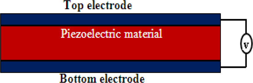
The schematic of FBAR structure.
For analysing FBAR, it is necessary to have reasonable models, where Mason equivalent circuit model is accurate and valid for one-dimensional multilayered resonators and transducers. The parameters involved using Masons model are distributed values rather than constants and it is time consuming to analyse FBAR structure. Butterworth-Van Dyke (BVD) equivalent circuit model is a lumped element model, which is valid near resonance frequencies of one-dimensional mode. These models are based on the parameter constants of piezo electric material and the designed resonator.
The modified Butterworth-Van-Dyke (MBVD) model allows obtaining more realistic representation of FBARs and acoustic resonators. The MBVD accounts for dielectric and ohmic losses in the piezoelectric material and the transmission line by using resistances Ro and Rs. In MBVD equivalent model, the thickness of electrode and piezo- layer are considered as whole piezoelectric structure, which is used to simulate the resonator behaviors. The MBVD circuit is as shown in Fig. 2. This results from adding R0 and Rs to the BVD circuit. In the parallel-plate capacitance arm, R0 is serially added to C0, whereas the transmission lines connecting the resonator are split in two components of resistance RS/2, each one corresponding to the bottom and top electrode line losses.

MBVD equivalent circuit of single resonator.
In this paper, we use conventional ladder type filter with different size resonators in series and shunt which are analysed by using 3/2 ladder topology to achieve frequency response of FBAR filter [5].
3. Topology for Ladder Type FBAR Filter
The transmission response of a resonator determines the Impedance characteristics of FBAR filter. Electrical performances such as low insertion loss, return loss and VSWR are the major design goals a resonator. The proposed FBAR filters are designed by using 3/2 ladder topology as shown in Fig. 3. The polarization is in phase with an applied electrical signal for series resonator and it is 180 degree out of phase for shunt resonator.

The topology of 3/2 ladder.
Modified Butterworth-Van Dyke (MBVD) is composed of lumped elements which are useful for extracting functional parameter of each resonator. Taking the parameters of AlN and group of electrode material with their thickness can substituting these data in below equation, one can find out impedance distribution [6]. The following parameters are used for designing equivalent circuit for different resonators based on physical dimensions.


Where C0 represent physical plate capacitance of FBAR, Rs represents the physical resistance of the top and bottom electrodes. Lm, Cm and Rm represent the motional resonance voltage of Piezo electric material, ε is permittivity of piezoelectric material, A is area of resonator, d is thickness of resonator. The series and parallel resonance frequencies can be deduced from data of input impedance fp and fs are resonance and anti resonance of resonator [7].
The unit size of designed resonator is 120×110×1μm3 and the Equivalent circuit parameters of proposed structure are listed in Table II.
MBVD equivalent circuit parameters of proposed structure.

4. Results and Discussion
As mentioned in the previous section the resonators are connected in series and shunt ladder configuration. All FBARs are acting as capacitors in the frequency region far from the pass band. Thus, each size of the series and shunt FBAR device needs to be optimized for realizing band pass filters with low insertion loss and high attenuation characteristics. The performance of characteristics of FBAR filters purely dependents on size of each resonator. Thus the size of each resonator should be optimized for developing a FBAR filter with good performance. The quality factor depends on the acoustic loss, ohmic resistance of electrodes and acoustic radiation into the surrounding area of the device.
The return loss and insertion loss of 3/2 ladder configuration as shown in Fig. 4 and Fig. 5. The designed FBAR band pass filter gives a return loss of −25 dB and an insertion loss of −0.9 dB with a bandwidth of 270 MHz at −3 dB and voltage standing wave ratio is observed (VSWR) ≤ 2 for designed frequency as shown in Fig. 6.

Simulated return loss characteristics of 3/2 FBAR filter.

Simulated insertion loss characteristics of 3/2 FBAR filter.

VSWR plot of designed FBAR filter.
The FBAR filter models are analysed based on ladder type MBVD equivalent circuit models. S-parameters of 2-port network are best suited for studying frequency response of FBAR filter. The designed FBAR filters are used for several L band applications.
5. Conclusion
In this study highly miniaturized band pass filter based on the TFBAR have been designed and analysed. The 3/2 Ladder type topology is proposed for filter design. The size dependency has also been investigated based on the performance characteristics of resonator and the filter. The designed FBAR filter is an attractive application in modern wireless communication. The minimum insertion loss, return loss are obtained with band width 270 MHz and VSWR ≤ 2 for designed frequency. The demonstrated TFBAR device is used for developing integrated and miniaturized filter banks, RF-front end modules and RF transceivers due to their compatible fabrication sequence with CMOS for RF IC circuitry. The above results are used for few L band applications in designing of FBAR duplexers.
Footnotes
6. Acknowledgments
The authors would like to gratefully acknowledge the DR. A.M. Varaprasad Scientist ‘F’ DRDO, Prof.K. Jagadeesh babu and Prof. J. Lakshmi Narayana of SACET for their support.