
Abstract
We discuss the development of a mini-quadrotor system and coaxial quadrotor system for indoor and outdoor applications. The attitude control system consists of a stability augmentation system and a modern control approach. To perform an experimental flight test, a PID controller is used to validate our aerodynamic modelling and basic electronics hardware is developed in a simple configuration. We use a low-cost 100 Hz AHRS for inertial sensing, infrared (IR) sensors for horizontal ranging, an ultrasonic sensor for ground ranging and an AVR microcontroller for the flight control computer. A ground control system is developed for the monitoring and gathering of flight data. Based on the modelling and simulation data of the mini-quadrotor system, a flight test is performed and automatic hovering ability is implemented. A collision detection system is one of the important parts of an indoor and outdoor flight test. To overcome the payload limitation of the mini-quadrotor system, we design a coaxial quadrotor system and we use a Kinect sensor as the collision detect sensor. Kinect sensors give 3D depth information and the collision detection system uses that information.
1. Introduction
Recently, quadrotor system development has become more popular in academic research. Several techniques and methods for modelling, simulation and control design have been developed [1–5]. A quadrotor's structure and dynamics are simpler than conventional helicopters, thus, a quadrotor has less control complexity [6]. However, since the quadrotor is an unstable system, the first issue in the design of an autonomous system is the implementation of attitude stabilization control.
The quadrotor has four powerful rotors running at a very high rotational speed. Key issues include attitude sensing quality and a reliable frame structure. On the vehicle, there are high magnetic fields from brushless direct current (DC) motors and very high vibration from the propulsion system. An adequate sensor requires a correct measurement value under such conditions [7][8]. Since a small size quadrotor system has a payload limitation, the challenge is to find a light-weight inertial measurement unit (IMU) with good performance. A control approach will take that role and give an advantage in satisfying the stabilization with an available configuration [9]. Based on the same process, a coaxial quadrotor is also developed. Collision avoidance is very important for any type of aerial vehicle. Although Kinect sensors have been developed as a gaming device, they have good accuracy of distance information – 95% accuracy based on the test. The weight of a Kinect sensor is 550g and coaxial quadrotor payload is about 1kg, so the coaxial quadrotor can fly with the Kinect sensor. Depth information from the Kinect sensor is used to measure the distance between the coaxial quadrotor and collision. Then, the ground control system takes the distance information from coaxial quadrotor and displays the warning message. In this paper, we show the modelling and control of a coaxial quadrotor and collision avoidance system using a Kinect sensor.
2. Quadrotor
A basic quadrotor system consists of air frame, propulsion, flight control computer (FCC) and ground control system (GCS) components. The FCC handles the speed of motors and the GCS receives the data from quadrotor and gives a command to it. This section gives a broad overview of the quadrotor system.
2.1 Configuration
The proposed flight control system is driven by an NXP LPC1768 with an ARM-7 MCU that operates using a system clock at 100 MHz. The control system consists of a data acquisition system for acquiring six degrees of freedom (DOF) sensor data from an AHRS and a flight controller that implements the control algorithm. The control system drives four channels for four electronic speed controllers using I2C communication. We feel confident of the fast response propulsion system here rather than using a PWM speed controller.
In the configuration shown in Figure 1, the quadrotor system is controlled autonomously by a ground control system using a 900 MHz radio frequency (RF) modem and a radio control (RC) pilot can take over manually. The flight control system (FCS) also has the ability to auto-lock the command input in a standby mode as a safety feature, then wait to receive a special command input as a password to unlock the system.

Block diagram of quadrotor hardware
A 1200 mAh 11.1 V Li-Po battery was used to drive all the electronics and the four DC brushless motors. A battery checker system in the FCC can prevent an uncontrolled situation when the power goes down or is depleted during the flight; thus, the quadrotor can make a safe landing Figure 2 shows the Konkuk University (KU) quadrotor with a frame protector that can reduce heavy damage from a crash. Because of its light weight and high elasticity, a carbon rod was used for frame protection. As shown in Table 1, the total weight is 0.582 kg without frame protection. Figure 3 shows the proposed ground control system (GCS). A laptop computer was used for the GCS, which was based on the C# programming language. The GCS consists of a manual mode and an automatic mode. The manual mode is for experiments and scouting. The automatic mode is for autonomous flight based on a GPS signal.
Details of quadrotor weight

KU quadrotor vehicle with frame protector

Ground control system for KU quadrotor vehicle
2.2 Modelling
We introduce our quadrotor model based on the Newton-Euler concept to describe the equation of motion of a 6 DOF rigid-body, as shown in Figure 4. The main motion factor is the speed of the four rotors (Ω1, Ω2, Ω3 and Ω4, rad/s). The motion can be varied by changing each rotor's speed [9].

Dynamics of the quadrotor
With regard to Fig. 4, Ω1 is the speed of the front propeller, Ω2 is the speed of the right propeller, Ω3 is the speed of the rear propeller and Ω4 is the speed of the left propeller. The overall propeller speed (Ω, rad/s) generation is represented by the following equation [11]:

The vector of movement is represented as Equation (2):

where l (m) is the distance between the centre of the quadrotor and the centre of each propeller. b (N s2) is the coefficient of thrust and d (N m s2) is the coefficient of drag that contributes to the aerodynamics around the propeller.
The thrust of each rotor is generated by the rotational speed of the motors and by the aerodynamics of the propeller blade. Collectively increasing each rotor's speed using all motors may increase lift and vertical dynamics translation (z̈).
Pitching motion (q, θ) can be driven by varying Ω1 and Ω3 oppositely. The same method is applicable for horizontal translation (ẍ). The rolling motion (p, φ) can be driven by varying oppositely Ω2 and Ω4. This is also applicable to the horizontal translation (ÿ). Yawing motion (r, Ψ) can be produced by making all the counter-clockwise rotors greater than the clockwise. Two rotors (Ω1 and Ω3) rotate clockwise, while the other two rotors (Ω2 and Ω4) rotate counter-clockwise. With an assumption that each thrust values is equal, the yawing motion can be assumed to be stable, even though the dynamics of the quadrotor produce an unstable system.
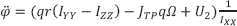
The quadrotor motion is described by Equation (3)
where g (m/s2) is the gravity force, m (kg) is the overall quadrotor mass and Iii is moment of inertia of each axes obtained by estimation. JTP (N m s2) is the total rotational moment of inertia. In this project, this value is ignored or assumed to be zero due to minor influence on modelling [10].
We built the model using MATLAB/Simulink® software for simulation and as a basic reference for designing the control system. As shown in Figure 5, the model was divided into several blocks. Each block required validation according to the real system. We used a rotor transfer function from a previous study with an additional response time delay due to the communication exchange between the microcontroller and speed controller [10].
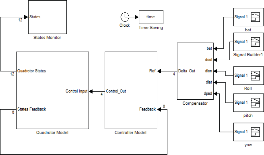
Quadrotor model with inner loop control
2.3 Control System
For validation purposes, we implemented a proportional-derivative controller on the quadrotor to acquire flight data to compare with the simulation [8], [9].
Roll rate(p), roll angel(φ), pitch rate(q), pitch angle(θ), yaw rate(r) and yaw angle(Ψ) are used for state variables, and control inputs consist of four control parameters which are vertical control (δ col ), longitudinal cyclic (δ long ), lateral cyclic (δlat) and directional control (δ ped ). The input sensitivity is handled by Kδcol, Kδlong, Kδlat and Kδped.
The system inputs are as below.


The first control algorithm that we implemented is shown in Figure 6. The system consisted of a damper and attitude holding for roll, pitch and yaw. The control linkage was represented by the rotor dynamics of the devices that linked the control output to the dynamics of the vehicle in certain constants [10].

Control system as the inner loop
The base controller used a reference of zero, also known as the equilibrium, due to the hovering mode of the quadrotor. Experiments were conducted to determine the control parameters one-by-one for the all members of the single-input single-output (SISO) from the inner loop to the outer loop.
First, we implemented the proportional control described by Equation (8) as a damper, using rate gyro sensor data to stabilize the angular rate in each axis:

The proportional control was implemented for each angular rate (p, q, r), to investigate the manoeuvrability of the vehicle. The low damping ratio maintains the vehicle in a marginally stable region. However, too high a damping ratio could cause sluggish behaviour. An appropriate trade-off through systematic design process is desirable.
In the next step, we implemented the PD controller for attitude holding described by Equation (9), for the roll, pitch and yaw.

By taking the sum of Equation (8) and (9), we derived the following total inner-loop control equation:

where CD (s) represents the rate damping controller, gr represents the rate gyro outputs, (p, q and r, respectively), kp is the proportional gain for rate damping CAH (s) is the attitude holding controller, #θ ref (s) is the input reference, θ(s)is is the current position, kp + kd s is the PD gain for attitude holding and C(s) is the total control output.
The initial tuning of the gains was guided by the Linear Quadratic Regulation controller design. LQR is the most practical application of optimal control theory concerned with a linear dynamic system with a quadratic cost function. Before implementation of the LQR controller in the simulation, the controllability check of the state-space model is considered. The control law is then constructed by minimization of the following cost function [12][13].

For the continuous-time linear system described as

the state feedback law is expressed as

where K is given by

By minimization of cost function, the state vector x(t) is regulated as close as possible to the origin without an excessive expenditure of control effort. P is found by solving the continuous time Riccati differential equation [10][13].

where A and B matrices were obtained from system identification as follows:

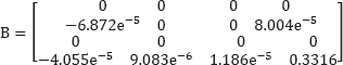

The gain matrix can then be calculated from Eq. (14)
Figure 7 shows our simulation results. The roll and pitch response was slower than that of the yaw, thus, we conclude that the roll and pitch attitude was sluggish, and deviated slightly from the zero point (this is known as steady state error)

Quadrotor model with LQ controller under simulation
2.4 Flight Test
Figure 8 shows the flight test instructions. The RC controller was connected to the GCS through a USB port. The RC controller sent the signal to the GCS, and the control signal was transferred to KU quadrotor.

GCS, RC controller and KU quadrotor for flight test
The all gain conditions are taken from experimental direct tuning on the test bed and satisfied as “able to fly” performance, as shown in Figure 9. We validated the control model based on the flight data. As shown in Fig. 9, our model includes feedback control as a stability augmentation system that used the same gain as the control model.

Inner loop controller of roll, pitch and yaw angle stabilization in a real system
The pilot adjusted the throttle input due to the voltage drop in order to maintain the vehicle in a hovering flight state during the flight test. When the battery power decreases after a number of flights, the throttle input should be increased to generate the same thrust. We implemented a compensator in the simulation to consider a variable value from the joystick of the radio control that was recorded in the flight data. The compensator adjusted the throttle coefficient factor due to battery voltage drop during the flight.
Our outdoor flight test was successful. Figure 10 shows the outdoor flight test of the KU quadrotor vehicle. The flight time was about 10 min without frame protection.

KU quadrotor vehicle outdoor flight test
3. Coaxial Quadrotor
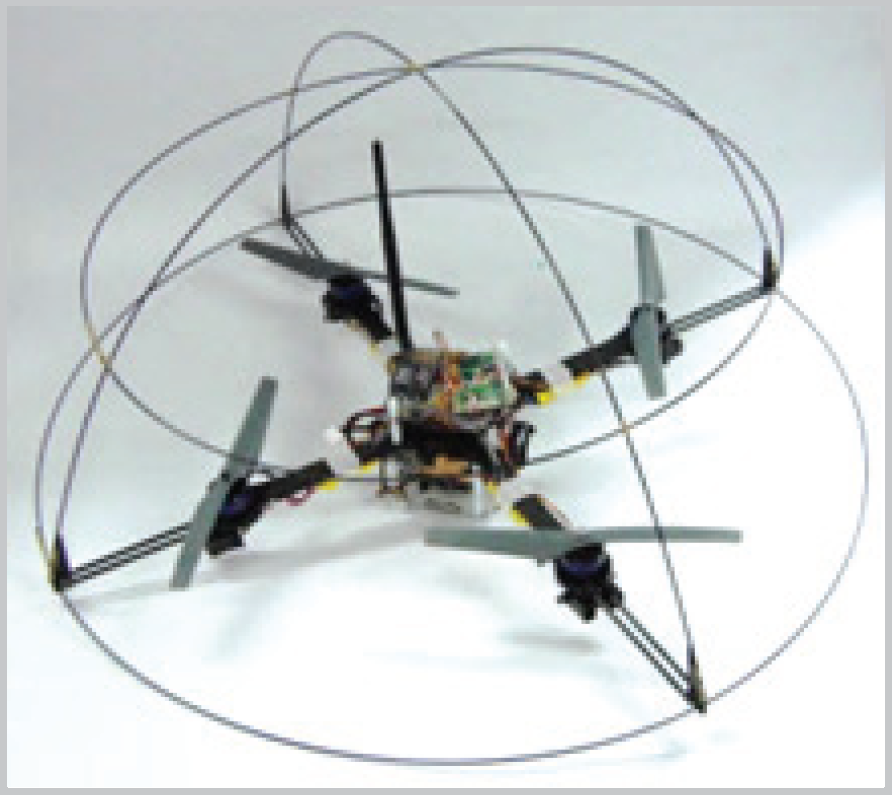
Based on the quadrotor system, it is not difficult to make a coaxial quadrotor system which has eight propulsion rotors. It has a similar structure to regular quadrotor systems, but it can fly with heavier weight mission equipment rather than the regular quadrotor. Thus, it is useful to apply various sensors. In other words, the coaxial quadrotor can adapt to various missions.
3.1 Configuration
This coaxial quadrotor is developed as an indoor collision detection system. We will mention the collision detection system in section 4. In order to control attitude, the flight control system (FCS) consists of an embedded board with ARM-7 MCU, AHRS and an electronic speed controller (ESC). Another embedded board with a Kinect sensor is needed for collision avoidance. Then, a GCS is necessary to gather the attitude and distance information from the coaxial quadrotor to the obstacle.
Figure 11 shows the main system flow chart of the coaxial quadrotor for collision avoidance. GCS receives video images from the wireless camera, distance information from the Kinect sensor and AHRS data.

Main system flow chart of the coaxial quadrotor
Figure 12 shows the flight control system of the coaxial quadrotor for collision avoidance. The Kinect sensor connects the Gumstix by USB and the distance information from collision to the coaxial quadrotor is sent by WiFi communication.

Flight control system of the coaxial quadrotor
Figure 13 shows the coaxial quadrotor with a Kinect sensor and Table 2 shows the component weight and the total weight of the coaxial quadrotor.
Weight details of the coaxial quadrotor

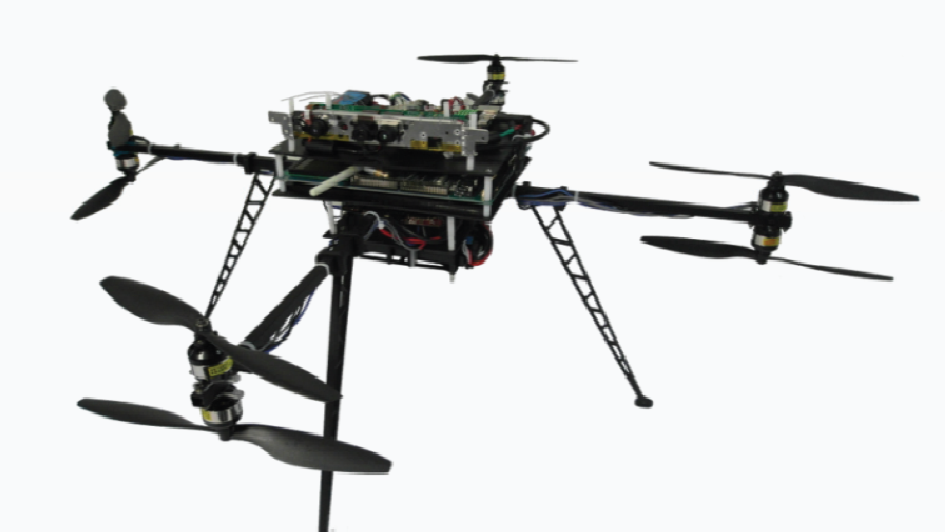
Coaxial quadrotor with a Kinect sensor
3.2 Modelling
Because of the same Newton-Euler concept, the modelling process is similar to that for a quadrotor system. Nevertheless, some parts of the modelling are different.
With regard to Fig. 14, the overall propeller speed (Ω, rad/s) generation is represented by the following equation [8]:

Dynamics of coaxial quadrotor
The vector of movement is represented as the equation below:

The vector of movement is represented as the equations below:


l(m) is the distance between the centre of the coaxial quadrotor and the centre of each propeller, b (N s2) is the coefficient of thrust and d (N m s2) is the coefficient of drag that contributes to the aerodynamics around the propeller. The thrust of each rotor is generated by the aerodynamics of the propeller blade that rotates.
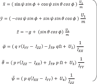
The translation of movement is represented in the following equations:


The rotational movement is represented as follows:


where g (m/s2) is the gravity force, m (kg) is the overall mass of coaxial quadrotor and Iii is moment of inertia of each axes obtained by estimation. JTP (N m s2) is the total rotational moment of inertia. In this project, this value is ignored or assumed to be zero due to minor influence on modelling [10].
3.3 Control System
Based on the Linux OS, the same control loop as the quadrotor control system is used for the coaxial quadrotor.
3.4 Flight Test
Figure 15 shows the indoor flight test of the coaxial quadrotor system. Although it flew, it was not stable. So, we need more flight tests for fine tuning.

Indoor flight test of the coaxial quadrotor system
4. Collision detection system
An IR sensor is used for the simple collision detection system based on AVR FCC, but an additional embedded system is needed for the collision detection system using the Kinect sensor. This is because although the data of the IR sensor is simple and requires low computing power, the data of the Kinect sensor is big and complex, so more computing power is required.
4.1 Collision System with IR sensor
The collision detection system with the IR sensor consists of an infrared sensor and a PID controller. Although it is a simple system, the response is very fast. Figure 16 shows the indoor flight test with the 1D collision detection system. If the quadrotor detects an obstacle, the FCC handles the motors and makes it fly back.

Indoor flight test of the collision detection system using the IR sensor
4.2 Collision system using the Kinect sensor
Figure 17 shows the collision detection system using the Kinect sensor flow chart. That system consists of a Gumstix and a Kinect sensor. The Libfreenect library is installed at the Gumstix embedded board to obtain the distance information and RGB images from the Kinect sensor via the USB port [14]. Then the image data is sent to the GCS over WiFi network under TCP/IP protocol.
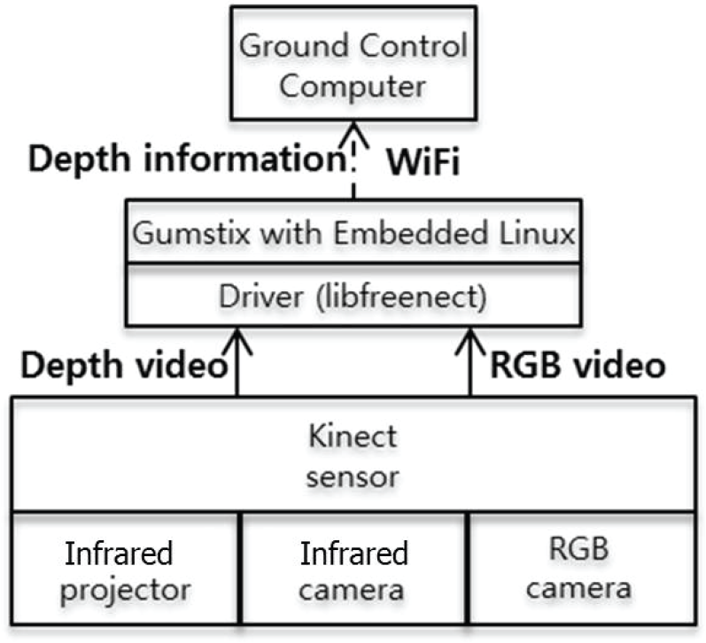
Collision detection system with the Kinect sensor flow chart
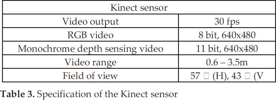
Table 3 and Figure 18 show the specification and camera array of the Kinect sensor.
Specification of the Kinect sensor
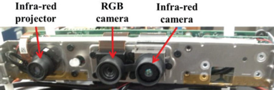
Camera array of Kinect
Table 4 shows the accuracy of the Kinect depth measurement. Based on the test, the accuracy of the Kinect sensor is at least 95%.
Accuracy test of Kinect sensor

Obstacles are detected using only the depth image. The original depth image which is obtained from the infrared camera has 640 × 480 pixels. This image is subsampled by 2 in both dimensions in the Gumstix embedded board to a 320 × 240 pixel image before transmitting to the GCS over the WiFi network. The collision detection system using the Kinect sensor is implemented in the GCS. That system will control the coaxial quadrotor depending on the obtained distance between coaxial quadrotor and obstacles.
Figure 19 shows the application of collision avoidance using a Kinect sensor. The detecting zone is 20cm (H) and 60 cm (W). If the obstacle is inside the zone, the application gives a warning message.

Collision avoidance application
5. Conclusion and future works
In this paper, we described the design and development of model-based control system for quadrotor and coaxial quadrotor systems. Our proposed quadrotor system is able to fly with a PID controller as the inner loop control. The established model included the same feedback control as that of the actual system. Since the system in simulation was slightly different to the real system, model improvement is envisioned for our future work. The gain parameters validated in the simulation based on modelling were used in the embedded controller to improve the performance of the quadrotor attitude control. The modelling and control system of the coaxial quadrotor were also established. Two different embedded board systems were used for the coaxial quadrotor control, one was used to control the attitude and the other for collision avoidance. A Kinect sensor was used for a collision detection system and the application of the Kinect sensor is developed by Visual C# and OpenCV. The experimental tests used to validate our approach were also successful.
Further investigation includes the comparative study of the application of various modern control methods for the entire flight envelope. A flight test with a collision detection system based on an indoor SLAM using 3D image data will be explored and implemented.