
Abstract
In this study, we design an autonomous navigation, guidance and control system for a small electric helicopter. Only small, light-weight, and inaccurate sensors can be used for the control of small helicopters because of the payload limitation. To overcome the problem of inaccurate sensors, a composite navigation system is designed. The designed navigation system enables us to precisely obtain the position and velocity of the helicopter. A guidance and control system is designed for stabilizing the helicopter at an arbitrary point in three-dimensional space. In particular, a novel and simple guidance system is designed using the combination of optimal control theory and quaternion kinematics. The designs of the study are validated experimentally, and the experimental results verify the efficiency of our navigation, guidance and control system for a small electric helicopter.
Keywords
1. Introduction
In the last decade, unmanned aerial vehicle (UAV) technology has improved drastically, and UAVs are now used not only in research and development but also for various practical purposes such as aerial photography, surveillance and crop dusting. UAVs are safer and more convenient than manned aircraft and they can potentially have a wide range of applications. It is necessary to achieve autonomous control of UAVs in order to reduce operator burden in practical tasks. Therefore, several researchers have focused on the autonomous control of various types of UAVs such as fixed-wing UAVs [1] [2], helicopter-type UAVs [3]–[7],tilt-rotor-type UAVs [8], tail-sitter-type UAVs [9] and airship-type UAVs [10].
Recently, small UAVs weighing less than 10kg have attracted considerable attention owing to their ease of carriage and handling. Accordingly, we have investigated methods for achieving autonomous control of a 2 kg small electric helicopter. However, it is extremely difficult to achieve autonomous control of small helicopters compared to large ones, owing to the payload limitation and sensor restriction. In general, larger sensors have greater accuracy. Hence, the sensors that can be mounted on 2 kg electric helicopters do not have enough accuracy for the requirements specification. Of course, some autopilot systems for small UAVs have already been proposed and developed [11]. However, in these autopilot systems, sensors are individually used to control each axis. For example, the Inertial Measurement Unit (IMU) is only used for attitude control, GPS for horizontal position and velocity control, and a barometer for height control. This configuration is not enough to control a small helicopter. In the case of a small helicopter, the accuracy and precision of a small GPS module is not enough for precise hovering and errors are caused in the barometer by down-wash from the rotor. These sensor errors should be compensated complementarily. Therefore, it is necessary for the autonomous control of a small helicopter to develop an integrated navigation system using multiple sensors. Meanwhile, the guidance system for small helicopters proposed in conventional works [3]–[7] is the full-state and coupling method. These methods are computationally expensive and not compatible with the small embedded computers that can be mounted on a 2 kg helicopter. Therefore, a simple and decoupled guidance method is desirable.
In this study, we design an autonomous navigation, guidance and control system for a small electric helicopter. There are two critical contributions in this paper. The first is an integrated navigation system using Extended Kalman Filter (EKF), and the second is a simple and decoupled guidance system. An integrated navigation system that consists of an inertial navigation, small, lightweight GPS module and a barometer are designed to obtain the accurate position and velocity of the helicopter. The guidance system is designed based on the combination of optimal control theory and quaternion kinematics. Flight experiments are conducted using a 2kg electric helicopter in order to validate the designed systems. Finally, accurate hovering and waypoint navigation of a small electric helicopter outdoors was achieved using a lightweight, inaccurate GPS module.
2. Experimental Setup
This section introduces the experimental setup including the small electric helicopter and all sensors and electric devices for control of the helicopter
Fig.1 shows the small electric helicopter Lepton-Ex, and its specifications are listed in Table 1. Lepton-Ex was originally designed as a hobby-use radio-controlled helicopter by HIROBO. Co. Ltd. The configuration of a control device is shown in Table 2. The control device consists of a Field Programmable Gate Array (FPGA) board, a small attitude sensor that was designed in [12],a small light weight GPS module, a barometer, a photo-reflector module for measuring rotor revolution, and a wireless module. The configuration of our control device is similar to standard autopilot systems for small UAVs introduced in [11]. However, the sensors we use have a problem with their precision. Although larger sensors have greater accuracy and precision, large sensors could not be used because of the payload limitation of small electric helicopters. Hence, the sensors do not have enough accuracy for the control of the helicopter. In particular, we address the problem of a small GPS module. For the operation of an autonomous helicopter, for example for aerial photography, hovering precision of the helicopter has to be at least around 1.5 m in calm conditions. The hovering error comprises the control error and the sensor error. Therefore, the position error of the GPS module has to be smaller than 1.5 m. However, the small GPS module does not give such precision. An example of some data from a small GPS module is shown in Fig.2. The solid line represents the position data from the small GPS module and the dashed line represents ground truth data obtained by RTK-GPS, the precision of which is 2 mm. It is clear from Fig. 2 that the precision and accuracy of a small GPS module is not enough to meet the requirements specification. For this reason, we design a composite navigation system to compensate the GPS module error.

Lepton-Ex small electric helicopter

Data from small GPS module
Specifications of Lepton-Ex

Specifications of control device

3. Composite Navigation System
In this section, a composite navigation system consisting of an inertial navigation system, a barometric height measurement, and the small GPS module, is designed to compensate the error described in the previous section. We use EKF to integrate all sensor outputs. By using the composite navigation system, the outputs of each sensor are compensated complementarily, and accurate position and velocity data could be obtained as a result.
3.1 Coordinate Systems
First, we introduce the four coordinate systems used for designing the composite navigation system and specify the vector notation for each coordinate system. The first coordinate system is the inertial frame. It is denoted by I-frame; its origin is fixed at the centre of the Earth. Zi indicates the Earth's polar axis; Xi and Yi pass through points on the equator. The second coordinate system is the Earth frame, and is denoted byE-frame; its origin is fixed at the centre of the Earth similarly to I-frame. Ze is the same as Zi; Xe passes through a point on the equator corresponding to 0deg longitude at any time, and rotates about Ze in conjunction with the rotation of the Earth. The third coordinate system is the navigation frame, and is denoted by N-frame; its origin is fixed at the centre of gravity of the helicopter. Xn is aligned with the true north, Zn with the direction of gravity, and Yn with the east. In addition, the navigation algorithm is calculated in N-frame. The last coordinate system is the body frame, and is denoted by B-frame; its origin is at the centre of gravity of the helicopter. Xb is aligned with the forward direction of the body, Yb with the rightward direction, and Zb with the downward direction. The output of an accelerometer is expressed as a vector in this frame (Fig.3). If an arbitrary vector in three-dimensional space is denoted by r, r is expressed in the frames defined above as

Coordinate system
3.2 Inertial Navigation
In this section, we present the derivation of the fundamental equations of inertial navigation. If V denotes the velocity vector of the helicopter, the navigation equation shown in [13] is obtained as

Generally, this equation holds not only for helicopters but for all moving bodies. Here, x denotes the vector product and

where

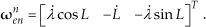
Here, L denotes the latitude of the current position of the helicopter. ω n en is a vector in N-frame, which expresses the angular velocity of N-frame relative to E-frame. Considering the longitude of the current position of the helicopter as λ, ω n en is expressed as
Lastly, g
n
is the gravitational acceleration vector and is simply expressed as


Here,

According to [13], the time derivatives of latitude L, longitude λ, and altitude h are obtained by using Rn and Re as follows:

Equations (5)–(7) and (9) are the fundamental equations of inertial navigation.
3.3 Barometric Height Measurement
GSPS accuracy of height and vertical velocity is quite low compared to the horizontal position and velocity data. Therefore, error of vertical direction has to be compensated by using additional sensors. In this study, we use a barometer to compensate the error, and in this section the relationship between the time derivatives of barometric pressure and the vertical velocity is derived for barometric height measurement. First, we consider an air column of height h, which is the same as the altitude of the helicopter (Fig.4); let ρ denote atmospheric density. Then, the relationship between the change in height dh and the change in air pressure dP is expressed as

Air column

Substituting the ideal gas law pRT = MP into (10), we could obtain

where R is the gas constant, T is the air temperature, and M is the molar mass of the air. Now, we divide (11) by the micro time dt; using the relationship between h andvd expressed in (9),the relationship between the time derivatives of the barometric pressure and the vertical velocity is derived as

In this equation, R, M, and g are constant; the air temperature T can be measured using the thermometer included in the MEMS barometer. Therefore, it is possible to calculate the vertical velocity on the basis of the change in barometric pressure.
3.4 Design of Extended Kalman Filter
In this section, we describe the design of the composite navigation system using the EKF. For designing EKF, a process model expressing the dynamics of the system is required. Therefore, we first derive the process model. The process model is derived on the basis of equations (5)–(7) and (9), inertial navigation and (12), and barometric height measurement.

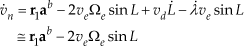
Here, wx, wy, and wz denote white noise. Introducing the vector b b a=[baxbaybaz], the true acceleration vector of the helicopter is obtained as a b -b b a , and (2) could be rewritten as
Therefore, (5)–(7) also could be rewritten, as follows:


Integrating (9), (12), (13), and (15)–(17), the nonlinear state-space equation could be obtained as follows:

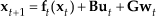
Digitizing the above equation, the discrete-time state-space equation could be obtained as
Next, the measurement equation is derived. Most of the small GPS module cannot output vertical velocity. Therefore, barometric pressure measured by the barometer is included in the output vector instead of the vertical velocity. Now, we consider the output vector of the system y t = [L λ h vn ve p] T , then, the measurement equation is derived as

Here, v t is the vector that expresses the measurement noise.
Now, let us consider

The extended Kalman filter algorithm is obtained as follows:

Here,

Block diagram of composite navigation system
3.5 Validation of Composite Navigation
To validate the designed composite navigation system, we carried out a validation experiment. In the experiment, whole devices including the GPS module were mounted on a cart, which was moved manually. An RTK-GPS was also mounted to obtain ground truth data. The navigation algorithm was calculated by using the computer embedded in the FPGA board. Fig.6 and Fig.7 show position and velocity data in the experiment. In these figures, the solid line represents the position and velocity data estimated by the composite navigation system. It is clear from Fig. 6 that the position was precisely estimated by the navigation system, even though the GPS data had a huge bias error in each axis.
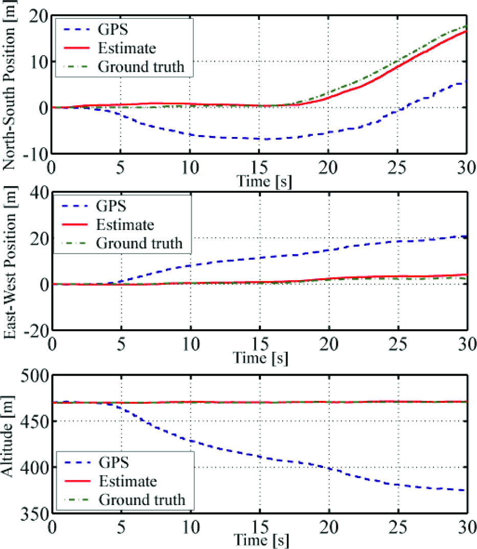
Validation result of composite navigation (position)
Fig.7 shows that the velocity was also estimated precisely. Next, Fig.8 and Fig.9 show a comparison of the navigation result with barometric height measurement and without it. It is clear that altitude and vertical velocity data without barometric height measurement show significant error. This shows the effectiveness of a navigation system with barometric height measurement.
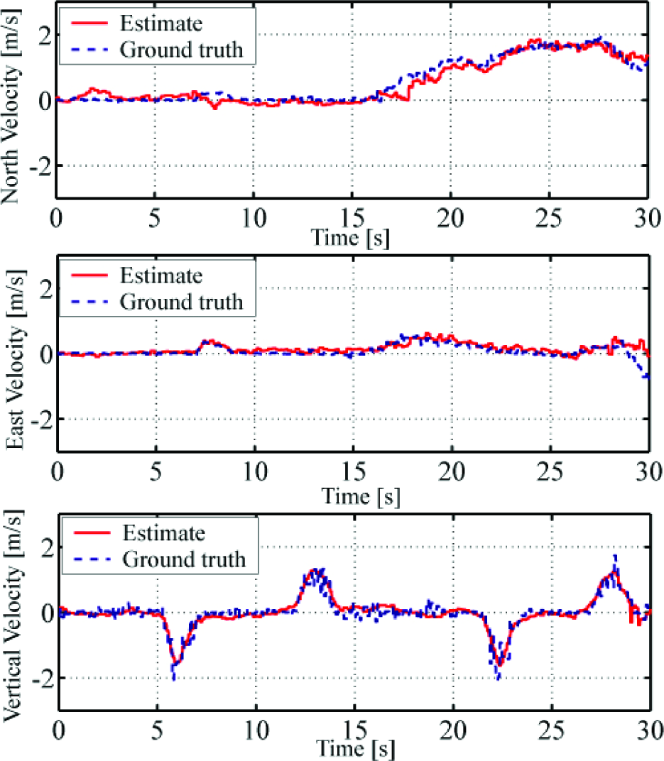
Validation result of composite navigation (velocity)

Comparison between With and Without barometer (altitude)
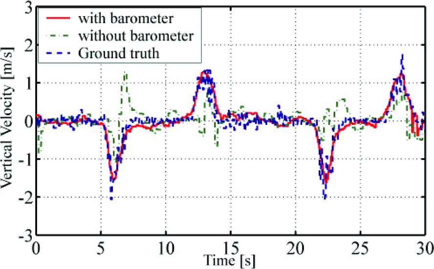
Comparison of data With and Without barometer (velocity)
From the results, it can be concluded that the designed composite navigation system was able to estimate precise position and velocity, even though the GPS module showed significant error.
4. Guidance and Control System Design
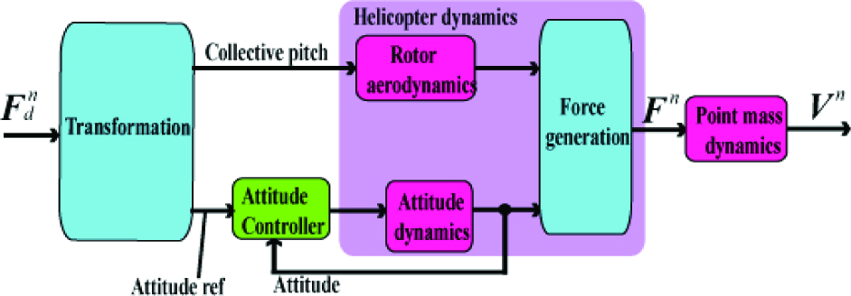
In this section, we describe the design of the guidance and control system for the small electric helicopter. The block diagram of the entire guidance, navigation, and control (GNC) system is shown in Fig.10. The attitude controller was designed in previous studies [14] and [15] and composite navigation was designed in the previous section. Here, we realize the three-dimensional guidance of the helicopter. The helicopter performs translational motion by changing the magnitude and direction of the thrust of the main rotor, and it is equivalent to changing the collective pitch angle of the rotor blade and the attitude of the helicopter. Therefore, it is necessary to calculate the appropriate collective pitch angle and attitude for realizing the guidance of the helicopter. In the following, we design a rotor revolution controller and guidance system. The rotor revolution controller, which stabilizes the rotation speed of the main rotor, is designed to simplify the design of the guidance system. Next, the guidance system itself, which calculates the appropriate collective pitch angle and the attitude of the helicopter, is designed for stabilizing the helicopter at an arbitrary point in three-dimensional space.

GNC system for small electric helicopter
4.1 Rotor Revolution Control System
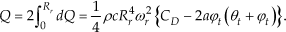
First, a mathematical model of the rotor revolution is derived for control system design. The source of power of our helicopter is an electric motor; therefore, we select the input voltage of the motor as the input and the angular velocity of the main rotor as the output. Table 3 lists the symbols used for model derivation. According to blade element theory [16], the resistance torque about the rotation axis of the rotor dQ, which is generated by blade element dr along the radius r of the blade, is expressed as

Notation for rotor modelling

Here, a is a two-dimensional lift curve slope and θ t and φ t are the blade pitch angle and the inflow angle at the blade tip (Fig.11). Considering that there are two blades, the total torque Q is obtained as
Next, the system equation of the electric motor is derived. The circuit equation of the motor is expressed as

The equation of motion of the motor is expressed as

Here, the second term on the right-hand side represents the viscous drag. From (24)–(26), we obtain


Definition of blade pitch angle and inflow angle
Here, we consider C̄D in (27) as C̄D = CD − 2aφt(θt + φt). Now, (27) is linearized around the hovering state. Assuming the angular velocity in the hovering state of Lepton-Ex is ωr0 [rad/s], a small fluctuation in the angular velocity from the hovering state is defined as
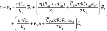
Here, v0 is the input voltage to the motor in the hovering state, and is obtained from (27) as

Here, the first, second and fourth terms in (27) are zero because ωr0 is constant. Additionally, C̄D is assumed to be constant in the hovering state. If a small fluctuation in the input voltage from the hovering state is defined as v̄ = v − v0 (28) could be transformed using Laplace transformation; then, rearranging the equation, the transfer function of the system is obtained as

Here,

where Rm, Lm, J, and μ are unknown parameters in this model. In this study, we have determined the values of these unknown parameters by comparing the experimental data with the output of the model. The value of each parameter is listed in Table 3 and the comparison result is shown in Fig.12. The solid line represents the model output and the dashed line represents the rotor revolution data obtained in the experiment.
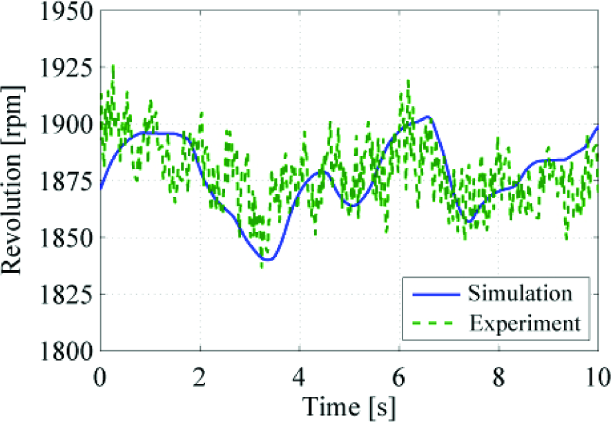
Validation result of rotor revolution model
Next, the revolution controller is designed by using optimal control theory. First, the minimum realization of the transfer function (30) is derived as

Here, xr is defined as

Now, the servo augmented system [17] is constructed as
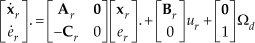
Here, Ω d is desired angular velocity fluctuation from the hovering state and er is the integral of the error between desired and current angular velocity of the rotor. When we stabilize the angular velocity of the rotor to ωr0, Ω d could be setas zero. Considering x̄ r as the state vector of the servo augmented system, we introduce the criterion

The feedback gain

Here,

Using

In addition, the state vector x̄ i is estimated by the observer in the experiment because we can only measure the angular velocity of the rotor.
4.2 Guidance System
In this section, we design the guidance system for stabilizing the helicopter at an arbitrary point in three-dimensional space. The system is designed in two steps. First, we design a guidance controller that calculates the force vector required to stabilize the position and velocity of the helicopter. For simplicity, the helicopter could be considered as a point mass with inner loop dynamics. Second, we design a force generator that calculates the appropriate collective pitch angle of the rotor and the reference attitude for achieving the desired force by using the rotor thrust.
4.2.1 Guidance Controller
First, the mathematical model of the translational dynamics of the helicopter is derived. The entire system of the translational dynamics is shown in Fig.13. The input of the system is the desired force vector

Translational dynamics of the helicopter

Point mass model
where the mass of the helicopter is denoted by m. Additionally, the second term on the right-hand side represents attenuation term by air drag, and
On the other hand, the dynamics between

Finally using (40) and (41), the transfer function from

This transfer function was uniformly applied to each axis.
Next, the guidance controller is designed using the derived model, considering the latitude, longitude, and altitude of the target point as Ld, λ d , and hd respectively. Then, the velocity required to make the helicopter move to the target point is calculated, using proportional control as

Here, vnd, ved and vdd denote the desired velocities in the north, east, and downward directions, and K, K and Kpd denote the positive gain. Next, the velocity controller, which guarantees the velocity of the helicopter follows requirements, is designed using optimal control theory. First, the realization of the transfer function of (42) is expressed as

The subscripts denote the direction (north, east, or downward); fdi is each axis component of

An identity observer is designed for each axis to estimate unmeasured state in the experiment.
4.2.2 Force Generator
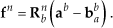
The force generator calculates the appropriate collective pitch angle of the main rotor and the desired quaternion [18] that expresses the attitude required to realize the desired external force

Here, KT is a constant determined by the shape and rotation speed of the main rotor. Therefore, the collective pitch angle for achieving the desired external force could be obtained as

Next, the quaternion that expresses the reference attitude is calculated. Now, we design a simple method for obtaining the desired quaternion using Single Rotation (SR) [18]. For the purposes of the design, the fifth coordinate system, reference frame, is defined. The reference frame is denoted by R-frame; its origin is fixed at the centre of gravity of the helicopter. Zr is the same as Zn. This frame rotates the desired heading angle of the helicopter, Ψ
d
, about Zr (Fig.15). Considering the quaternion to express the attitude of R-frame relative to N-frame as


Definition of R-frame
According to [18], considering

Here, ⊗ represents the quaternion product. Now, we define the desired thrust vector that indicates upward of
R-frame as

Using this SR, the quaternion

where c(x) = cosx and s(x) = sinx, λ
dx
, λ
dy
, and λ
dz
are the components of λ
d
along each axis Finally, the desired quaternion

The desired external force could be achieved by using (47),(52) and the attitude control system designed in previous studies.
5. Experiments
Experiments were carried out to validate the proposed guidance and control systems. The results are presented in the following sections. The parameters used for the design of the guidance and control system are listed in Table 4.
Design parameter

5.1 Rotor Revolution Control Experiment
First, the revolution control experiment was carried out on the ground. In this experiment, the helicopter was stationary on the ground and the rotor revolution reference was expressed by a step signal. Fig.16 shows the result of the experiment. The solid line represents the rotor revolution measured by the photo reflector module, and the dashed line represents the reference revolution. This figure clearly shows that the rotor revolution precisely follows the reference revolution.

Revolution control on the ground
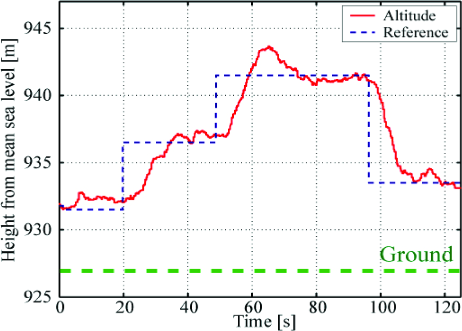
Next, a flight experiment was carried out. In this experiment, only the rotor revolution was controlled, and the other axis was controlled manually. In addition, the reference revolution was expressed as a constant because it is necessary to stabilize the rotor revolution to a constant value for (46). The result is shown in Fig.17 and Fig.18.
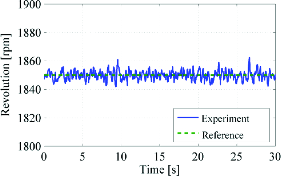
Revolution control in flight (revolution)
Revolution control in flight (vertical velocity)
Fig.17 shows the rotor revolution and Fig.18 shows the vertical velocity. The rotor revolution could be stabilized to a constant value even if the helicopter moved upward (10 s) or downward (17 s). From the result, the rotor revolution can be considered as constant in flight, and so the assumption for (46) could be satisfied.
5.2 Guidance Control Experiment
Finally, three-dimensional guidance control experiments were carried out. The experiments were conducted outdoors. The average wind speed was approximately 1–2 m/s. Fig.19 and Fig.20 show the 3-D and 2-D trajectories in the hovering experiment. The reference position has been fixed at the origin. The figure shows that 95% of the entire flight trajectory was included in the 0.5 m ball centred at the origin.

Hovering experiment (three-dimensional trajectory)

Hovering experiment (two-dimensional trajectory)
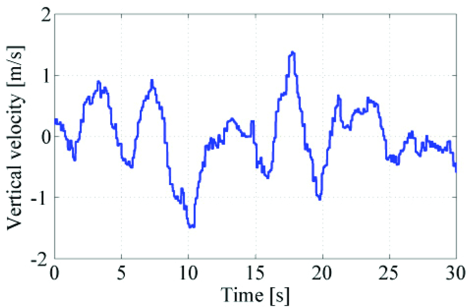
Fig.21 and Fig.22 show the horizontal and vertical trajectories of waypoint flight. In this experiment, the waypoint was expressed from a ground station via wireless communication. The figure clearly shows that the helicopter accurately passed each waypoint both horizontally and vertically.

Waypoint flight
Altitude control
From the results, it can be said that the hovering error is< 1.5 m, and so the navigation, guidance and control system designed in this paper satisfy the requirements specification for an autonomous helicopter.
6. Conclusion
In this paper, we presented the design of a composite navigation system and a three-dimensional guidance and control system for a small electric helicopter. A novel composite navigation system was developed using an inertial navigation, a barometric height measurement, and an inaccurate GPS module. A simple method was suggested for calculating the reference attitude and the collective pitch angle of the main rotor in order to realize three-dimensional guidance of the helicopter. The experimental results verified the effectiveness of the proposed navigation, guidance and control systems. In the future, we plan to realize automated take-off and landing and to achieve fully autonomous cooperative control of multiple helicopters.