
Abstract
This paper presents the design and implementation of an automatic battery swap system for the prolonged activities of home robots. A battery swap station is proposed to implement battery off-line recharging and on-line exchanging functions. It consists of a loading and unloading mechanism, a shifting mechanism, a locking device and a shell. The home robot is a palm-sized wheeled robot with an onboard camera and a removable battery case in the front. It communicates with the battery swap station wirelessly through ZigBee. The influences of battery case deflection and robot docking deflection on the battery swap operations have been investigated. The experimental results show that it takes an average time of 84.2s to complete the battery swap operations. The home robot does not have to wait several hours for the batteries to be fully charged. The proposed battery swap system is proved to be efficient in home robot applications that need the robots to work continuously over a long period.
1. Introduction
With the rapid development of home automation on a global scale in recent years, mobile robots are increasingly used in home environments [1]. Home robots are widely used in home automation services such as cleaning, security, rehabilitation training, and homecare. Owing to advances in Microelectromechanical System (MEMS) technology, the size and cost of home robots have been reduced significantly. More and more people want to use home robots to make their lives more intelligent, easier and more enjoyable [2]-[4].
Taking into account the needs of users, home robots must exhibit some self-sustaining property. In addition to being robust in their hardware and software design, home robots must have autonomous capabilities for long-duration missions. Renewable energy sources are therefore of great concern [5]. Solar cells or rechargeable batteries are the most commonly used energy sources for mobile robots. Calderon et al.[6] use triple-junction solar cells to provide continuous power supply to a mobile robot. But this is not suitable for home robots which work in indoor environments, so using rechargeable batteries is a feasible method to increase long-term autonomy. However, most current home robots have to have their batteries replaced by human operators. People prefer robots to be able to do this job automatically.
Several methods have been proposed for the automatic recharging station of home robots. Luo et al. [7] present a concept of recharging station for home robots. The station consists of an automatic recharging device and a robot docking mechanism. Song et al.[8] present a surveillance robot with automatic docking and recharging capabilities for home security and implement the design of a simple semi-circular recharging station. Home robots must be designed to dock themselves into the station to recharge their batteries. Parker and Zbeda [9] propose a recharging station for super capacitors of a legged robot. The level of power that the capacitors can hold is determined by the capacitance value. The mechanism of the station is very simple. It is only composed of a piece of wood and two metal plates, which connect to a power supply. Chen et al.[10] propose a contactless recharging station which is based on Inductive Power Transfer (IPT). The battery finishes charging within about three hours.
Compared with the recharging stations mentioned above [7] [8], the recharging station for super capacitors and the contactless charging station make it much easier for home robots to dock. But the super capacitors are expensive and not reliable as the source of power for the motors, so using the off-the-shelf recharging batteries is a better solution than using the capacitors. The efficiency of the wireless charging is much lower than the direct charging. It should be noted that the activities of the autonomous home robots must be interrupted during the battery-charging process. Many tasks must be sustained 24 hours a day, such as security and surveillance. Thus, a battery recharging station is not applicable to solve this problem.
Therefore, the method of automatic battery swap is a good solution to solve the problem of continuous work in home robot applications. Saito et al.[11] introduce a battery exchanging system composed of a support robot and a recharging station. If the energy of the work robots is insufficient, the support robot approaches and docks with the work robots. Then it delivers the fresh batteries to the work robots and takes the batteries to the station for recharging. Some researchers propose a ground station that can exchange the batteries for the Unmanned Aerial Vehicles (UAVs) [12]-[14]. Jung et al.[15] introduce a new complete passive battery docking and exchanging mechanism for mobile robots. The system compensates a wide range of offsets between the battery and the recharging station. But the UAVs [12]-[14] and the mobile robots [15] need to be powered off during the battery exchange process. This may cause damages of the control system due to this kind of design. Wu et al.[16] present a novel design of robot docking station for automatic battery exchanging and charging. In contrast to the system proposed by Saito et al.[11], this battery swap station does not need an additional robot for the exchanging process.
Apart from the design of battery swap and recharging stations, the docking guidance algorithm is equally important. Some vision-based docking algorithms are presented [17]-[19]. The results all show that the proposed methods provide a high level of robustness and precision. But the robot needs to be equipped with a laptop and an HD camera, and therefore the methods are not suitable for small home robot applications due to cost and size limitations. Luo et al. [20] propose a power recharge station searching method based on sound source detection for autonomous mobile robot applications. Niu et al. [21] use two pairs of infrared LEDs to guide the robot to dock in the recharging station. Kim et al. [22] propose a homing system that utilizes cheap infrared sensors for mobile robots. An infrared LED array divides a 150-degree area at the front of the recharging station into nine regions. The success rate of docking is over 95%.
Most current home robots lack autonomy capability in long-duration missions. They either have to have their batteries replaced by human operators, or stay in the recharging stations for several hours before their batteries are fully charged again. In order to solve this problem, an automatic battery swap system for the prolonged activities of home robots is presented in this paper. It provides the functions of battery off-line recharging and on-line exchanging. The home robot does not have to wait several hours for the batteries to be fully charged. Details of the design work and the experimental results are given in the following sections.
2. System Architecture
The conceptual architecture of the proposed battery swap system is shown in Figure 1. It is specifically designed to continually provide newly charged batteries for home robots that have to work long hours. Before the home robot runs out of energy, it returns to the battery swap station to replace the spent batteries with the charged batteries. A prototype of the home robot for home security applications is shown in Figure 2. It is a palm-sized wheeled robot with an onboard camera and a removable battery case in the front. A prototype of the battery swap station is shown in Figure 3. It communicates with the home robot wirelessly through ZigBee.

Conceptual system architecture. The home robot returns to the battery swap station to replace the spent batteries with the charged batteries.

The home robot with a removable battery case in the front.

The battery swap station.
2.1 Mechanism Design
The battery case made of acrylic glass can hold six AA batteries, as shown in Figure 4. Its mechanical structure is shown in Figure 5. A T-shaped handle is installed in the front. When the handle rotates, the gear racks will be stuck out from both sides to lock the battery case in the charging holder of the battery swap station. If the gear racks retreat into the battery case, the battery case will be unlocked and ready for sliding forward and backward.

The battery case.

Mechanical structure of the battery case.
The mechanical structure of the battery swap station is shown in Figure 6. It consists of a loading and unloading mechanism, a shifting mechanism, a locking device and a shell. The loading and unloading mechanism includes a servo, a DC motor, a gripper and a lead screw. This mechanism is responsible for unloading and loading the battery case from and to the home robot. The C-shaped gripper can catch the handle of the battery case and rotate it to lock or unlock the battery case, as shown in Figure 7. During the battery swap process, the rotation actions of the gripper can be delineated into five steps. When the battery case is unlocked between C and D steps, the servo stops and the DC motor 1 starts to drive the gripper to move along the lead screw 1. The battery case is thus pushed in or pulled out of the charging holder.
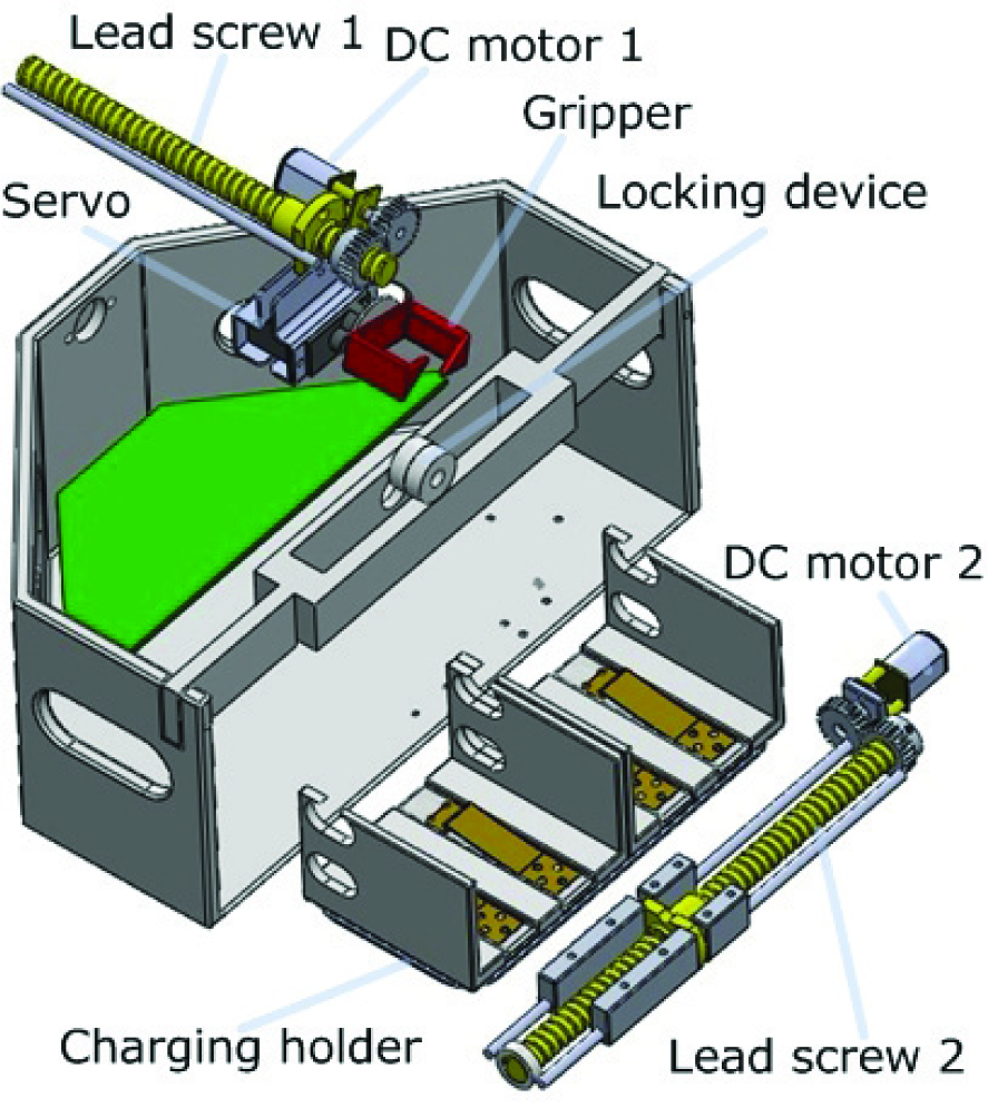
Mechanical structure of the battery swap station.

Action decomposition of the gripper during the battery swap process. The battery case is pushed in or pulled out of the charging holder between C and D.
The shifting mechanism consists of a DC motor, a lead screw, and a charging holder with two charging slots. This mechanism is responsible for moving away the spent batteries unloaded from the robot and pulling back the charged batteries. When the mechanism starts to work, the DC motor 2 drives the lead screw 2 to rotate. Then the charging holder will be dragged to move along the lead screw 2.
The locking device in the front of the shell is an auxiliary device for docking of the home robot. It is composed of an electromagnetic sucking disk and a thin-film pressure sensor. The pressure sensor is pasted on the surface of the electromagnetic sucking disk. When the home robot reaches the docking area, the sucking disk is powered onto generate electromagnetic force that attracts the robot to dock with the battery swap station. When the metal head of the home robot touches the locking device, the pressure sensor will detect the touch force. Therefore both the home robot and the battery swap station will know when the docking actions succeed. The battery swap operations may then begin. During the battery swap process, the locking device ensures that the home robot does not deviate from its final docking position. When the battery swap process ends, the electromagnetic sucking disk ispowered off and the electromagnetic force disappears. The home robot with charged batteries can then return to work again.
2.2 Hardware Modules
The hardware architecture of the battery swap station is shown in Figure 8. A prototype photo of the hardware modules of the battery swap station is shown in Figure 10. The hardware modules are designed to implement motor control, sensor data acquisition and communication with the home robot. The kernel chip is a 32-bit ZigBee compliant microcontroller that enables multiple battery swap stations and home robots to form wireless multi-hop communication networks. There are three kinds of power supplies in the hardware modules which provide different DC output voltages ranging from 3.3V to 24V.

Hardware diagram of the battery swap station.
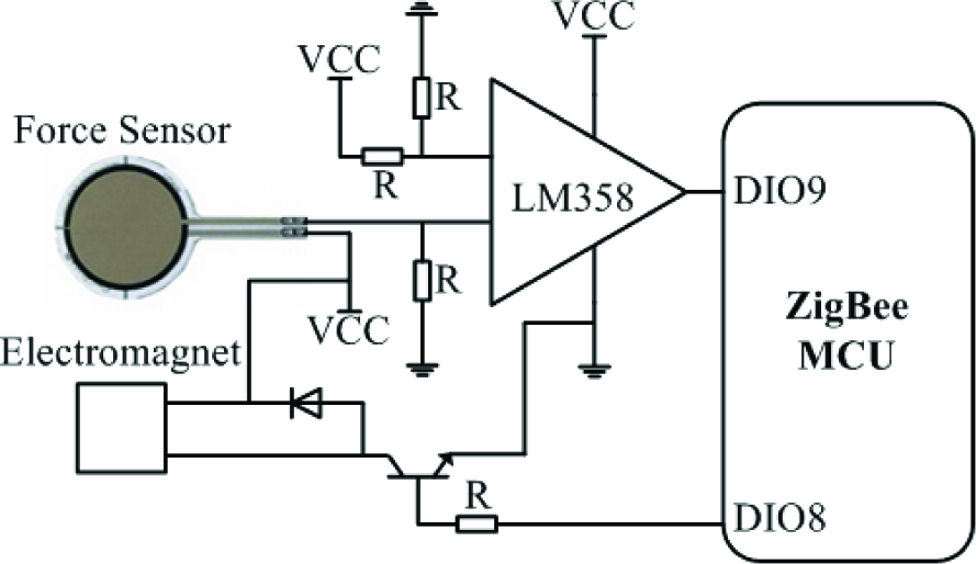
Docking status monitoring circuit.
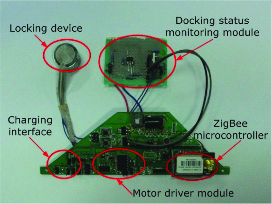
Implemented hardware modules of the battery swap station.
The two DC motors are the same but they do not work simultaneously during the battery swap process, so we use only one I/O port of the microcontroller to control the two DC motors. An analogue switch IC is used to implement time shared control. A motor driver IC is used to implement simultaneous, bidirectional control of the two DC motors. The forward/reversal rotation of the two DC motors is implemented by altering the input levels of the motor driver IC.
The docking status monitoring circuit is shown in Figure 9. The pressure sensor can output different resistance values according to different external pressures. It serves as a variable resistor that is connected to the input end of the dual operational amplifier LM358. When no external pressure exists, the variable resistor achieves its maximum resistance value. Its resistance value decreases with an increase in the external pressure. Since the electromagnetic sucking disk only works during the battery swap process, we use a transistor to shut off its power when the battery swap process ends.
The charging circuit is based on a 6–7.2V Ni-MH battery pack charger which can provide up to 400mA of output current. In order to prevent reflux when the charger charges the two battery cases at the same time, the charging circuit uses two identical diodes to restrict the current flow. The microcontroller can judge if the battery case is swapped by monitoring the input voltage changes of the two ADC pins connected to the charging circuit.
2.3 Software Modules
When the home robot is running out of its onboard batteries, it will abort its current mission, send the return-to-base message and return to the battery station. The firmware process of the home robot for battery swap is shown in Figure 11.

Firmware process of the home robot for battery swap.
When the home robot receives the stop message from the battery swap station which indicates the docking actions are complete, it will shut down its wheel motors, switch to the backup batteries and send the ready-for-swap message. If the home robot detects that the battery case has been swapped successfully, it switches to the main batteries, starts the wheel motors and returns to work again. The home robot judges that the battery swap operations fail unless two conditions are met. One is that the swap-succeeded message is received. The other is that the output voltage of the battery case returns to normal.
The firmware of the battery swap station implements two major functions, one of which is to assist the home robot to complete the docking operations and the other is to complete the battery swap operations. The firmware process of the battery swap station is shown in Figure 12. When the battery swap station receives the return-to-base message from the home robot, it powers on the locking device to prepare for docking of the home robot. The electromagnetic attractive force generated by the sucking disk can guide the home robot in the final step of the docking process. It helps reduce docking errors and docking times. When the locking device detects pressure on the sucking disk and the battery swap station receives the ready-for-swap message from the home robot, the battery swap process starts.

Firmware process of the battery swap station.
The battery swap operations depend on the cooperation of the loading/unloading mechanism and the shifting mechanism. The loading/unloading mechanism first unloads the spent battery case from the home robot and puts it into one of the charging slots for charging. Then the shifting mechanism moves away the spent battery case and pulls back the charged battery case to make it align with the home robot. Finally, the loading/unloading mechanism loads the charged battery case onto the robot. When the battery swap process ends, the locking device is powered off and the battery swap station sends the swap-succeeded message.
3. Experimental Results
Some experiments have been done to evaluate the performance of the proposed battery swap system. The influences of battery case deflection and robot docking deflection on the battery swap operations have been investigated. A complete battery swap process has been recorded by a video camera and selected video frames are shown in Figure 13. In A, B and C, the spent battery case is unloaded from the robot to the charging holder. In D, E and F, the charging holder moves away the spent battery case and brings back the charged battery case to align it with the home robot. In G, H and I, the charged battery case is loaded onto the home robot. The average time taken for the battery swap process is 84.2s, as shown in Figure 14.

Selected video frames showing the battery swap process.
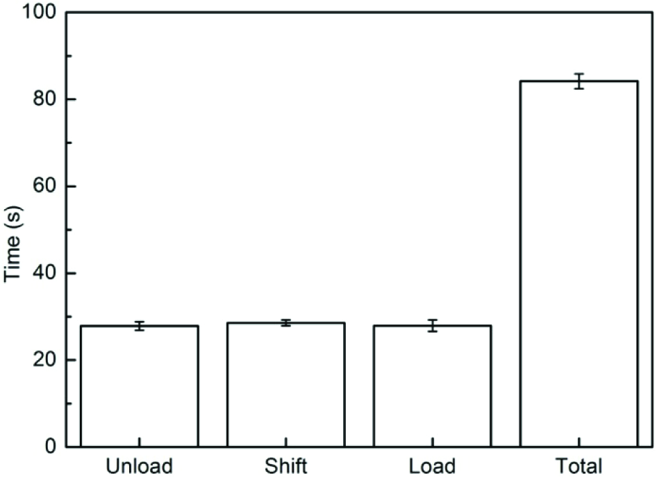
Average time consumed during the battery swap process.
When the battery case is pulled into the charging holder, the rotation of the gripper will make the battery case deviate from its ideal sliding trajectory, as shown in Figure 15. The deflection is directly related to the step speed of the servo. The rotation speed of the servo is fixed as 60 degrees/0.1s. When we set the desired angle of the servo immediately, the servo rotates to the desired angle at that full speed. It will cause a great deflection of the battery case. We use a multi-step method to achieve the desired angle. Therefore, the step speed of the servo is reduced in the process. The step speed of the servo is adjusted by changing the step angle. When the gripper is catching the handle of the battery case, its two claws cannot touch the handle simultaneously. That causes unbalanced touch forces on the handle. Therefore the battery case is driven to deflect to some degree. If the deflection angle is too big, the battery case will collide with the inner side of the charging holder and even fail to enter the charging holder. The deflection angles of the battery case under different servo step speeds are shown in Figure 16. When the servo rotates 45 degrees per step, the deflection angle is about 4.6 degrees. Although it takes the shortest time to pull the battery case at this speed, we set the safe step speed to 11.25 degrees per step to reduce the risk of failed operations.

Deflection of the battery case caused by the rotation of the gripper when it enters the charging holder.

Deflection angles of the battery case under different servo step speeds. The servo rotates 45/m degrees per step (m=1, 2, 3, 4, 5).
The docking deflection of the home robot will also have an influence on the battery swap operations. As shown in Figure 17, the black point at the origin of the Cartesian coordinate system represents the ideal docking position. The white point represents the actual docking position. The docking deflection of the robot can be expressed by three parameters, i.e.,Dx, Dy and θxy. The influences of the three parameters on the success rate of the battery swap operations have been investigated.

Docking deflection of the home robot. The black point at the origin of the Cartesian coordinate system represents the ideal docking position. The white point represents the actual docking position. Dx and Dy are the horizontal deflection and the vertical deflection between the white point and the black point along the X-axis and the Y-axis respectively. θxy is the angle of the centreline of the robot and the Y-axis.
As shown in Figure 18(a), we set Dy=0mm, θxy=0 degree. So Dxmax = ±1/2*min (Wcpt -Wbox, Wpaw - Whandle)= ±8mm, where Wcpt, Wbox, Wpaw and Whandle are the widths of the battery compartment, the battery case, the gripper and the handle. As shown in Figure 18(b), we set Dx=0mm, θxy=0 degree. So Dymax = ±1/2*min(Dpaw, Dpaw-Dhandle)=±7.5mm, where Dpaw is the distance between the battery compartment and the battery case. Dhandle is the diameter of the handle of the battery case. When θxy=0 degree, we change Dx (Dy) within the theoretical tolerance limits of ±8mm (±7.5mm) at a step of 2.5mm. The success rates of the battery swap operations under these conditions are shown in Figure 19. When |Dx|≤2.5mm, the success rate is above 90%. When |Dx|≥7.5mm, the success rate decreases below 70%. When |Dy| ≤7.5mm, the success rate is above 70%. When Dy >7.5mm, the gripper cannot catch the holder of the battery case, the battery operations will always fail. When Dy= −7.5mm, it reaches the negative tolerance limit. The handle will touch the inner side of the gripper and Dy cannot increase any more.

The limit value of Dx and Dy.

Success rate of the battery swap operation when θ xy =0 degree.
When θxy≠0 degree, we define θxy as negative (positive) when the tail of the home robot deflects to the left (right) side of the Y axis. Since all the system is symmetrical to the Y axis, we only investigate the success rates of the battery swap operations when Dx and θxy are both positive. We increase Dx at a step of 2.5mm and θxy at a step of 3 degrees. The experimental results are shown in Figures 20 to 23.

Success rate of the battery swap operation when Dx=0mm.

Success rate of the battery swap operation when Dx=2.5mm.

Success rate of the battery swap operation when Dx=5mm.
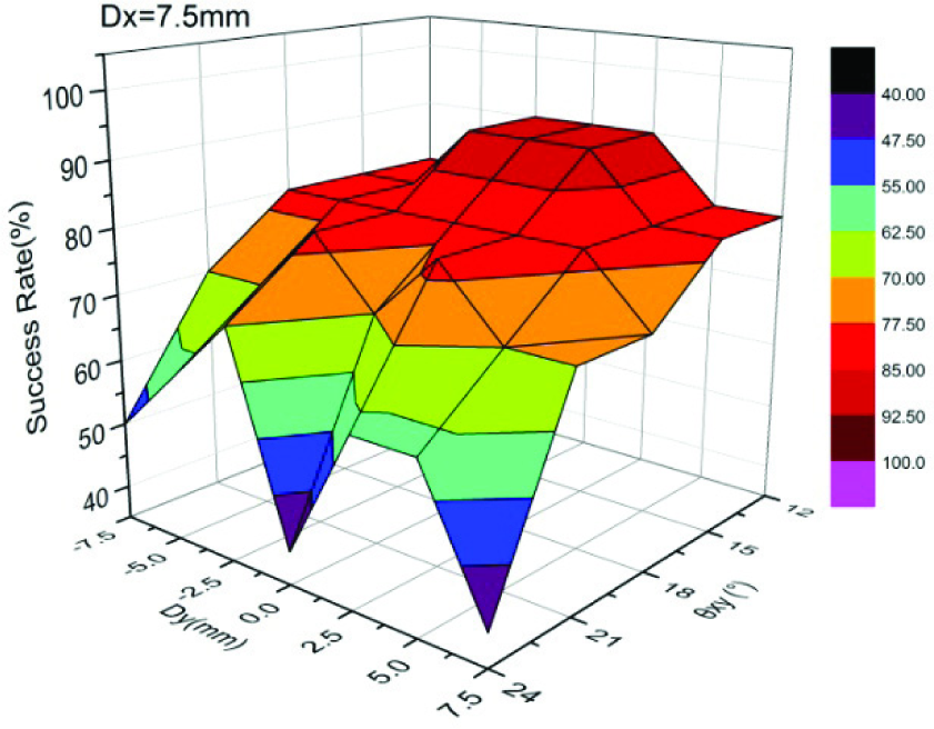
Success rate of the battery swap operation when Dx=7.5mm.
The success rate increases with the increasing Dx when θxy remains unchanged. If we set 70% as the threshold of the success rate, we can get four limit values of θxy, i.e., 21 degrees when Dx=0, 21 degrees when Dx=2.5mm, 18 degrees when Dx=5mm, and 15 degrees when Dx=7.5mm.
4. Conclusion
In this paper, we have presented the design and implementation of an automatic battery swap system for the prolonged activities of home robots. A battery swap station is proposed to implement battery off-line recharging and on-line exchanging functions. Many indoor tasks which must be sustained 24 hours a day can be successfully carried out by home robots with the assistance of this battery swap station. Unlike other existing systems, our home robot need not be shut down during the battery-exchanging process, meaning it can continue to do its work without restarting. A simple electromagnetic locking device with a docking status monitoring mechanism is designed to replace the traditional complex mechanical locking structures, making it easier and more flexible for the home robot to complete the docking and battery exchanging operations.
The experimental results show that it takes an average time of 84.2s to complete the battery swap operations. The success rates of the battery swap operations under different home robot deflection conditions have also been tested. In our future work, we plan to further reduce the size of the battery case and improve the docking method to decrease docking deflections.
Footnotes
5. Acknowledgments
The research reported in this paper was carried out at the Robotic Sensor and Control Lab, School of Instrument Science and Engineering, Southeast University, Nanjing, Jiangsu, China.
This work was supported in part by the Natural Science Foundation of China under grants 60875070 and 60905045, the Natural Science Foundation of Jiangsu Province under grants BK2009103 and BK2011254, and the Program for New Century Excellent Talents in University under grant NCET-10-0330.