
Abstract
Recently the component-based approach has become a major trend in intelligent service robot development due to its reusability and productivity. The framework in a component-based system should provide essential services for application components. However, to our knowledge the existing robot frameworks do not yet support fault tolerance service. Moreover, it is often believed that faults can be handled only at the application level. In this paper, by extending the robot framework with the fault tolerance function, we argue that the framework-based fault tolerance approach is feasible and even has many benefits, including that: 1) the system integrators can build fault tolerance applications from non-fault-aware components; 2) the constraints of the components and the operating environment can be considered at the time of integration, which – cannot be anticipated eaily at the time of component development; 3) consistency in system reliability can be obtained even in spite of diverse application component sources. In the proposed construction, we build XML rule files defining the rules for probing and determining the fault conditions of each component, contamination cases from a faulty component, and the possible recovery and safety methods. The rule files are established by a system integrator and the fault manager in the framework controls the fault tolerance process according to the rules. We demonstrate that the fault-tolerant framework can incorporate widely accepted fault tolerance techniques. The effectiveness and real-time performance of the framework-based approach and its techniques are examined by testing an autonomous mobile robot in typical fault scenarios.
Keywords
1. Introduction
Service robots have recently attracted increasing interest in research and industry. Carnegie Mellon University's Minerva, Honda's Asimo, Sony's AIBO and iRobot's Roomba are just a few examples [1]. However, service robots are complex computer and control systems consisting of a number of integrated hardware and software modules, such as sensors, actuators, controllers, signal processing, artificial intelligence and human-interface algorithms. Furthermore, the robot's modules cooperate to achieve specific tasks. Due to their need for tight integration with the physical world and their unique characteristics, service robots in general pose considerable impediments and make the development of robotic applications challenging.
To overcome these integration difficulties in robot system development, various proposals for robot middleware or frameworks have been proposed [2]: for example, MIRO, Orca, UPnP middleware, RT-middleware and OROCOS. More recently the component-based design has become the trend of robot software frameworks because of the benefits of modularity, reusability and productivity. Fig. 1 shows the typical system structure of component-based robot systems, illustrating the components as so-called ‘Lego’ blocks and the framework as a mainframe. In addition to providing specific application functions, the components follow a well-defined design pattern and interface so that the framework can control the lifecycle, execution and data-passing of the components. The representative systems include OMG's RTC (Robot Technology Component) [3], Microsoft's MRDS (Microsoft Robotics Developer Studio) [4], ROS (Robot Operating System) [5] and OPRoS (Open Platform for Robotic Services) [6–8].
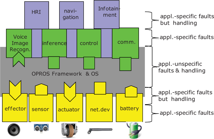
Typical System Structure of Component-based Robot Systems
On the other hand, for the commercial success of intelligent service robots, fault tolerance technology for system reliability and human safety is crucial [9, 10]. This is because mobile service robots operate with moving mechanical parts in the human working space. Since fault tolerance operations are typically a system or application level function, it is extremely difficult, if not impossible, to design a fault tolerance procedure at the component development stage. In other words, component developers have limited knowledge of the integration and operating environment of the component. This separation of roles between component-developers and system integrators in component–based development highlights the difference in the fault tolerance function from the earlier robot development process [11]. Therefore, the framework must support fault tolerance service as a framework service. However, to our knowledge, the existing component-based robot software frameworks, including those mentioned above, do not yet provide an appropriate level of fault tolerance support. We believe that this lack of fault tolerance in the existing frameworks is mainly due to designers' understanding of fault tolerance as application-dependent and the framework as application-independent in nature.
Note that the key design difference of service robots from other types of robot, e.g., industrial robots, is that the robot applications are not fixed. For fixed applications and devices, we can install fault-tolerance mechanisms customized for those systems and applications. On the service robot, however, we have new and varying applications, which require a new approach such as the one in this paper.
In this paper, we show that a fault tolerance-aware framework with operation rule files can automate fault tolerance instrumentation very well in component-based robot systems. First we prepare the framework with appropriate fault-tolerant functions for common fault patterns in components and applications of service robot systems. Then, the system integrators merely have to declare fault tolerance rules in configuration descriptors and/or add simple monitor components considering the constraints of the components and the operating environment. Thus, our proposal requires no or little change in existing application components and application design. In this paper, we implement a fault-tolerant framework based on the OPRoS platform [6–8] and a prototype robot. By exposing the system to various fault scenarios, we demonstrate the feasibility, benefits and design examples of the proposed approach.
The remainder of the paper is organized as follows. Starting with a brief description of the OPRoS component-based robot software framework, Section 2 presents the proposed framework-based fault tolerance architecture. In Section 3 we describe how to integrate typical fault-tolerant techniques into the proposed framework. The representative application scenarios are explained using our robot system. In Section 4, we examine the real-time performance aspects of the framework and rule-based fault tolerance. Section 5 concludes this paper with a few future work directions.
2. Fault-tolerant Framework Design
In this section we describe the role and general operating mechanisms of component-based robot software frameworks, with OPRoS as an example framework. Then we describe how the framework can be extended for supporting fault tolerance service and how the proposed architecture can provide benefits to robot system developers, application component developers and end users.
2.1 OPRoS: A Component-based Robot Framework
A detailed description of OPRoS standards might be required for an implementation-level understanding of our proposed fault-tolerant architecture and mechanisms, but readers can understand the general operation using Fig. 2 and the following quick summary. For a detailed description, readers should refer to the specifications [6], overview paper [7] and the OPRoS project website [8], where the framework implementation source, sample components, utilities and presentation materials can also be downloaded.

The OPRoS Framework and Component Model
The OPRoS robot system consists of an OPRoS framework engine and application components. The OPRoS components provide application-specific services, e.g., sensors, actuators and various algorithm components. The OPRoS component specification uses the C++ language and utilizes the object-oriented programming model.
The OPRoS framework runs as a process in an operating system and provides the execution, lifecycle management, configuration and communication services to the application components. The framework manages the lifecycle of the components, such as loading/unloading the component library and creating/destroying an instance, the state of the components using lifecycle interface functions, initialize(), start(), stop(), destroy(), recover(), update() and reset(). The framework also executes the components' functions by invoking the callback functions, that is, onExecute() and onEvent(), defined in the user components.
A user-defined OPRoS component class inherits the basis class ‘Component’ and overrides the callback functions. When its callback functions are called, a component can execute its jobs and communicate data with other components only through ports. OPRoS ports are classified as ‘data’, ‘event’ and ‘service’ according to the synchronization and argument styles. For some cases, multiple atomic components can be merged into a ‘composite’ class, which is again treated as a component.
For the system integration mechanism, the component configuration information, such as the component name, port name, port type and execution type, is provided in an XML file called the ‘component profile’. The components are grouped into application tasks in another XML file called the ‘application profile’. The application profile provides the port connection information and initialization values for the components. The framework reads the application and component profiles to initialize, connect and run the components. The connectors and adaptors for the communication middleware in Fig. 2 have little to do with the subject of this paper, so we will give no further description here.
2.2 The Proposed Fault-tolerant Framework Extension
Our rule-based fault-tolerant framework is inspired by the observation that most faults and fault-tolerant techniques in service robots have common patterns. Therefore, given appropriate criteria for faults, the framework can detect and handle them on behalf of the components. Since a faulty status or function can be defined only based on the normal and intended status or function, the criteria are usually application and component-dependent. However, the criteria for abnormal and fault symptoms are often defined in simple form such as constants, linear functions and delayed constants or linear functions [12].
In the typical component-based robot system introduced in Fig. 1, the three categories of faults are marked together. The application-unspecific faults include memory access errors, crashed, or deadlock. The application-specific faults are logical faults and misbehaviours. However, as the reader may have experienced in a car-repair shop, most faults of components can be easily detected by examining the input-output ranges and responses, so we categorize the application-specific faults once again into common and pure-application specific faults.
Our fault-tolerant framework architecture can be described in two parts: the internal structure of the fault manager and its interaction with other modules in the robot system. Fig. 3 illustrates the fault manager internal structure with the fault processing flow. Note that the fault manager is itself designed as a component, a so-called system component 1 . Therefore, the fault manager can receive/send fault events from/to user components through input/output event ports. In addition to these user level fault events, the fault manager can receive fault status information from other parts of the framework, such as ports, executors and other managers. In order to provide more sophisticated algorithms in a more efficient way, the framework incorporates helper components that are inserted into the original component graph. The helper components' function is not limited to but is mostly related to fault monitoring and detection. The representative usage is illustrated in Fig. 4. Once a fault event is received, the fault is diagnosed and handled according to the configuration files. Since the configuration files of OPRoS are XML files, the fault configuration is defined as XML element extensions. The currently implemented extension will be described in Section 3 with application examples. Fig. 5 illustrates this fault event flow and interfaces with other parts. The ‘bomb’ markers symbolize fault detections and the arrows are used to denote the fault event propagation flow. Most of the runtime exceptions are detected at executors and the configuration information is obtained through the component manager.

Internal structure of the fault manager and fault processing flow

Component connection structures and helper components
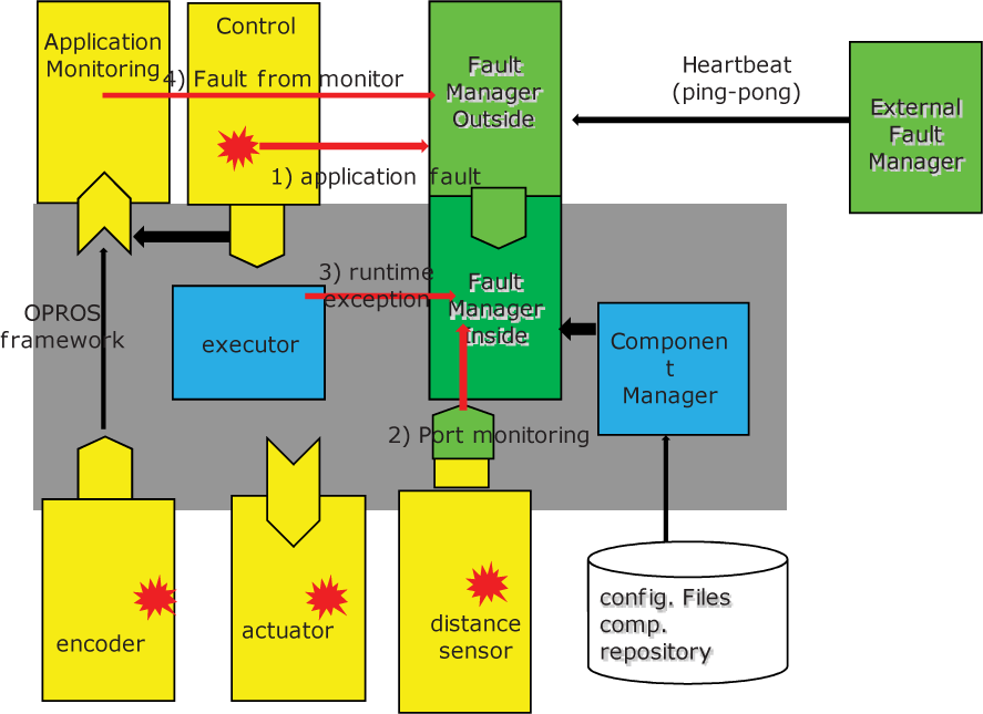
Fault processing flow in the proposed framework
2.3 The Fault-tolerant Techniques Employed
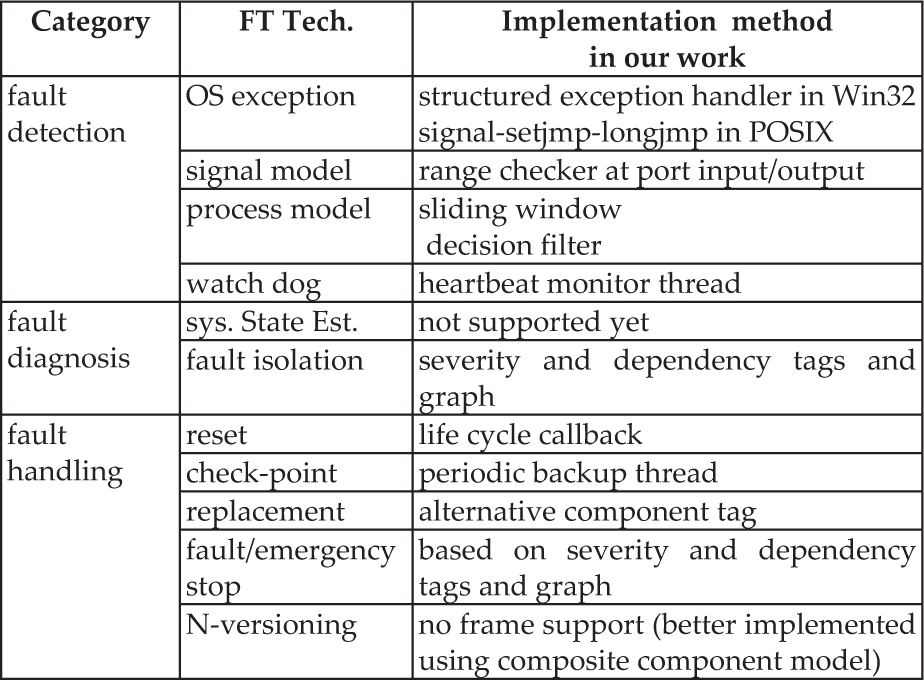
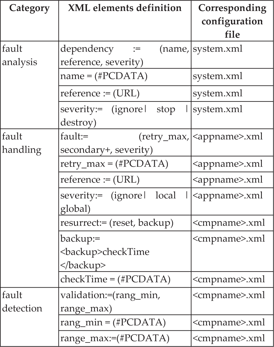
We try to encompass most well-known fault tolerance techniques both in the computer and in the control engineering literature [13, 14] and cover previously known robot system faults [15]. Table 1 summarizes the fault-tolerant techniques employed in our fault-tolerant framework extension in three stages: fault detection, fault diagnosis and fault handling. Table 2 shows the corresponding fault-tolerant XML elements in our system, which extends the original OPRoS configuration file schemas.
Fault tolerance technologies employed in our implementation
Fault-tolerant-related XML elements system configuration XML files
3. Implementation Details and Test Scenarios
This section describes the details of the fault-tolerant frameworks with simulated fault examples. On top of the components and application configuration in 3.1, fault tolerance tools and configurations are added, and then various possible faults are intentionally injected.
3.1 Test Scenarios
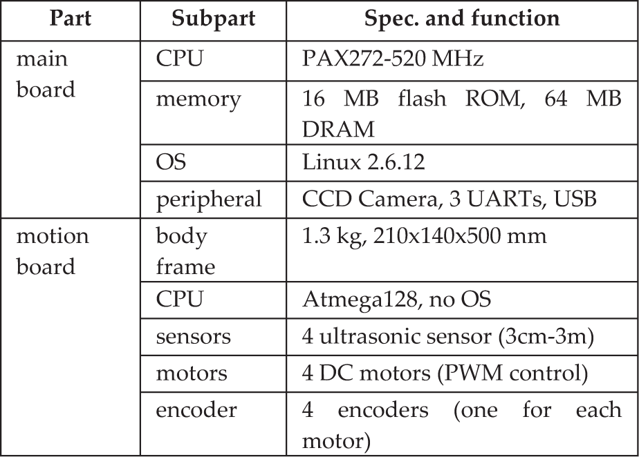
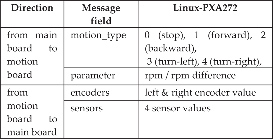
Since desktop Windows, Linux, and embedded Linux systems are the most widely used systems, various tests with the fault-tolerant framework have been performed on all three types of operating environments. In particular, to learn from a realistic robot operating environment and fault scenarios, we implemented a typical embedded robot system. Table 3 is the summary of the system specifications. The main board runs the OPRoS framework and controls the motion board. The AVR microprocessor on the motion board controls four DC-motored wheels and checks the ultrasonic and encoder sensors. A control protocol from the main board to the motion board is defined in Table 4.
Test robot system specification
Protocol between main and motion board
The main test application scenario is a navigation task essential for mobile service robots. The application consists of two independent sub-tasks, path planning and obstacle avoidance (Fig. 6). The colour object detection algorithm is based on the algorithm used for the robot soccer world-cup [16]. The path-planning task consists of one vision sensor component, one object detector component, one path-planning algorithm component and one actuator control component. The path-planning component receives the obstacle location from the obstacle-avoidance task and obtains the target location information its own way, then builds a moving path for the target. Finally, the motion decision made at the path-planning component is sent to the actuator component for the DC motor control.

Test operating application scenario: target following with obstacle avoidance
For the obstacle avoidance subtask, periodically captured ultrasonic data are filtered at the obstacle avoidance component. The final obstacle information is sent to the path-planning component. The obstacle avoidance task uses two different obstacle avoidance algorithm components, one for primary and the other for secondary backup. When there are no faults, the robot reaches the target, avoiding a collision with the obstacles. The system operation in normal and representative fault tests can be watched on the YouTube website (Fig. 7).
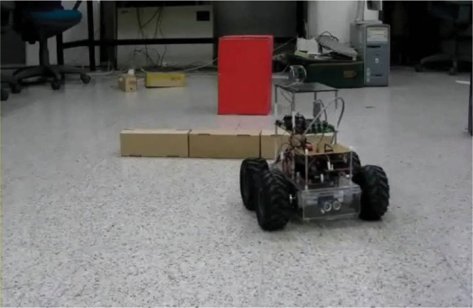
Test robot in action 2
3.2 Fault Detection
Fault detection is usually the most difficult and important step in fault processing. We integrated the following fault detection mechanisms into the OPRoS framework. As will be described in this subsection, the executors, ports and monitor components perform fault detections. On the fault detection, the fault events are reported to the fault manager through fault events or an internal fault manager interface function.
3.2.1 Runtime Software Exception Detection
Lee [17] reports an intensive experimental result on software errors and their propagation patterns. Most runtime software exceptions, such as a segment fault divided by zero, are caused by coding bugs. Furthermore, the most frequent sources of runtime errors are memory access errors, so-called pointer errors, such as dereferencing errors from invalid pointer variables, buffer bound overflow and memory leaks. Most memory faults start with un-initialized pointer and index overflows.
The exception handling methods in modern operating systems can detect many runtime exceptions. Specifically, we implemented ‘sigsetjmp()’ and ‘longjmp()’ on a POSIX system [18] and SHE (structural exception handling), i.e., ‘__try &__except’ on a Microsoft Windows system [19]. First, the exception handler is set up with a stack frame reserved before calling the component callback function. When a runtime exception occurs, the program control flow jumps to the exception handler. Finally, the exception is reported to the fault manager. No XML extension is defined for runtime exceptions at present, because classification and custom handling is not yet considered.
3.2.2 Signal Model-Based Fault Detection
In signal model-based fault detection, the component developers or integrators provide rules for checking the validity of the input and output values of ports. The range is described using the XML tag <validity>, which has sub-elements of <min> and <max>. Then, the connection ports or monitoring helper components (see Fig. 4 (a)) are set up by the fault manager at the port connection time and monitor the data passed through the ports. Broken hardware and short/open circuits are known as the most frequent faults. Though logical errors cannot be detected easily without knowing the logic inside the components, it is possible to check the range of values and parameter type/number mismatch.
The signal model-based technique is used to detect errors in the ultrasonic sensors in the test system. With the fact that the valid output range of the sensor is from 3 cm to 3 m (even though the object is at infinity), unplugging the sensor from the socket (broken sensor emulation) results in output value ‘0’. With the configuration of ‘min = 3’ cm and ‘max = 3000’ cm, the port immediately detected the fault. As for Input port, the input value validation can be often used for protecting its component from outputs from faulty or mismatched/incompatible component connection.
3.2.3 Process Model-Based Fault Detection
A process model-based technique [14] uses models of the system components and plant (such as environments), and then compares the simulation results with the measured values. When the difference is larger than a certain threshold, it is considered to be a fault. Generally, the model can be very complex, dynamic and even stochastic, so applying a process model requires detailed information about the component, sophisticated system identification and an intelligent decision algorithm. We can also develop a fully comprehensive process model for the proposed architecture. Instead, a simplified but still powerful approach is integrated, which is illustrated in Fig. 4 (c). A reference model component is added for one or a sequence of components. The same input data is provided to the target component and reference model component, and the output is directed to the fault manager. There, the filtered outputs with sliding windows period ‘T’ are compared. When the difference of filtered outputs becomes bigger than a threshold ‘D’, the fault event is sent to the fault manager.
3.2.4 Voting Method
The ‘voting’ mechanism or ‘multiple versioning’ is probably the only mechanism for fault tolerance when we do not have either a system or a signal model for a component. The voting mechanism combines a fault detection and a fault handling procedure in one step. Three sonar sensors can be used for sensing the distance from obstacles. A fault-tolerant composite component is composed of a voting component and the sensor components (Fig. 4 (b)). The voting component can select a median value from three inputs or apply a more intelligent filter to the inputs. When a fault is detected from a component, the voting component sends a fault event to the fault manager.
3.3 Fault Effect Analysis and Fault Isolation
All the detected faults discussed above are transferred to the fault manager. We should understand the properties, importance and influence of a component and its faults. Based on the fault severity level <severity> (‘ignore’, ‘reset’, ‘stop’, ‘emergency’) in the configuration file, different fault handling is performed. The coverage of faults is also categorized into component, executor (thread or task) and system level using the <dependency> tag. This is how the proposed mechanism provides fault-isolation and containment checking.
A fault in one component needs to stop the relevant application. A fault in one application requires other applications depending upon the fault application to stop too. The dependency graph model in [20] was adopted for a solution method. We define and express this dependency with <dependency> tags in the system profile and application profiles. For simplicity, we assume that the components and application do not have circular dependency. Fig. 8 is an extension application configuration of our prototype robot system, adding HRI applications. There are three kinds of components with component duplication. Red components are faulty. Therefore, application A (e.g., HRI task) can run in spite of two faulty components in type B (e.g., Camera sensors), but application B (e.g., Obstacle Detection task) should stop operating on the invalid inputs from faulty components. Again, application D (e.g., Human Interaction task), dependent upon the service of application A (e.g., HRI), can run, while application C (e.g., Navigation task), dependent upon application B (e.g., Obstacle Detection task), should stop for the safety of the robot itself and the humans around it.
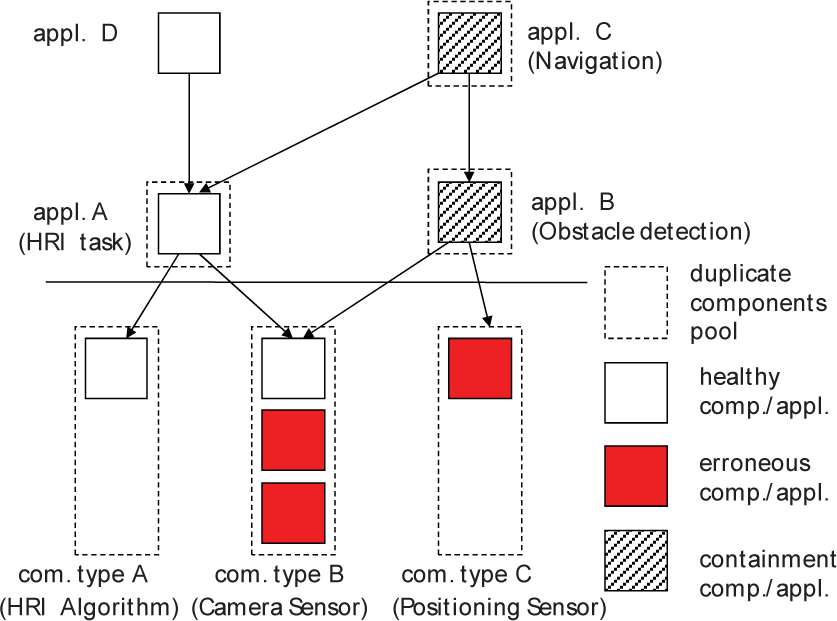
Component dependency graph for fault contamination check
3.4 Fault Handling
Based on the fault diagnosis, fault handling is carried out in three different ways. To aid understanding of the OPRoS system operation and general fault handling procedure, Fig. 9 illustrates three representative fault handling scenarios.
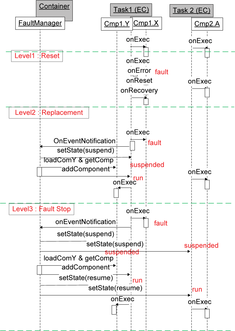
Example method call flows for three different fault handling cases
Fault-Recovery (self-healing): whenever possible, the recovery of a fault component should be accomplished fast enough for real-time operation. The component recovery mechanism has two types, component resurrection and component replacement, which are briefly detailed below. Fault-Stop: when a fault cannot be recovered, the relevant components in the system should also be checked, so that the fault containment region is minimized. When the application (or whole system) corresponding to the faulty components (or application) can run without them, the application (or system) has to keep running. Fault-Safe: when a faulty component cannot be recovered and the corresponding application keeps running, the system may harm people or their environment, so the system must perform an emergency stop to prevent such effects.
3.4.1 Component Resurrection (Reset)
Component Resurrection is a technique that recovers and reuses the fault component. Most stateless components and often even some stateful components in robot applications can be resurrected by reset. Three callback functions, onError(), onReset(), onRecover(), are called when an error occurs and the platform tries to reset the faulty component and then the component is recovered. However, some stateful components do need state-recovery. A check-pointing mechanism is implemented in the OPRoS framework. To simplify the implementation, we add the constraint that a component should save all the state variable in a consecutive memory area and register this address to the fault manager by calling the framework service function, called ‘critical (void *addr, int len)’, where the first input argument ‘addr’ is the address for memory backup, and the second input argument ‘len’ means the size of the memory buffer. The periodic backup and recovery of faults is carried out by the framework automatically. After resurrection of the corresponding component, by calling onRecover the backed-up state is recovered to the component variable.
3.4.2 Component Replacement
The so-called ‘recovery block’ component replacement technique is the most important fault-tolerant tool. When the executor detects that the fault cannot be overcome by reset and that the relevant component is necessary for the task level, this is reported to the fault manager. The fault manager checks the application configuration file to determine whether a secondary component has been prepared by the integrator. When it finds an alternative component, the fault manager loads its dynamic library and passes the component to the executor for replacement. The reset, checkpoint and component replacement techniques are tested and verified using simulated obstacle detection component errors.
3.4.3 Emergency Stop
Because the robot is a mechanical system, the fault isolation and fault stop cannot guarantee fault safety. For example, the faults at a sensor can stop the navigation component, but the robot may still be moving according to a previous command. These risks are well pointed out in ISO safety standards [9]. We break our rule that the framework should not know the specific application of components in order to adhere to these standards. The fault manager takes special care for the actuator components. When the monitor components of the encoder and sensors report a fault to the fault manager, the manager sends a special fault event, the ‘emergency stop’, to the actuator. Then the actuator changes its operation mode from ‘normal’ to ‘emergency stop’. The first action of the actuator on the emergency stop is to place the motors into a safe condition, i.e., ‘stop in neutral’.
3.5 Comparison with the related technology
The AIST team proposed OpenRTM-Erlang [21], which is a reliability-enhanced version of the original OpenRTM-aist. The OpenRTM-Erlang presents a framework coordinating component networks using the concurrent Erlang-language and CORBA introspection interface. The status of components is monitored by callback though the introspection interface API. The developer can and should write their own coordinators to be reactive to the changing state of the robot software system. The callback is implemented in each component node, port and execution context. The coordinator can reconstruct a component network.
We believe that OpenRTM-Erlang project represents more evidence for the urgent requirement for fault tolerance and reliability support in component-based service robot design. While OpenRTM and our proposal share many technical goals and requirements, they are different in architecture level and enabling techniques. OpenRTM-Erlang relies on the CORBA introspection interface for monitoring component and system states, while in our proposal the framework constructs (port, executor, etc.) are equipped with the fault tolerance function and operate based on the XML configuration; the event interface is also utilized for the state information transfer. The Elang language is more flexible to express coordinator behaviour than XML-based input, but it can increase the burden of coordinator design on the developers. In addition, our proposal provides more concrete fault detection methods, while the OpenRTM-Erlang leaves the details to developers by providing the rtctree-erl library.
4. Performance Evaluation
In addition to the functional verification, we measured the fault detection and recovery time to examine time performance.
4.1 Fault Detection Time
In this paper, the fault detection time is defined as the elapsed time from fault manifestation to the instant of detection at the framework or monitor components, excluding the fault dormant time. A comprehensive study could not be performed due to the diversity of faults in robot systems. However, since process-model detection takes longer than the runtime exception and signal boundary fault detection, we show the real-time performance of a motor driver fault. Fig. 10 shows the encoder rpm values when the driver power of the left wheels is switched off at 1000 ms. The encoder value did not drop to 0 due to the physical inertia and the motion of the right wheels. The sliding-windows-filtered output of the monitor component began to generate output values less than the threshold of 0.5 reference value with more than 9 encoder samples, and finally, it was reported as a fault condition 1800 ms later.
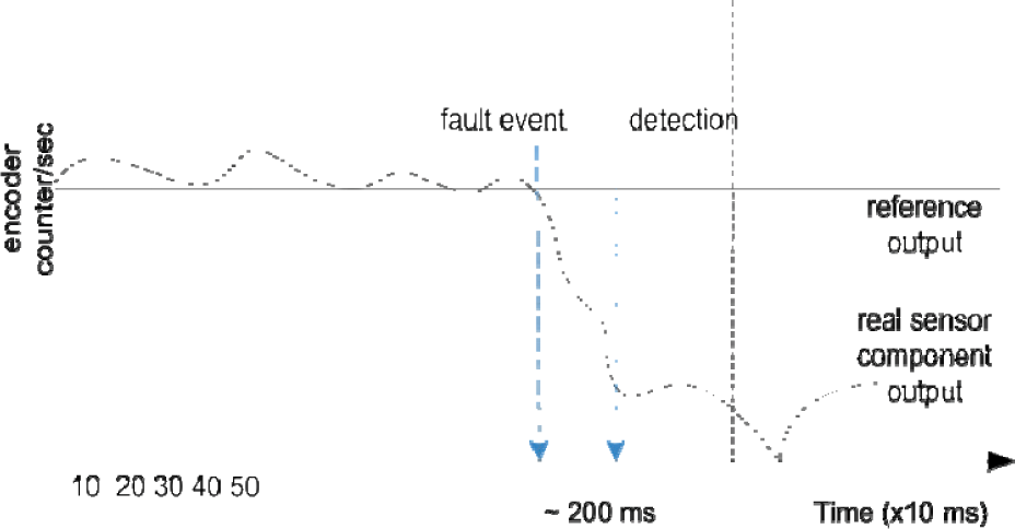
Fault detection delay examination in the proposed framework
4.2 Fault Recovery Time
We also examined the timing aspects of the fault recovery process. In particular, we focused on the time from fault injection to fault recovery. Table 5 summarizes the fault recovery times on three typical operating environments, a desktop Windows, a desktop Linux, and an embedded Linux system. The recovery time can be broken down into the detection, decision, and handling time. With software fault injection examples, the runtime and logical exception handling took a few milliseconds in a moderate system load condition. In contrast, a secondary component replacement procedure often took more than several hundred milliseconds.
Fault recovery time (numbers in parentheses are latencies after the component preloading technique is applied)

The condition is identified as when the load of tasks is over a certain level, i.e., 80% CPU computing power or memory usage. Such a heavily loaded condition is not unusual in an embedded robot system where resources are quite limited. Our analysis revealed that the cause and performance patterns originated from the component loading time. The big difference between the Microsoft Windows system and Linux is in dynamic library size. In the current OPRoS framework, a component DLL file in Windows OS refers to and includes the base class library, the so-called back-reference. Therefore, the component DLL files are much larger than the corresponding Linux dynamic library files. This artefact will be removed in the next OPRoS version.
The difference between a desktop Linux and embedded Linux systems was found to be due to the slow flash ROM. Two methods were considered to overcome this problem. The first solution was to prevent the computation and memory load of the robot system from being overloaded, for example, less than 80% of utilization. The second solution was to use a component pooling/preloading mechanism, which loads the secondary components before a fault occurs. We prefer the pre-loading approach because we do not want to restrict the system utilization for fault tolerance service. With this ‘preloading’ method, we could manage the fault recovery time within 20 ms in any case we tested. The sizable recovery latency observed under the heavy load condition has been resolved using our preloading technique. When the robot is visually examined with fault injections, it continues its motion without any noticeable break.
Even though our design and techniques improved the timing performance, the current version does not guarantee clear performance targets. This can be defined in a parameterized form by robot users, and some real-time enforcement mechanism should be incorporated in the future. For example, fault handling delay should be greater than 200 ms or 400 ms, which is a typical human reaction delay range.
5. Conclusion
The component-based approach is adopted in most recent robot middleware or frameworks to solve the software and system reusability problems. However, most of the proposed component-based robot software platforms have no or very limited support of fault tolerance. In this paper, we presented a fault-tolerant architecture that provides fault tolerance functions at the time of system integration with off-the-shelf non-fault-aware components. In addition to the fault event propagation mechanism, generalized model-based faults are handled automatically in a rule-based manner through the system configuration files. The prototype system demonstrated how well and easily the typical fault tolerance tools can be accommodated. Furthermore, we examined and improved the time performance by the preloading method, although the system cannot yet provide a theoretical timing guarantee. Although the results of this paper are based on a specific middleware framework, OPRoS, the architecture can be applied to other component-based robot systems that have similar basic architecture, especially OpenRTM and MSDS. The main contribution of this paper was to propose the new architecture and show its feasibility and benefits. A comparison study should be performed in the further work.
Footnotes
1
A system component is defined as a special type of component that provides non-application functionality for users.
6. Acknowledgments
This research was supported by the Idustrial Foundation Technology Development Program of MKE/KET, Republic of Korea [No. 10030826]‥