
Abstract
Wall-climbing welding robots (WCWRs) can replace workers in manufacturing and maintaining large unstructured equipment, such as ships. The adhesion mechanism is the key component of WCWRs. As it is directly related to the robot's ability in relation to adsorbing, moving flexibly and obstacle-passing. In this paper, a novel non-contact adjustably magnetic adhesion mechanism is proposed. The magnet suckers are mounted under the robot's axils and the sucker and wall are in non-contact. In order to pass obstacles, the sucker and the wheel unit can be pulled up and pushed down by a lifting mechanism. The magnetic adhesion force can be adjusted by changing the height of the gap between the sucker and the wall by the lifting mechanism. In order to increase the adhesion force, the value of the sucker's magnetic energy density (MED) is maximized by optimizing the magnet sucker's structure parameters with a finite element method. Experiments prove that the magnetic adhesion mechanism has enough adhesion force and that the WCWR can complete wall-climbing work within a large unstructured environment.
Keywords
1. Introduction
With the development of economies and industrial technology, the demand for large unstructured equipment such as ships and oil tankers is increasing. These require that a large amount of welding and inspection work be accomplished in the manufacturing and maintenance of them. Wall-climbing robots can move on a slope and on vertical surfaces and so replace workers in carrying out such work. In view of safety, cost and efficiency, etc., the demand for wall-climbing welding robots (WCWRs) is growing rapidly. During the process of work, WCWRs often need to carry heavy devices and pass obstacles, and so the ability to adhere while moving is crucial. A permanent magnet has the advantage of great adhesion force while not being affected in the case of a power failure. Magnetic wheel-type (Fischer, 2008; Tache et al., 2009) and track-type mechanisms (Kalra and Gu, 2007; Gao et al., 2009) are used in many steel environments. The wheel-type mechanism can move and turn flexibly but the contact surface between the wheels and the wall is small (Fischer, 2010; Tache et al., 2007) and so the energy-use ratio is low; as a result, it is mainly applied by small detection robots. The track-type mechanism has a large contact area (Love, 2007; Yi, 2010) and so the adsorptive force is great and it can move flexibly; however, it is hard to change directions.
To overcome these disadvantages of wheel-type and track-type mechanisms, a non-contact magnetic adhesion mechanism is designed. Magnets are installed under a chassis and there is gap between the magnet and the wall surface so as to adsorb in a non-contact manner. The adsorptive area is big enough to generate great force so that the robot can carry a heavy load. A non-destructive testing (NDT) wheel-type robot is designed in order to inspect a long weld line (Shang, 2008). Magnets are installed under the chassis. The robot consists of a front part and a back part so that it can move on a curved surface. A wheel-type robot for detection and maintenance is also designed by Gui et al. (2006, 2008). These adsorption mechanisms cannot adjust the adsorptive force and so it is hard to use and dismount the robot.
The adjustment of the adsorption force of the magnetic mechanism is realized by either changing the gap or by adjusting the angle between the magnets and the wall. A track-type robot was designed by Xue et al. (2011) to conduct a surface treatment with its magnetic adsorption force being modulated through the former approach. An adjustable magnetic adhesion wall-climbing robot was designed by Wen et al. (2011) with the magnetic adsorption force being modulated through the latter approach. The literature (Wang, 2003) changes adsorption force by means of modulating the total magnetic flow in a closed loop. These mechanisms can only change the force manually, so they cannot realize online automatic adjustment. As a result, the robot's safety and ability to pass obstacles are influenced.
In this paper, the design and optimization of magnetic circuits with finite element methods (FEMs) of a novel non-contact permanent magnetic adhesion mechanism (a magnet sucker) for the WCWR are proposed. The magnet suckers are installed under axles and the gap between the magnets and the wall can be adjusted to change the magnetic adsorption force. The WCWR has a large payload capacity and gives a good performance in passing obstacles. The structure of this paper is as follows: a brief introduction of the WCWR and the magnetic adhesion mechanism is proposed in part 2. An analysis of the balance condition of the wall-climbing process for WCWR and the optimized target for the design of a magnet sucker are presented in part 3. Part 4 proposes an optimal design process for the magnet sucker utilizing FEM approaches. Finally, the effectiveness of this non-contact magnetic adhesion mechanism in improving the robot's payload capability and safety during wall-climbing work is proven by experiments in part 5.
2. Structural design of the WCWR and the non-contact magnetic adhesion mechanism
2.1 Brief introduction of the WCWR's mobile platform
The adhesion mechanism and the locomotion mechanism are key to wall-climbing robots. The structure of large equipment is very complex. In order to meet the demands of welding and maintenance, the WCWR should have a big adhesion force and a good obstacle-passing ability. Furthermore, in order to carry out complicated welding tasks, the WCWR needs a dexterous manipulator with multiple degrees of freedom to hold the torch. To meet these demands, this paper presents a novel design of a wheeled wall-climbing robot (figure 1). The robot comprises a mobile platform, a 5-DOF manipulator and a sensor system. Six wheels and three groups of magnet suckers are mounted under a mobile platform and can be lifted up to pass obstacles. At the same time, the magnetic adhesion force can be regulated to meet the need for locomotion. The detail is introduced in the following parts. Each wheel is independently driven and the difference velocity principle is adopted in order to realize the turn. The robot exhibits good locomotion performance and payload capacity enabling it to move in a big unstructured environment. It can free workers both from carrying out welding work when the welding equipment is installed and from finishing maintenance work when the NDT (non-destructive testing) equipment of other devices is installed.
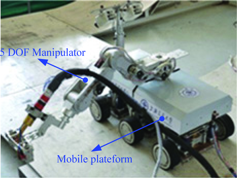
Prototype of the WCWR
The mobile platform is the core of the WCWR and is directly bound up with the robot's performance. The configuration of the platform is shown in figure 2 such that it is composed of three identical groups of wheeled mobile and adhesion parts. Thus, the mobile platform has 9 DC servomotors in total (six for the driving wheels, three for the lifting mechanisms). Each part includes a wheel unit, a permanent magnet sucker and a lifting mechanism. The magnet suckers are mounted under the wheel axels. The lifting mechanism consists of a leadscrew, an actuator with an encoder and some transmission parts. The mobile and adhesion parts can be moved up and down by the lifting mechanism. When the robot confronts an obstacle, the three groups of mobile and adhesion parts are pulled up and pushed down, in turn driven by the lifting mechanisms. It can pass obstacles with dimensions of no more than 70mm *250mm. The process of passing obstacles is presented in figure 3. At the same time, the magnetic force between the magnet sucker and the wall can be adjusted by the lifting mechanism changing the height of the gap.

Model of the mobile platform
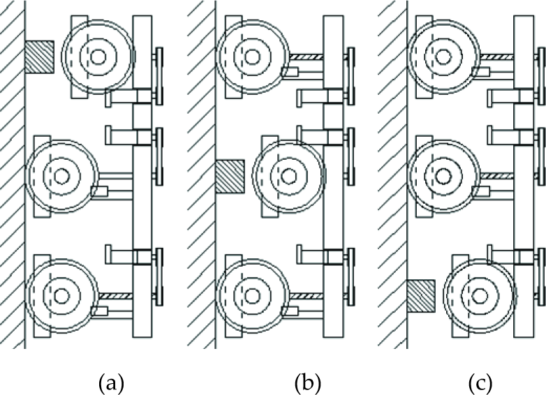
Obstacle-passing process
Each wheel unit includes two independently-driving wheels and an axle. The wheel's diameter is R=133mm and covered with a layer of polyurethane rubber to increase the friction; the driving actuator, which consists of a DC servomotor, a planetary gearbox and an encoder, is installed inside the wheel. The output force of the motor is 78 W and the speed down ratio of the gearbox is 608 (i = 608). The normal output torque and speed after the gearbox are 18 Nm and 9.5 rpm. We can calculate the motion speed of the robot: v = 9.5* pi* R= 4m/min. This speed seems sufficient for the robot to implement welding and other work.
2.2 Design of the lifting and adjustment mechanism for the wheel unit and magnet sucker
During the process of wall-climbing, the WCWR is always required to carry heavy equipment and pass obstacles. It is very important to ensure the robot's safety. Adjusting the adhesion force to meet the requirements of wall-climbing work is a good way to improve the safety of the robot. However, judging from previous studies, most wall-climbing robots do have not both obstacle-passing and magnetic adhesion force adjustment capabilities. A novel mechanism which can pull up and push down the wheel units and the magnet sucker is proposed in this paper, whereby the magnetic adhesion force is adjusted by changing the gap width between the magnet and the wall.
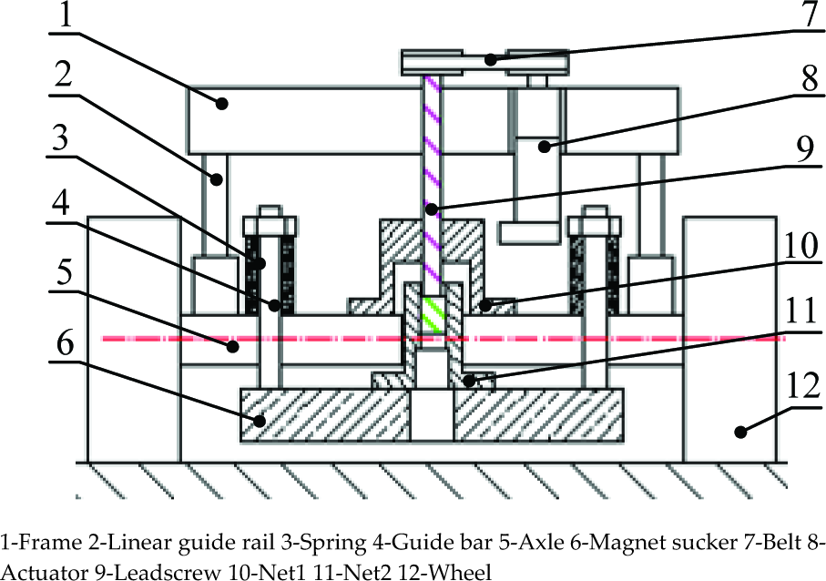
The structure of the lifting and adjustment mechanism is presented in figure 4. It consists of an actuator (with an encoder), a belt, a leadscrew, two linear guide rails and two nuts whose pitches are different. Net1 with 3-mm pitch is mounted on the axle of the wheel unit and Net2 with 5-mm pitch is fixed on the magnet sucker. The leadscrew has two segments of screw whose pitches are 3-mm and 5-mm in order to fit the two nuts, respectively, and forms the kinematic joint. The magnet sucker is installed under the axle by four guide bars and springs -the guide bar and axle forms a sliding pair. When the leadscrew rotates by being driven by the actuator via the belt, the wheel unit and the magnet sucker are moved up or down along the linear guide rail together. Because the pitches of the two nuts are different, there will be relative motion between the magnet sucker and the wheel unit. As a result, the gap between the sucker and the wall, as well as the magnet adhesion force, is changed. The gap is adjusted with a range of 2∼20mm. The gap influences the magnetic force greatly, so the adhesion force can be changed within a large range. Figure 5 shows the operating principle of the lifting and adjustment mechanism. The increase or decrease of the adhesion force is realized by either pushing down (figure 5-b) or pulling up the wheel unit and the magnet sucker (figure 5-a; figure 5-c). Photos of the magnetic adhesion force adjustment are shown as figure 6. Accordingly, the adhesion force can be adjusted in real-time by the actuator under the control of the robot's chief controller. A DC servomotor with a three-stage planetary gearbox (speed down ratio i =84) is selected. The normal output torque and speed are 10 Nm and 69 rpm. The lifting can reach a speed of v = 69rpm * 3mm = 207mm/min.
Structure of the lifting and adjustment mechanism

Operating principle of the lifting and adjustment mechanism
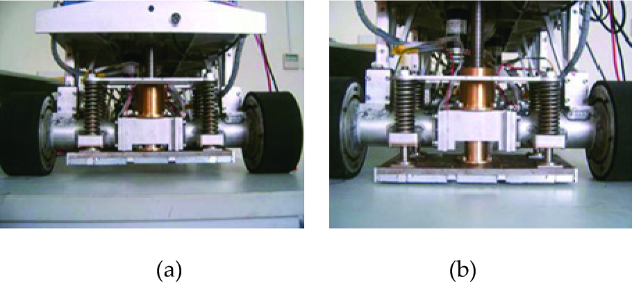
Photos of the magnetic adhesion force adjustment
3. Force analysis and the basic theory of the magnetic force calculation
3.1 Force analysis of the robot wall-climbing process
When the robot is moving on a vertical surface, there may be capsizing or slipping. The robot's safety must be ensured. The adhesion force of a magnet sucker must be strong enough to prevent the robot dropping or slipping from the wall. The analysis of the WCWR's force condition is given in what follows.
There are three cases where the robot might be moving and passing obstacles on a vertical surface, as shown in figure 3. The cases shown in figure 3-a and figure 3-c represent the two most dangerous situations. The robot needs a larger adhesion force than in the situation shown in figure 3-b. The case of figure 3-c is analysed as an example. The forces applied on the robot are shown in figure 7. The main parameters are: robot weight G = 800N; the height of the centre of gravity h = 250mm; the front and middle wheel axis distance L = 260mm; the acceleration less than a=0.5m/s2; the friction coefficient between the wheel and the surface δ = 0.5. F1 and F2 are the adhesion forces, which are produced by the front magnet sucker and the middle one, respectively. Besides this, in order to ensure the robot's safety, the 1.5 times safety factor (s=1.5) is adopted.

Force analysis of the robot on a vertical wall
1. To avoid the robot slipping from the vertical wall, the friction force f which is produced by F1 and F2 must be larger than the total of the robot's weight G and the accelerating force ma:

Generally, the two forces F1 and F2 are equivalent. As such, the result can be attained: F1 ≥ 1260N

2. To avoid capsizing from the vertical wall, the torque induced by F1 should be larger than that induced by G; thus, F1 can be calculated:

In order to avoid capsizing and slipping, the adhesion force produced by each magnet sucker should be greater than 1260N.
3.2 The basic theory of magnetic force calculation
The adsorbing mechanism is the key component of a wall-climbing robot. The performance of the magnet sucker can be improved by optimizing the magnetic circuit of magnet sucker. The analysis and calculation of the electromagnetic field is complicated. The rationale behind the electromagnetic field calculation follows Maxwell's Theory of Electromagnetic Fields. It includes 4 equation sets, such as the Ampere circuit law, three of which are independent. The equation to calculate the electromagnetism using FEM is induced as below:
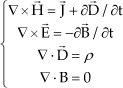
Here, V is a differential operator, H is the magnetic field intensity, J is the current density, D is the electric displacement vector, E is the electric field intensity, ρ is the charge density and B is the magnetic induction intensity. The relationships between the field vectors E, D, B and H in the medium are:

Here, ε is the dielectric constant of the medium σ is the conductivity of the medium and μ is the magnetic permeability of the medium. The magnetic permeability of ferromagnetics such as steel and iron is nonlinear, which decreases as the magnetic field intensity increases.
The magnetic adhesion mechanism is applied in this robot. While the robot is working, the magnetic field generated by the adhesion mechanism is regarded as static. The electromagnetic field generates a unitary magnetic field effect in this situation. The field vectors and source vectors in equation (4) are all space coordinate functions that do not change with respect to time, which can be expressed as:

The field generated by the permanent magnetic adhesion mechanism is a static magnetic field. The double rotation equation of the equivalent vector magnetic potential function is:

The FEM divides the solution area into small areas via the discretization method. Based on the variation principle, the boundary conditions of the differential equation mathematical model can be translated into a variation problem and an extreme-value problem of a function.
The magnetic adhesion mechanism includes many permanent magnets which have a symmetrical structure. In order to reduce the calculated amount in the FEM, the fundamental equation can be induced to solve the Dirichlet boundary value problem of the axial symmetry of the magnetic field:
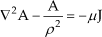
This boundary value problem is:
4. Optimal design of the magnet sucker with the FEM
The magnet sucker consists of permanent magnets, a yoke and an interval. In addition, there is magnetization which is nonlinear with respect to the material and magnetic leakage and the magnetic displacement asymmetry. The sucker's magnetic circuit is complicated and it is difficult to establish an accurate mathematical model and calculate accurately. The finite element method (FEM) is an efficient method to address these complicated calculations. In this paper, the finite element software Ansoft Maxwell V10 is used to optimize the structure parameters of the magnet sucker.
4.1 Optimized target of the magnet sucker
The structure parameters of the magnet sucker are directly related to the sucker's performance. For the wall-climbing robot, it is hoped that the sucker will have a smaller, lighter but bigger adhesion force. The value of the magnetic energy density (MED, the ratio of the adhesion force to the sucker's weight) A directly reflects the sucker's performance. The optimized target is to get as large an adhesion force as possible with the lowest possible weight of the magnet sucker - i.e., to maximize λ. The expression of the ratio is:

Here, Fm is a magnetic adsorptive force generated by the adsorptive unit and Gm is the weight of the magnet sucker.
4.2 Optimal design of the magnet sucker structure with FEM
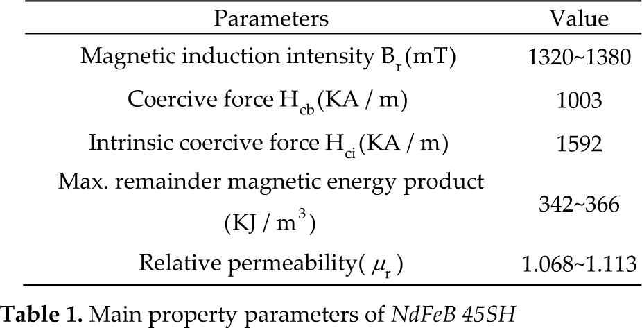
The material of the permanent magnet and yoke directly relate to the magnet sucker's adhesion force and weight. A third generation rare earth permanent magnet material - sintering NdFeB - was chosen as the magnet while the material's mark is NdFeB 45SH. The performance parameters are shown in Table 1. The yoke is made of electrician pure iron - DT4 - which has a high magnetic permeability and magnetic induction.
Main property parameters of NdFeB 45SH
The magnet sucker is comprised of several groups of magnet units. The structure of the magnet unit is shown in figure 8. A magnet unit includes two pieces of permanent magnets and a plate of yoke. The magnets, yoke, steel plate and gap constitute a magnetic circuit. The main parameters are: the thicknesses Hy and the width Wy of the yoke, the thicknesses Hm and the width Wm of the magnet, the height Hg and the width Wg of the gap and the thicknesses Hs of the steel plate (Q235). The permanents are assigned with initial values such that: Hy= Hm= Hg= Hs= Wg=10mm, Wm=25mm, Wy=60mm and the length of the magnet unit is L=100mm. In the simulation experiments, only one parameter is allowed to be changed at each simulation instance. One set of simulation results for the magnetic flux density distribution is shown by figure 9.

Sketch of the magnet unit

Distribution of the magnetic flux density
1. The influence of magnet thickness and yoke thickness
The thicknesses of the magnet and the yoke are chosen as variables so as to analyse their influence on the performance of the adsorptive structure while the other parameters constants. Figure 10 shows the influence of the magnet thickness and the yoke thickness on the MED (λ). When the magnet's thickness is regarded as a constant, the MED would increase greatly at the very beginning with the increase of the yoke's thickness and it would increase with a lower rate when the thickness reached a certain value. However, the force no longer changes and λ begins to decrease instead. The main reason for this is that when the yoke thickness reaches a certain value, the magnetic leak is too small to influence the adhesion. It can be observed from figure 10 that when the magnet thickness is 4mm, 6mm, 8mm, 10mm, 12mm or 15mm, the yoke thickness – in order to maximize the magnetic energy product - is 5mm, 6.5mm, 7.5mm, 8mm, 9mm and 10mm. When the yoke is 9mm thick and the magnet is 12mm thick, the magnetic energy density λ reaches peak-54. As a result, when the gap is fixed, in order to maximize λ the yoke thickness changes according to the magnet thickness. As such, the magnetic displacement of the yoke must be appropriate.

The influence of the thickness of the magnet and the yoke
2. The influence of the magnet width
When other parameters stay the same, increasing the magnet width wp, the magnetic adsorptive force would increase accordingly. The weight of the magnet also increases and the relationship between magnetic energy density and the magnet width is shown in figure 11. As the width increases, λ increases significantly; however, when λ reaches the peak, it decreases instead. When wp increases to 25mm, λ reaches the maximum value.
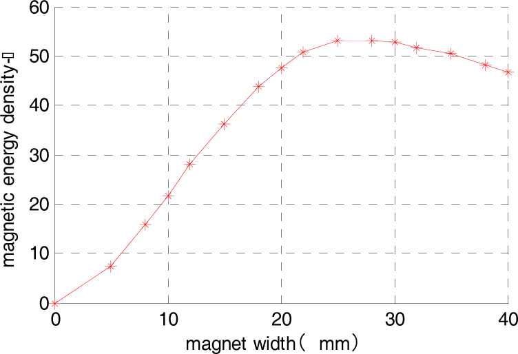
The influence of magnet width
3. The influence of the gap between magnets
When the height of the gap between the magnets increases with other parameters being unchanged, the adsorptive force becomes greater but the yoke width increases; thus, the weight of the whole magnet unit increases. The influence of the gap between the magnets on λ is shown in figure 12. When the gap w is 11mm, λ reaches its maximum value. However, when the gap continues to increase, the adsorptive force will increase slowly while λ will decrease instead.
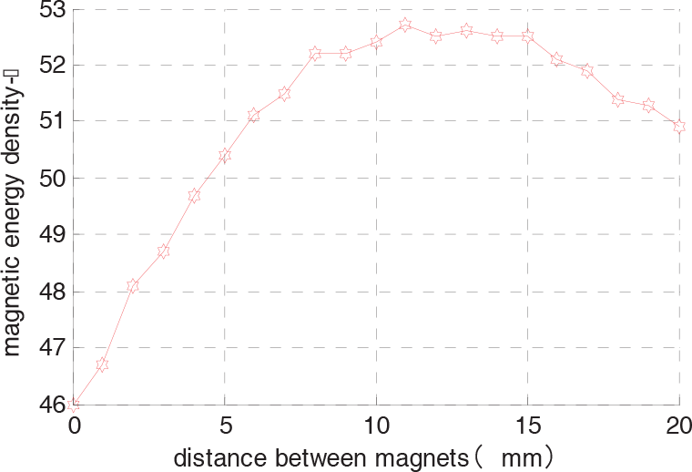
The influence of the gap between of magnets
4.3 Optimization analysis of the magnetic circuit coupling
The influence of the magnetic structure parameters on the performance of the magnet was analysed in the previous paragraphs. The magnet sucker is made of several groups of magnet units and so the coupling between the units influences the performance of the sucker directly. There are three common styles of coupling, as shown in figure 13.

Sketch of the coupling structure
The magnetic poles of the adjacent two magnets are opposite to each other. The yoke thickness is 9mm, and the magnet thickness is 12mm while the gap between magnets is 11mm. The magnets are all 100mm long and couple only in the X direction in structures (a) and (b). In structure (a), each magnet has the same width-25mm and the whole width of the sucker is 133mm. The magnets on the sides of the sucker are 25mm wide in the structure (b), the middle one is 50mm wide and the whole width of the sucker is 122mm. There are couplings in both the X and Y directions in structure (c), where the size of the X direction is the same as that in structure (b) while the magnet in the Y direction is 50mm; thus, the whole length is 111mm.
The results in figure 14 demonstrate that when the gap is shorter than 4mm, structure (b) generates a smaller force than structure (c). However, when the gap is larger than 4mm, structure (b) generates a larger force than structure (c). Under different heights of the gap, structure (b) generates a larger force than structure (a). The force generated by structure (b) has a larger value of MED (A) than that generated by the other two structure styles.
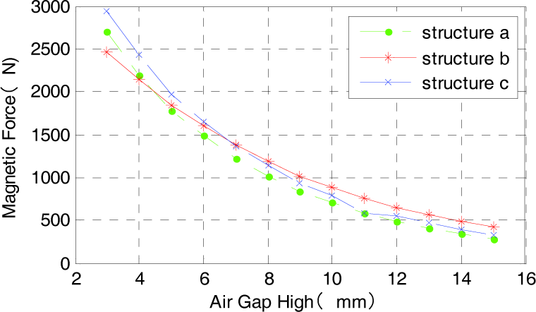
Coupling result
5. Experiments of the magnet sucker and the WCWR
According to the results of the analysis in part 4, the size parameters of the magnet sucker are: yoke thickness-9mm, magnet thickness-12mm, magnet width of two sides-25mm, middle magnet width-50mm, gap between the magnets-11mm, the whole width W = 120mm, the whole length L = 244mm, the size of the whole magnet-244 × 120 × 21mm3, the whole weight of the magnet sucker-Gm = 4.33kg. The magnet sucker is shown by figure 15. There is a hole in the middle for the leadscrew to pass through the magnet sucker when it is pulled up and pushed down.

The object of the magnet sucker
A test device was designed to test the performance of the magnet sucker (Figure 16). The device and the robot's lifting mechanism - which is presented in part 2 -work in much the same way. The magnet sucker can be pulled up and pushed down by an actuator turning the leadscrew through the belt. A force sensor is mounted under the steel plate to measure the sucker's magnetic force. A computer with a data acquisition card is used to deal with the test result. The adhesion force of the magnet sucker was tested for different heights of air gap. The test results are shown in figure 17. When the height of the gap changes from 5mm to 15mm, the adhesion force changes accordingly from about 5,000N to 1,000N. The adhesion force can reach about 2,250N when the gap is high at 10mm. Compared with the analysis results in part 2, the magnet sucker can meet the requirement of security.

Magnetic adhesion force test device; (a) Structure of the test device (b) Experiment of the magnetic force

Test results of the magnet sucker
In order to test the performance of the magnet adhesion mechanism and the WCWR, a simulation platform is designed to perform obstacle-passing and wall-climbing welding experiments. The platform simulates the manufacturing environment of large unstructured equipment (figure 19-a). Experiments are performed on the platform to prove whether the WCWR works well. Figure 18 shows the experiment photographs of passing obstacles - the experiment results show that the lifting mechanism works well and that the robot can overcome a 70mm high obstacle. In the process of passing obstacles, the obstacle-passing sequence is: while the robot is moving on a vertical or horizontal surface and meets a obstacle, the actuator of the front lifting part drives the leadscrew and lifts the front wheel unit and the magnet sucker to a position at a sufficient height; next, the robot moves forward and the first wheel unit passes the obstacle; finally, the front wheel unit is lifted down. The middle and tail wheel units are controlled to pass obstacles in the same way. The adjustment of the magnetic adhesion force is as described earlier in Section 2.2.

Experiment of passing an obstacle

Experiments of wall-climbing work; (a) Experiment on the simulation platform (b) Experiment in the application spot
Figure 19 shows the wall-climbing experiments on both the simulation platform and the workshop. Figure 19-a is the experiment on the simulation platform: the robot started moving from the horizontal surface, turned and climbed onto the vertical wall through the circular arc surface; then, the robot overcame the obstle and climbed down the simulation platform. Meanwhile, experiments of the WCWR carrying a load of 30kg and passing obstacles on the wall have also been carried out. To ensure the robot's safety, a rope is attached to the WCWR. Nevertheless, we performed a further experiment on the application spot for manufacturing a gas tank (figure 19-b). The WCWR can climb on a circular arc tank surface and implement welding. The results of the experiments demonstrate that the magnet sucker gives a good performance and that its adhesion force meets the requirements of the wall-climbing work. The robot possesses good payload ability and can replace workers in carrying out welding work on large unstructured environments.
6. Conclusion
Owing to the fact that the magnet sucker is mounted under the robot chassis and does not make contact with the wall, the WCWR exhibits good payload ability and a small turning resistance, which brings good flexibility. The novel lifting mechanism can lift the wheel unit and magnet sucker together using only a motor. At the same time, the adhesion force of the magnet sucker can be adjusted by adjusting the height of the gap between the sucker and the wall. Thus, the WCWR gives an outstanding performance in terms of safety, its payload and its obstacle-passing capacity.
In our project, the WCWR is intended to be applied in a large unstructured environment, such as with ships. The robot is required to carry cable and other additional pipelines during moving in a large scale. The greater the distance the robot moves, the heavier the load the robot has to carry. To turn the WCWR into a practical application, this is a problem that must be solved. In our next work, we plan to design a wall-climbing robot to carry the cable and other auxiliary equipments - such as electrical force - while the robot moves following the WCWR.
Moreover, it is very important to ensure the robot's safety during the process of wall-climbing work, although the WCWR has a good adsorptive ability. During the experiments, a rope was attached with the robot in order to ensure its safety. It is also a good way to solve the problem in a practical application.
Footnotes
7. Acknowledgments
The support of the National High Technology Research and Development Programme of China, through the Ministry of Science and Technology of China Grant No. 2009AA04Z221, is gratefully acknowledged.