
Abstract
This paper presents two vision-based interfaces for disabled people to command a mobile robot for personal assistance. The developed interfaces can be subdivided according to the algorithm of image processing implemented for the detection and tracking of two different body regions. The first interface detects and tracks movements of the user's head, and these movements are transformed into linear and angular velocities in order to command a mobile robot. The second interface detects and tracks movements of the user's hand, and these movements are similarly transformed. In addition, this paper also presents the control laws for the robot. The experimental results demonstrate good performance and balance between complexity and feasibility for real-time applications.
1. Introduction
In recent years, robotic technologies have been profoundly affected by new knowledge, which has led to expansion in many fields, including industrial and agricultural robotics, space projects and so on. Medical robotics is a promising field with several applications: surgical robots, surgical training, radiotherapy, telemedicine, hospital robots, and rehabilitation or assistive devices [1].
The “rehabilitation robots” or “assistive robots” concept refers to a whole set of technological solutions for handicapped people, or patients with neuromuscular disorders such as cerebral palsy, quadriplegia or multiple sclerosis, among others. These mechatronic devices allow people to increase their autonomy in daily activities, hygiene, and mobility.
Mobile robots or robotic wheelchairs are automatic transportation devices, capable of navigating through a particular environment with some degree of autonomy and performing specific tasks. For this reason they are used as assistive robots, attracting the attention of many research groups around the world. Some authors focus their attention on the human-machine interface, proposing alternatives to the control input such as electromyography (EMG) [2, 3], bioimpedance [4], Brain-Computer Interface (BCI) [5], face detection [6-8], or hybrid approaches [9, 10]. Others propose different control strategies in order to ensure velocity control, safety and robustness. In [2], the user indicates the desired direction with the EMG of an intact muscle, and the speed of the wheelchair is determined by the muscular force estimation. This is similar to [3], in which an EMG human-machine interface is designed to map facial movement patterns into control commands for a wheelchair. A more sophisticated interface is presented by Yunfei et al. [4]. Based on the bioelectrical impedance of the trapezius muscles, it detects the changes in movement of the left and right trapezius muscles, and translates these movements into control inputs. Despite the good results, the use of EMG requires the attachment of electrodes, which can cause discomfort to the user over a day of use.
In the case of BCI, electrodes attached to the scalp or to a skullcap are needed in order to register the electroencephalogram (EEG) signals. These interfaces are a suitable alternative for tetraplegic patients, who may control an assistive device by imagining movements [5].
Vision-based Interfaces (VBIs) represent a completely non-invasive method to detect the pose of the head, hand or markers, and use it as a control input to some device. This approach is widely used [6-8] due to its instrumentation simplicity, its low cost and its non-invasive nature.
However, in any of these interfaces, it is necessary to define a control strategy that ensures the complete control of the velocity, acceleration and stability of the wheelchair. For example, in [11], the authors propose a human-robot integration as a mechanism to augment or improve robot autonomy in daily scenarios. In [12], an agent-based controller is used to command an autonomous robotic wheelchair in indoor environments. The navigation system of the autonomous robotic wheelchair is developed as a group of intelligent agents, including the robotic wheelchair, the path planner, the fuzzy logic-based motion control and the obstacle avoidance strategy. Although this is an excellent approach, [12] only presents simulated results. A more complete interface for cognitively disabled children is presented in [13]. Three different interfaces are provided: one based on speech recognition, a motion interpreter, and one based on visual feedback. The results are very promising, since the children were able to guide the wheelchair from the first time. However, the disadvantage of this work is that it does not provide a control system which ensures that the wheelchair achieves the desired velocity. Furthermore, this system is not suitable for patients with severe brain and spinal injuries who do not have recognizable speech and haptic sensing abilities. The already-cited interface based on head gestures [8] integrates the Adaboost face detection algorithm and Camshift object tracking algorithm. The control architecture has two control modes: intelligent control and manual control.
In this paper we propose two VBIs, specially designed for individuals with severe motor disabilities, to command a mobile robot for personal assistance. One of the main goals of this work is to provide a free and open source algorithm of image processing and control, suitable to be used in any standard personal computer without any additional commercial device. The VBI herein proposed is a low cost system that only needs a webcam. Head or hand movements are detected and the choice of one of them is determined by the residual capabilities of each user, which are prompted to guide the mobile robot. The control algorithms are based in the kinematic model of the robotic system in order to regulate its linear and angular velocities. This way, the navigation results are more secure for users because the VBI is included in a complete assistance system
2. Vision-based Interfaces
This paper presents two vision-based interfaces (VBIs), which will be described in the following sections. VBIs are perceptive interfaces that use image processing techniques to extract the parameters of interest. A block diagram of the interface developed is shown in Figure 1. First, a webcam captures the image of the hand, foot or head of the user; then, the image passes through the module of image processing where different algorithms extract the parameters of interest. Once these parameters are extracted, they are translated into commands by the control module, reflecting the user intentionality. Finally, these commands are used to carry out some task in assistive devices.

Block diagram of the VBI
The main advantage of VBIs is that they are non-invasive and, in particular, the interfaces developed in this work are low cost and feasible, because they are composed by only one standard computer and the webcam. In what follows we will describe the developed interfaces classified according to the image processing algorithm implemented for detection and tracking.
2.1 Vision-based interface for estimated head pose
The interface developed uses the artificial vision as a communication medium from the user to the computer. A webcam captures images of the user's head and, through an image processing algorithm, the presence of the face and its orientation are detected. This information is used for obtaining the reference angles in order to generate the input commands for a mobile robot. The posture of the head is obtained by using the optical flow technique. This technique is selected since it has a lower computing cost, and the calculus of the parameters with optical flow does not fail if the illumination changes or if there are broad head movements, because the calculation of optical flow does not depend on the geometric points in the space.
The projection of the 3D movement of a rigid object generates a movement field on the image. This movement field on the image is defined by a 2D temporal function which relates the relative spatial variation between the view camera and the observed scene [13]. The equations of the movement field can be obtained by projecting the mobile point in the 3D space onto the image plane. For this projection, the origin is located at the optical centre of the camera and the X and Y axes are defined in such a way that they form a basis for the image plane. The Z axis is the same as the optical axis of the camera. This situation is described in Figure 2.

Coordinate system
Let
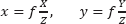
where f is the focal length. The relative movement between the point
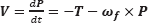
where T = [Tx Ty Tz]
T
is the translational component and ω
f
= [ωx ωy ωz]
T
is the rotational component. Since the movement corresponds to a rigid object,
Thus, the movement field

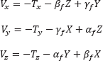
where Vx, Vy, Vz are the components of V defined in Eq. (2). Introducing Eq. (2) into Eq. (3), we obtain the following matrix equation:

In Eq. (4) two terms can be distinguished: the first describes the component of the movement field of the image due to the object's translation, which is inversely proportional to the depth in each point. The second term is the component of the movement field of the image due to the rotation of the object, which is independent of the depth. Once the relation between the three-dimensional space and its projection on the image plane is obtained, we apply the concept of optical flow.
The optical flow, or image speed, is the bidimensional field of apparent speed in the image plane associated with the variation of patterns of brightness intensity in an image. This field can be produced due to the movement of the observer, the movement of the objects in the scene or the apparent movements.
The values of optical flow
Defining

Applying partial derivatives we obtain:
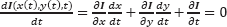
Partial space derivatives of the brightness intensity of the image represent the space gradient of the image, ▽I, and the time derivatives,

Analysing Eq. (7) it can be noted that there are two unknown parameters, (u,v), but only one equation for each point of the image. Therefore, we can determine only the speed component in the direction of the brightness gradient.
In order to calculate the values of (u,v), firstly it is necessary to obtain the feature points. The chosen feature points do not belong to any geometric organization of the face represented in the image. Based in the high magnitude of the gradient vector in the corners, they were selected as estimators of the flow vector.
The next step is the identification of the corner points in the contour by using a method based on the spatial gradient of the image [13]. With this aim, let us consider an image point p, a region

where Eix and Eiy are the components of the gradient for each point in the region

where λ1 and λ2 are the eigenvalues of the matrix
A corner is the result of two contours with high gradients. Therefore, the eigenvalues of matrix
The selection of the threshold and the size of region
Point features
With n calculated feature points, the values of optical flow are obtained by implementing the method described in [14]. This method uses the Kalman filter to accomplish a data fusion step, obtaining a robust optical flow, which is shown in Figure 4. The estimation is carried out between two successive frames, It and It+1.

Optical flow
It is important to remark that any other technique, such as the classic Haar technique, can be used for obtaining the image features before the calculus of the optical flow. Nevertheless, it is considered that those techniques which detect facial features, like eyes, mouth or nose, detract from the robustness of the system. This is because these techniques fail when some facial feature cannot be detected.
2.1.1 Estimation of the head movement
An estimation of the 3D movement is obtained by calculating the parameters of the successive rotation and translation between two frames, using the movement field in 2D. In this section we will explain the extraction of the parameters of the head pose from the optical flow.
The projection of the movement in 3D into the 2D movement field is given by Eq. (11). It is assumed that there is a movement of the head in the image (and all the background remains static), and the movement of the rigid body between two frames is infinitesimal. Therefore, the angular velocities can be directly replaced by the values of the angles. The variation of the angles cannot be higher than 5°, in accordance with [15]. This assumption does not represent an important restriction since the webcam used in this work needs only 100 ms to process two frames, which is a very short time to make big head movements.
Equation (2) can be rewritten as follows:
where α f is the rotation angle related to the X axis; β f is the rotation angle related to the Y axis, and γ f is the rotation angle related to the Z axis. Subscript f refers to the variables obtained by the optical flow technique.
If

The system of Eq. (11) is solved by using recursive least mean square, minimizing the error:

where

This way, the three orientation angles of the head in the 3D space are obtained. However, only the angles βf and αf are used to command the mobile robot. The angle βf is the reference angle of the rotation for the mobile robot and the linear velocity is activated by angle αf.
2.1.2 Preliminary experiments
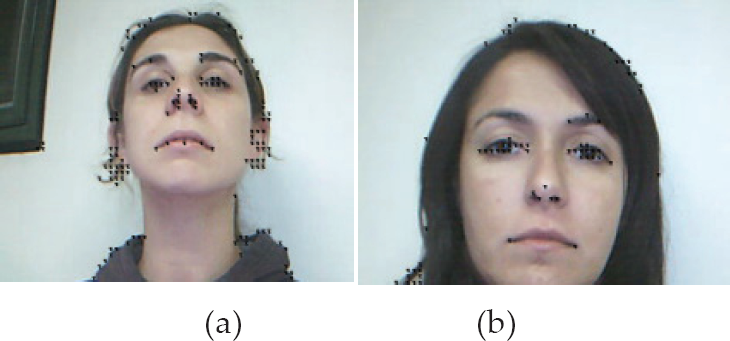
The experiments of this interface were performed with real image sequences captured at 10 frames per second with a webcam. The size of the image is 320×240pixels. The optical flow estimation from the image sequence (a) is shown in Figure 5. In Figure 6, we present the evolution of α, β and γ, corresponding to the image sequence of the face (a). Similarly, Figure 7 shows the optical flow estimate from the image sequence (b) and Figure 8 depicts the evolution of α, β and γ, corresponding to the image sequence of the face (b).

Image sequence (a)

3D rotation parameter estimation results for the image sequence (a)

Image sequence (b)

3D rotation parameter estimation results for the image sequence (b)
2.2 Visual-based Interface for estimated hand pose
The interface described in this section uses the image of the user's hand, captured through a webcam. The image processing algorithm detects the presence and orientation of the hand, and uses this information in order to obtain the reference angles for generating the input commands for a mobile robot.
The first step is the image segmentation for detecting the hand in the image plane captured by the camera. This task is performed in the HSI colour space (Hue-Saturation-Intensity) because the skin colour is grouped in a precise region of this colour space [18–20]. With this transformation a binary image is obtained, in which the white colour represents the detected skin (Figure 10 and Figure 11).
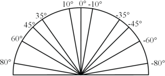
Graduated pattern used to determine the real orientation of the hand.

Original image captured by the interface and processed image with the major and minor axes detected (hand in position with palm down)

Original image captured by the interface and processed image with the major and minor axes detected (hand in side position)
The binary image, obtained through the segmentation process, is necessary to determine the characteristics that represent the position and orientation of the hand. The characteristics chosen are the coordinates of the centre of mass and the orientation angle and the axes (minor and major) of the hand. The centre of mass and the axes are calculated by using the moments of the image. If we define I(x,y) as the intensity of the image in the position (x,y), the following expression defines the different moments:

with i,j = 0,1,2.
The coordinates of the centre of mass is calculated as:
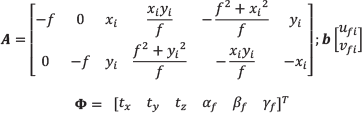
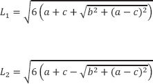
Then, the hand is considered as a rectangle and the major axis L1 and the minor axis L2 are computed as:
In order to obtain the hand orientation, the Principal Components Analysis (PCA) tool is used [13]. The binary image previously obtained is considered as a two-dimensional population, i.e., each pixel of the hand is treated as a two-dimensional vector

where n is the number of vectors obtained in the binary image. Then, a covariance matrix is calculated:

Once
The angle obtained is the reference angle for the rotation of the mobile robot.
On the other hand, to activate the linear velocity the value of the minor axis L2, defined in Eq. (14), is used. A threshold value for minor axis Lmin = 70 pixels is established such that:
If L2 > Lmin, the hand is extended with the palm down (Figure 9) and the robot must stop.
If L2 < Lmin, the hand is in a side position (Figure 10) and the robot must move.
This threshold value is determined experimentally.
2.2.1 Preliminary experiments
The first step of the evaluation of the performance of the measurement system is to obtain the orientation angles of the hand in static positions. The real orientation of the hand for each measurement is obtained by using a graduated semi-circular pattern (Figure 9) where the user's hand leans.
An example of the captured image of the hand with the palm down and the image obtained after the image processing is depicted in Figure 10. This figure also shows the major and the minor axes located at the hand's centre of mass. The angles estimated are compared with the real angles, and the measurement errors for this position of the hand are less than |5,5°| (Figure 12).

Comparison between real orientation angles and estimated angles. Circles: real orientation; Squares: estimated angles with the hand with the palm down; Stars: estimated angles with the hand in side position

Geometric description of the kinematic model of the unicycle-like robot
The result of the image processing for the hand in the side position with the image's characteristics is shown in Figure 11. In this case, the comparison of the estimated angles with the real angles presents errors below |3,6°| (Figure 12).
The detection of the position of the hand (with the palm down or in side position) is carried out correctly in 100% of cases.
3. Mobile Robot
3.1 Model of the Mobile Robot
The set of equations that describe the kinematics of the unicycle-like robot are:

where (xr,yr) are the cartesian coordinates of the robot in a global framework; φ is the heading of the robot; and
The non-holonomic constraint for the kinematic model (previously defined in Eq. 17) is:

3.2 Design of the Controller
Control law for the angular velocity: the proposed non-linear control law for the angular velocity is

where kω is a positive design gain and
Control law for the linear velocity: in order to achieve a smooth navigation, it is necessary that the robot can change its linear velocity vref as a function of the orientation error

Similarly, the proposed control law for the hand interface described in Section 2.2 is:

Vmax must be defined while taking into account both the physical limits of the robot and the capability of the user to guide the robot at a determined velocity.
4. Experimental results
This section presents the experimental results with both systems, i.e., with both vision-based interfaces, which were evaluated with four individuals with severe motor disabilities. First of all, the users or their parents (in the case of underage users) gave their informed written consent to the experiment. Then, the volunteers carried out a proposed task with a mobile robot. Briefly, we will describe their pathologies. Individual A is a fourteen-year-old boy who has cerebral palsy. Individual B is an eight-year-old girl suffering motor anomalies due to a tumour. Individual C is an eleven-year-old boy with Duchenne muscular dystrophy. Individual D is a thirty-five-year-old woman who has quadriplegia.
The performance evaluation of the proposed systems is based in the HAAT model (Human Activity Assistive Technology) [17]. According to this model, the system is not composed only of the assistance device, but also includes the user, the activity carried out by user and the context where the activity will be developed. Therefore, the system is effective if it is useful to the user for achieving the objectives of the proposed activity.
In order to evaluate the performance of the interfaces and the controller, a mobile robot Pioneer 2DX is used in a real environment. The objective proposed for this activity is for the user to guide the robot through different corridors. The user has to manoeuvre the robot to navigate from one corridor to another. With this aim, the robot should move to the left or to the right. The constants are set as:
To demonstrate the feasibility of the system, the camera used for obtaining the images is a standard webcam and the experiments are carried out in a real environment without illumination control. The environment selected represents medium difficulty for the user, because it requires the user to guide the robot to turn right or left without obstacles in its path. Although the inclusion of obstacles could be interesting for the system evaluation, it was decided to relax the difficulty since these experiments represent the first experiences of the users with the new technology.
Once the objective of the activity is defined, six experiments are carried out by each user: three with the VBI described in Section 2.1 (head interface) and three with the VBI described in Section 2.2 (hand interface). For each user, a table (see Table 1) is made. In this table is registered whether or not the user attains (denoted by ✓) or does not attain (denoted by ×) the objective proposed.
Results of the experiments with the vision-based interface and the mobile robot. VBI 1 corresponds to the interface described in Section 2.1 and VBI 2 to the interface described in Section 2.2.

Note*: Experiments with the individual B when using VBI 2 correspond to the 3°, 4° and 5° intent; this user needed to carry out five experiments with VBI 2.
After finalizing the experiments, each user answers a questionnaire about his or her feelings and personal experiences with the assistive system.
By way of example, one experiment using the head interface (Section 2.1) and another using the hand interface (Section 2.2) are shown.
Figures 14 to 16 correspond to the first experiment (head interface) of volunteer C. Figure 14 shows the angular reference obtained from the head movements, while Figure 15 present the evolution of the linear and angular velocities of the mobile robot. Finally, Figure 16 shows the trajectory described by the robot in the corridor.
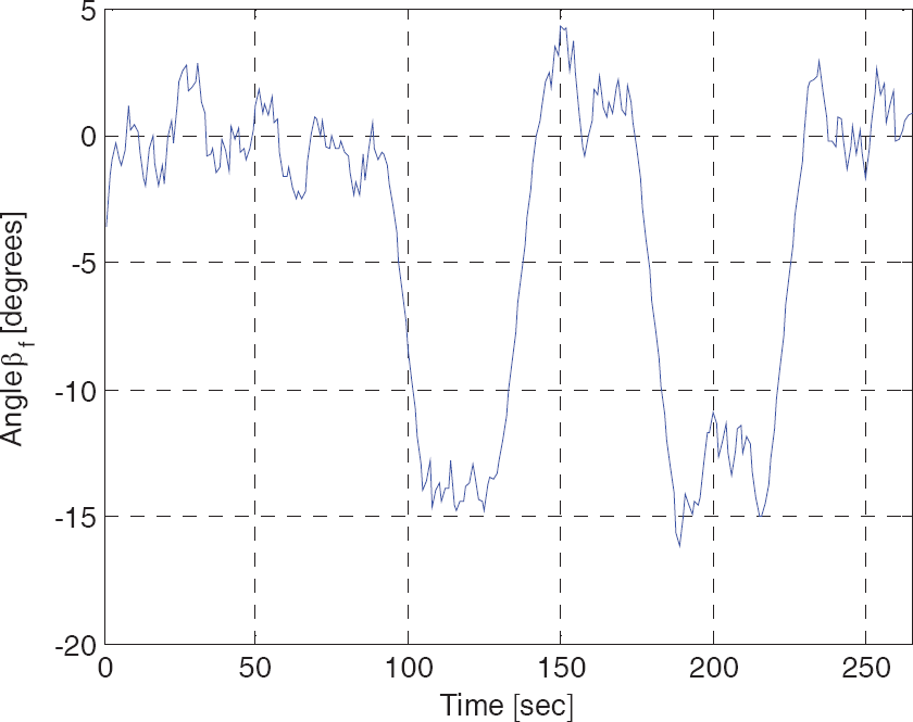
Evolution of the reference angles sent by the interface to the robot
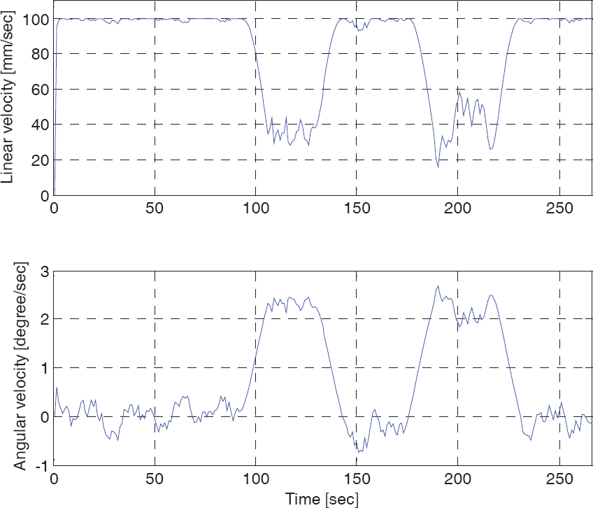
Evolution of the linear and angular velocities of the mobile robot

Trajectory described by the mobile robot in the real environment
Figures 17 to 19 correspond to the fourth experiment (hand interface) with individual C. Figure 17 shows the angular reference obtained from the hand movements and the angle effectively turned by the robot to reach the reference. Figure 18 presents the evolution of the linear and angular velocities of the mobile robot, and Figure 19 presents the trajectory described by the robot in the corridor.

Evolution of the reference angles sent from interface to robot (dash line) and evolution of the robot's orientation angle (continuous line)

Evolution of the linear and angular velocities of the mobile robot

Trajectory described by mobile robot in the real environment
In the analysis of the results, we can note that all users were able to complete two of the three experiments carried out with VBI 1 and three of the four users were able to complete two of the three experiments carried out with VBI 2. Therefore, it can be concluded that the interfaces are simple to use, giving the volunteers a real possibility to guide an assistance robot.
It is worth noting that in rehabilitation engineering, assistive technologies cannot be standard devices. The number of people who have exactly the same need, and for whom the same device will be appropriate, is small. Therefore, in spite of having only four volunteers, we consider that the results obtained are positive, since all of them, with their different severe motor disabilities, achieved the proposed objectives.
5. Conclusions
In this paper, a complete approach to the control of mobile robots is proposed, based on two different VBIs. It is important to note that the system presented is a low-cost interface that can be implemented in any standard computer with a webcam.
Due to the variability in residual movements in individuals with several motor disorders, both facial image information and hand movements were processed and translated into control inputs; the choice between these is determined by the user's needs.
The experiments are carried out by implementing the designed control system in a real environment with the four disabled volunteers described. A complete evaluation of the controllability of the mobile robot was presented in the preceding section, and the results show that the users perform the task proposed without difficulties, even in the first trial. The interaction between the robot and the users through the VBI was easy and intuitive, and the interface represents a suitable alternative for commanding assistive robots such as wheelchairs.
Moreover, the control law shows good performance and feasibility in translating the posture of a user's hand or head into velocity commands in order to achieve safety navigation.
Footnotes
6. Acknowledgment
The authors thank the National Council of Scientific Research of Argentina (CONICET) for partial support of this research.