
Abstract
In the case of operating a vehicle, if the interface extracts human intention correctly and naturally, and if the vehicle moves like a human, then the human feels this operation to be intuitive. For realizing intuitive operation, this paper proposes motion design which makes vehicle motion anthropomorphic. The strategy of this motion design is: for making anthropomorphic motion, a certain normative motion for the vehicle is needed. Thus, we measure several subjects' motion in order to create normative motion. But these motions are different due to individual characteristics, because human motions are described in the time domain. Therefore, the human motion in the time domain is plotted to the phase plane. In the phase plane each subjects' motion was almost the same ellipse and then we fitted these ellipses to one ellipse by the least square method. Thus, we adopt this fitted ellipse as normative motion and call it “standard human motion”. The standard human motion is implemented on the actual non-holonomic vehicle and evaluated by the Semantic Differential (SD) method. From the results, we discovered that our motion design can create anthropomorphic vehicle motion.
1. Introduction
In recent years, many types of mobile platform have been developed. Many of them are non-holonomic vehicles represented by Segway, the car, the wheelchair and so on. The motion of this type of vehicle is different from humans, since the Degree of Freedom (D.o.F.) of the vehicle is less than the that of humans. Therefore, the interface is indispensable to operating a vehicle and this interface should be intuitive. There is much research regarding an intuitive interface to operate a vehicle, for example, the interface using the centre of gravity [1–3], haptic interface [4], voice instruction [5–6], ElectroMyoGraphic signal (EMG) [7] and eye direction [8]. The research regarding the interface has so far focused on the physical input channel between the human and vehicle, and has tried to extract the human intention without a user being conscious of the existence of the interface.
Here, let us consider the structure of the interface. It turns out that this is a three layered structure as shown in Fig. 1. The first layer is the input layer which has the physical input channel with the human and extracts human intention. The second layer is the processing layer which converts control inputs from the obtained human intention by the first layer. The third layer is the output layer which has a physical output channel with the vehicle and transmits control inputs to the vehicle's local controller.

The structure of the interface.
Needless to say, an excellent input layer developed by existing research is indispensable to realizing an intuitive interface. On the other hand, focusing on the processing layer is also important, because the framework (Fig. 2) of the intuitive interface which we consider is the combination of accurate extraction of human intention (excellent input layer) and motion design which allows the vehicle to move like a human (excellent processing layer).
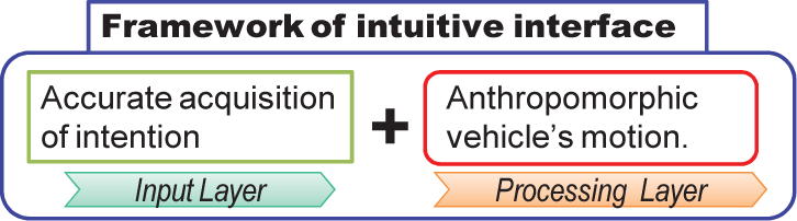
The framework of the intuitive interface.
If the interface extracts human intention, and if the vehicle moves like a human, then the human feels this operation to be intuitive.
Therefore this research proposes motion design which makes vehicle motion anthropomorphic by focusing on the processing layer of the interface. In this paper, we assume that the human intention can be extracted accurately and consider the vehicle's motion after the intention is obtained. The target vehicle is a non-holonomic vehicle. The reasons for this are: this type of vehicle is completely different from humans in terms of D.o.F for locomotion. Furthermore, its mechanism is simple and is adopted as a mobile mechanism for many mobile platforms. The target (designing) motion is a lateral motion which is difficult for non-holonomic vehicles.
This paper is organized as follows: we show the outline of the anthropomorphic motion design for the vehicle in Section 2; the non-holonomic vehicle which is the target vehicle of this paper is introduced in Section 3; in Section 4, the preliminarily experiment suggests which body parts should be measured for making normative motion and the results show that the representative body part is the hip. Then, velocity and angular velocity of the hip are measured. We propose the motion design by deriving normative motion for the vehicle and implementing its motion to the actual vehicle in Section 5; the designed motion is evaluated by a subjective experiment and we confirm that the proposed method can allow the vehicle's motion to imitate human motion in Section 6. We conclude this paper in Section 7.
2. Design strategy
In order to create an anthropomorphic motion, the motion model, which is a normative motion, is needed. There are briefly two methods to obtain such a model.
In the first model each joint motion is derived based on mathematical model by setting boundary conditions like the jerk minimum model [9] and the minimum torque change model [10]. The researchers in this field (e.g., [10–11]) discuss the reaching problem on the robotic manipulator. The coordinate system of the manipulator is fixed to the ground, namely the working area is restricted. Thus, this is not suited for vehicle motion design.
In the second model the human motion is measured and replayed on the machine [12–13]. Much of the research on this has considered the motion planning for a humanoid robot and there is no research implementing human motion on a mechanical system whose D.o.F. and configuration are different from that of a human. Of course the configuration and D.o.F. are different between humans and humanoid robots, but both are almost the same in comparison with a vehicle. Therefore, there is no research which proposes an anthropomorphic motion design with a vehicle which is completely different from that of humans.
Furthermore, in the case of adopting human motion as normative motion, the problem remains: whose motion should be adopted? Even if the subjects make the same movement, the motion of each subject is a little different due to the difference in individual physical characteristics and peculiarities. Therefore, the normative motion may not be specifiable.
Based on the above, this paper considers extracting one normative motion (we call it “standard human motion”) from several human motions by adapting them to control inputs of a vehicle, and implementing them to the actual vehicle (Fig. 3). The outline of the design strategy is:
Concept of standard human motion. We settle the control inputs of a vehicle. The representative body part which shows normative motion for the control inputs is selected by preliminary experiment. The motion of the selected body part is measured. The measured motion data is plotted on a phase plane. The motion of each subject is different, becaue the motion is described in time domain. Therefore, to eliminate the time component, the motion is described in the phase domain. Each motion on the phase plane is fitted to an ellipse by using the least square method. Each subject motion is almost the same ellipse. We adopt its average ellipse as the normative motion called “standard human motion”. The obtained standard motion is returned to the time domain and implemented to a vehicle.
We explain it in detail in the next section.
3. Non-holonomic vehicle
We adopt a differential wheeled vehicle (Fig. 4), which has a velocity constraint and typical non-holonomic vehicle, as a target vehicle system.

Non-holonomic vehicle.
In Fig. 4, W[m], R[m], θ[rad] and L[m] are vehicle width, radius of wheels, angle relative to x axis and distance travelled respectively. In addition, the angular velocity of the vehicle
Here we set the velocity vref and the angular velocity ωref as control inputs, and the relations to the rotation speed of right and left wheel ωr, ωl are as follows.
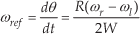

From the above, the rotation speeds of both wheels ωr, ωl which realize vehicle velocity vref and angular velocity ωref are as follows.

If we can describe these parameters based on the standard human motion, the motion of the vehicle can be approximated to human motion, because vehicle velocity vref and angular velocity ωref are control inputs.
4. Representative human body part
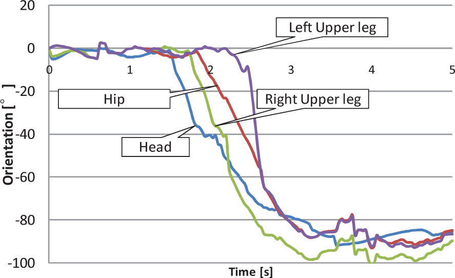
In order to describe vref and ωref as the standard human motion, we need to measure the human motion. However there is a problem: which body part should be measured? In order to find a representative body part for measurement, we did a preliminary experiment. In this experiment, we measure the orientations θ (Fig. 5) of the lower body (legs), hip and head, while subjects walk straight and turn at a right angle and then walk straight again. The motion of the non-holonomic vehicle is limited to a two dimensional plane, namely the height of the vehicle is constant. Thus, we focus on the orientations of the body parts without consideration of body height.
Definition of the coordinate.
4.1 Measurement method
The motion capture system using stereo vision is employed. The frame rate is 30 fps. Fig. 6(a) is the example of the experiment and Fig. 6(b) is the screenshot of the modelled human motion in motion capture software.

(a) Human motion (b) Human motion in motion capture software.
4.2 Results
Five subjects were recruited and one of the results is shown in Fig.7. This figure shows the orientations of the head, hip, right leg and left leg. From the results, although the time for motion is different with each subject, it can be observed that head orientation is phase lead and the orientation of the leg shows phase lag when the hip orientation is adopted as the reference. From the above, it can be supposed that the representative body part is the hip in the case of human locomotion. Therefore, we adopt hip as the representative part and measure its velocity v and angular velocity ω.
Motion of human body parts.
5. Deriving standard human motion
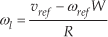
In order to derive the standard human motion, we have to specify the target motion and measure several human motions while the subjects are executing the target motion. We adopt the lateral motion (Fig.8), which is a typical restricted motion for a non-holonomic vehicle, as the target motion. With regard to this motion, we measurev and ω of the hip.

Experimental motion for deriving standard human motion.
5.1 Measurement of target motion
The motions of seven subjects were measured. We requested subjects to walk in the lateral(x) direction with changing orientation, namely we restricted the motion to that of a crab's walk. However, we did not limit the time for walking and we did not instruct them that the body orientation at the start and finish points must be exactly same. That is to say, we measured the subjects' natural motion. The results are shown in Figs. 9 and 10. These graphs show that the periods and amplitudes are different for each subject. These differences come from the individual physical characteristics and peculiarities, in addition, the motions in Figs. 9 and 10 are time series data. Therefore, it is difficult to specify one motion from these graphs as the standard human motion.

Trajectory of angular velocity of human ω.

Trajectory of velocity of human v.
5.2 Specify the standard human motion
In order to easily find out the standard human motion, each subject's motion should be non-time-series data. To do so, we consider plotting v and ω on the phase plane. By considering on the phase plane, we can ignore the time component in the motion data, and we can observe the relation between v and ω.
5.2.1 Extraction of fundamental component by DFT
However, the mapping data should be periodic to plot on the phase plane. v and ω depicted in Figs. 9 and 10 contain harmonic content, therefore, if these data are mapped to phase plane directly, it is supposed that the plotted line is a complicated shape. So it is not preferable to directly map the data without data processing.
Hence, the fundamental components are extracted by using the Discrete Fourier Transform (DFT) from measured v and ω, and then afterwards extracted data are plotted on the phase plane.
Fig. 11 shows one of the examples of v, ω, and extracted fundamental components using the DFT. Although the original data contained walking cycles, noise and so on, the extracted fundamental components do not have such noise and show the non-linearity of the motion, namely it expresses the fundamental motion or primitive motion.

Extraction fundamental component from human motion by DFT.
5.2.2 Mapping to the phase plane
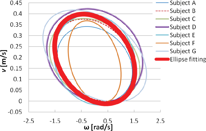
The fundamental components are extracted from seven subjects' motion data, and each fundamental component is plotted on the phase plane of which the horizontal axis is ω and the vertical axis is v. The plotted results are shown in Fig. 12. On the phase plane, the motions of each subject are almost the same, even if the motions are different in the timed domain, because the phase plane does not contain the time factor. Therefore, we can assess the data which is different in time domain by introducing the phase plane.

Human body motion on the phase plane.
5.2.3 Ellipse fitting
In order to ascertain the standard human motion which is the normative motion for the vehicle, we need to specify one motion (trajectory) from the phase plane (Fig. 12). Each motion of the subject draws almost the same ellipse trajectory in Fig. 12. Based on this, we create an ellipse fitting [15] by using the least-square method, and adopt the fitted ellipse as the standard human motion.
The ellipse fitting result is shown in Fig. 13. An approximated ellipse line is regarded as the average of each subject's motion, therefore this ellipse trajectory is adopted as the standard human motion which is the normative motion for the non-holonomic vehicle. This ellipse trajectory can express motions which have differences in time domain and can absorb differences caused by individual physical characteristics and peculiarities.
Ellipse fitted line: standard human motion.
5.3 Replaying the standard human motion
The standard human motion in Fig. 13 does not contain time and shows simply the phase relation between v and ω. In the case of operating the actual system, the consideration of time is needed, therefore the motion pattern must be expressed in the time domain. For this, the standard human motion is converted into the time domain by inverse mapping. Then the time series data of v and ω are derived, and these data is inputted into the control input as vref and ωref. In this inverse mapping, we need to set the period. The average motion time of seven subjects which is 3.3[s] is used for the period. The obtained time series data of vref, ωref are shown in Fig.14. These data were derived by parametric representation of the standard human motion with parameter t[s]. By using Fig. 14 as the control inputs and driving each wheel by (3) (4), then the motion of the non-holonomic vehicle can be approximated to the human motion.

Control inputs derived from standard human motion.
6. Evaluation experiment
In order to consider the human impression by replaying the standard human motion, an evaluation experiment using the Semantic Differential (SD) Method was conducted. In this experiment, 14 subjects were recruited. In order not to prejudice the subjects, we explained the purpose after the experiment.
Here, the actual vehicle being used in this experiment is shown in Fig. 15, and its specifications are summarized in Table 1. The angular velocity of right and left wheels ωr, ωl are controlled by PID control by using control inputs vref and ωref and (3), (4).
Specifications of non-holonomic vehicle.


Top view of the non-holonomic vehicle.
6.1 Conditions
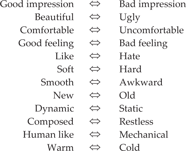
For this evaluation, we prepared the mechanical motion as control experiment. The mechanical motion is the motion shown in Fig. 16, namely the motion is the constant speed. We replayed standard human motion and mechanical motion was projected onto the screen, and the subjects answered the questionnaire while watching these motions. While answering the questionnaire, we repeated the motions according to each subject's requests. In the questionnaire, the following 12 pairs of antonym adjective words (Table 2) with seven grades, written in Japanese, were listed. The subjects marked the place where the feeling matched the word. Fig. 17 is the experimental scene while the standard human motion was replayed.
List of 12 pairs of antonym adjective words.

Control inputs of mechanical motion.

Vehicle motion controlled by standard human motion.
6.2 Results
Fig. 18 is the SD profile which shows the average score which was derived from the questionnaire. In this figure, the red line is the case of standard human motion and the blue line is the case of mechanical motion. The left side is a positive and the right side is a negative impression. From this figure, it was discovered that the subjects have a positive impression of the standard human motion compared with the mechanical motion. Next, the factor analysis was done based on the results of the SD profile. The factors were extracted by Varimax rotation, after deriving factor loading by using principal-factor solution based on the correlation coefficients between antonym adjective words. In this factor loading, the extraction criterion was that the eigenvalue was more than 1.0. Fig. 19 shows the factor loading. For the analysis, two factors were extracted.
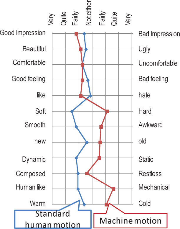
Obtained SD profile.

Factor loading.
Fig. 19 shows that first factor represents “Human like, Soft, Smooth”. The second factor represents the “Good feeling, Good impression, Beautiful”. Fig. 20 and 21 are factor scores which indicate the relation mentioned above and the questionnaire results of subjects. Fig. 20 is the case of mechanical motion and Fig. 21 is the case of standard human motion. In these figures, the horizontal axis is the first factor which mainly shows the impression of “Human like” and the vertical axis is the second factor which mainly shows the impression of “Good feeling”. Therefore, the right-half plane is the area of “Human like” impression. Conversely the left-half plane shows the mechanical motion feeling. In case of the mechanical motion (Fig. 20), the majority of impressions are plotted on the left-half. In case of standard human motion (Fig. 21), the majority of impressions are plotted on the right-half. From above, it is confirmed that the impression of standard human motion is anthropomorphic in comparison with conventional vehicle motion, leading to a positive human feeling.

Factor score in case of mechanical motion.

Factor score in case of standard human motion.
7. Conclusion
This paper we proposed an anthropomorphic motion design for a non-holonomic vehicle. In order to create anthropomorphic motion, a certain normative motion for a vehicle was needed by using measured human motion data. When specifying one normative motion, there was a problem: whose motion should be adopted? For this, this paper considered extracting one normative motion (we call it “standard human motion”) from several human motions by adapting the control inputs of a vehicle and implementing them to the actual vehicle.
The differences among subjects' motions come from the individual physical characteristics and the subjects' motions are time series data. In order to specify standard human motion, each subject's motion should be non-time-series data. To do so, the subjects' motions were plotted on the phase plane. By considering on the phase plane, we can ignore the time component in the motion data. On the phase plane, each subject's motion is almost the same ellipse, and then we fitted these ellipses to one ellipse by using the least square method. Thus, we adopted this fitted ellipse as “standard human motion”. The standard human motion was implemented on the actual non-holonomic vehicle and evaluated by using the Semantic Differential (SD) method. From the results, it was discovered that our motion design can create anthropomorphic vehicle motion.
For future research we plan to realize the intuitive interface and will consider combining this motion design method and an excellent input layer which can obtain the control input, and thus verify our intuitive interface framework (Fig. 2).