
Abstract
Robot force control is an important issue for intelligent mobile robotics. The end-point stiffness of a robot is a key and open problem in the research community. The control strategies are mostly dependent on both the specifications of the task and the environment of the robot. Due to the limited stiffness of the end-effector, we may adopt inherent torque to feedback the oscillations of the controlled force. This paper proposes an effective control strategy which contains a controller using quantitative feedback theory. The nested loop controllers take into account the physical limitation of the system's inner variables and harmful interference. The biggest advantage of the method is its simplicity in both the design process and the implementation of the control algorithm in engineering practice. Taking the one-link manipulator as an example, numerical experiments are carried out to verify the proposed control method. The results show the satisfactory performance.
Keywords
1. Introduction
With the wide demand for robots in industrial systems, the research and application of robotic designs and control have rapidly gained widespread popularity [1]-[4]. During robotic operations, the end-effectors will contact with the work environment and thus they produce the force each other. In order to use manipulators in some tasks such as machining, grinding, finishing, etc., we have to deal with the unwanted features of this interaction based on the direct contact between the robot and the product. At the end of the reaching phase and positioning to a workplace, the number of degrees of freedom of the robot arm decreases and the plant in the robot control system undergoes structural modification. In the early stage, force control was implemented by a Proportional Integral Derivative (PID) controller [1]. Later, the advanced adaptive control method [3] [5] and robust method [6] were accepted. Traditional algorithms include the sliding mode control [7], fuzzy control [8] and neural network methods [9]. Recently, the method of force control synthesis [10] has been applied to contact force control.
With the requirements for higher accuracy in industrial operations, better energy efficiency and lower manipulation costs have resulted in considering the inherent oscillating torque feedback and harmful interference. In these problems [11]-[18], the knowledge of kinematics between the joint and contact space is needed, and the contact surface should be considered. As a result, the majority of the proposed control schemes for robot contact tasks require exact knowledge of the kinematics in order to reach performance requirements. However, in many practical applications, kinematic uncertainties may arise in both free and constrained motion [19][20]. The designed control structure not only eliminates the negative influence of the torque feedback and anti-jamming performances, it also effectively resolves the robust design problem caused by the uncertainty of model parameters. Based on an engineering optimization algorithm, the advantage of this proposed method is to simplify the design process and easily implement engineering applications.
2. System Formulation
The end-point stiffness of a robot kinematic chain represents the crucial problem in force control [21]–[26]. The force generation in the robot end-point starts at that moment when the end-effector reaches the working position. The rest of the kinematic chain preceding the last link joint carries on with the subsequent positioning of the robot arm along the desired trajectory. To simplify the synthesis of the force control system, we concern the axis of the last link joint parallel to the gravitation force. It can eliminate the influence of the gravitation force in the joint. The main role of the last link joint's servo system is to keep the tool in adequate contact with the workpiece. Therefore, the torque proportional to the desired contact force should be generated. From this point of view, the equilibrium of the torques and forces at the driving motor shaft can be expressed by

where τD and τL stand for the driving and the load torque, respectively, J is the moment of inertia of the rotating mass and ω represents the angular velocity.
The dominant element of the load torque takes into account some specific features of the last link motion at the motor shaft corresponding with the reaction to the controlled force F.

where r is the last link length and i stands for the gear ratio of the gearbox. The efficiency of the gearbox is regarded to be k. For the period of the force generation, we suppose a small and reversible deflection of the link. Thus, the force F in the end-point is considered to be proportional to both the length r of the link and the angle increment φ in the joint.

where Ke is the effective rigidity of the last link.
From equations (1), (2) and (3), we are ready to make the load torque feedback analysis. According to Fig. 1, the transfer function of the force is given by
Block diagram of the contact force

There is no damping from expression (4) in the system. Fig. 2 demonstrates the negative influence of the load torque feedback in the Bode diagram of the transfer function (4). The magnitude of the peak value at the resonance frequency ωr =1/T implies the output force oscillation, and consequently, the production quality radically decreases in the robotized technology. The force control structure is designed to eliminate this oscillation.
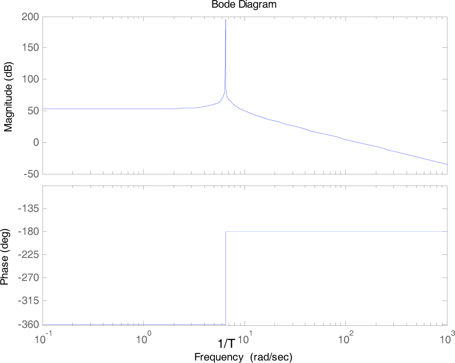
The Bode diagram of contact force
In practical engineering, when the force torque is controlled by a motor, we need to ensure that the robot has good torque output performance, so that we can achieve adequate control accuracy on the end-effector. It's a good way to control the robot joint by using a direct drive motor. The direct motor drive can simplify the mechanical design and eliminate the gear clearance, friction and other unfavourable factors by a rotor directly coupled with the driven joint. Meanwhile, it can guarantee high transmission accuracy and the motor output torque and joint torque are approximately equal. In this way, we can precisely control the motor torque. In this paper, a DC motor is used as the end-effector torque output.
In Fig. 3, U and I stand for the control voltage and the current of DC motor armature, respectively. Ta is an electromagnetic time constant of the motor. Ra is the total resistance of the armature circuit and C is the constant for both the voltage and the torque.
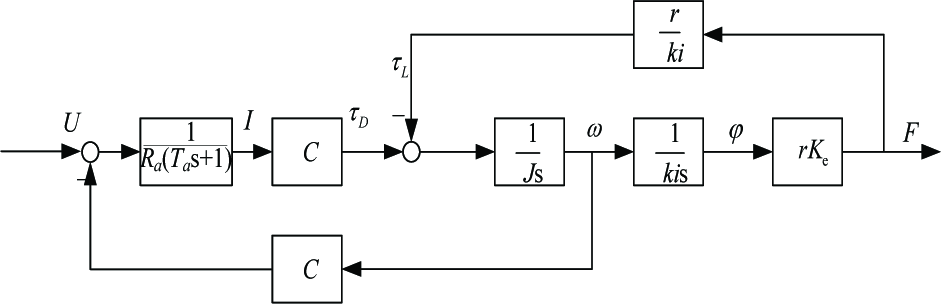
The controlled plant in a force control
3. Design of the Control Structure
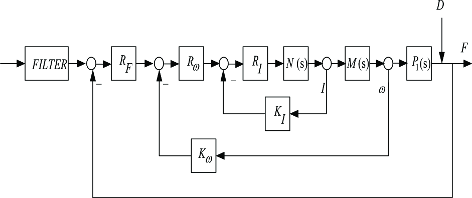
The motor of the direct drive robot has good output characteristics. It is directly coupled with the end-effector to ensure that the output torque and joint torque are approximately equal, and to facilitate the control and calculation of the torque. In order to compensate the drive error and further improve the performance of force control, the loop of the motor armature's current I is adopted and significantly improves the dynamics of the whole system. The velocity loop satisfies the requirement for the fast reaction to the oscillation. The force control loop should compensate the nested loop effectively.
From the block diagram of the contact force control structure in Fig. 4, the voltage signal UF1, Uω1 and UI1 stand for the desired voltage values. UF2, Uω2 and UI2 represent the measured voltage values. Meanwhile, RI, Rω and RF represent the current, voltage and force controller respectively. KI and Kω are the simple gain blocks of the current and velocity. D represents the output interference signal.

Block diagram of the force control structure
4. Controller design and simulation
Motivated by the feedback design in practice, this paper proposes applying Quantitative Feedback Theory (QFT) in the controller design. QFT is a frequency domain technique which uses the Nichols Chart (NC) in order to achieve a desired robust design about a specified region of the plant uncertainty. In most practical designs, iterations are inevitable, but QFT provides a trade-off method between controller complexity and specifications during such iterations.
The QFT design follows classical designs using Bode plots very closely. The transfer function model can be a fixed or uncertain set. If a problem requires that the specification meets with all transfer functions in the uncertain set, we call it a “robust performance” problem. That is, the performance specifications must be satisfied for all possible cases admitted by the specific uncertainty model. This is the major challenge to controller design satisfied the robustness of stability and performance.
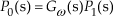
A standard QFT structure is shown in Fig. 5, where R(s) is the command input, F(s) the prefilter, G(s) the controller, P(s) contains the uncertain parameters of the controlled object and D1(s) and D2(s) are external input interference signals. The closed-loop transfer function of the system is given by
Block diagram of the QFT control structure

where L(s) is the open-loop transfer function of the system.

The disturbance closed-loop transfer function of input and output are

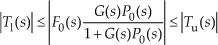
QFT extends to the frequency domain analysis in consideration of the classical control theory about the robust controller design of uncertain systems. We should take into account the uncertainty range of the plant, the system performance form templates and the border of the NC. After analysis and synthesis, the controller G(s) and the prefilter F(s) make the closed-loop uncertain system transfer function meet the stability requirements. In order to facilitate controller design, the force control structure is illustrated in Fig. 6.
The equivalent block diagram of force control structure
From Fig. 6, we need to design three controllers, i.e., RI, Rω and RF, and a filter. With the contact force generated, the control system must be able to quickly track and react to the oscillation. The system should ensure good robustness against the external disturbance and the model parameter uncertainty. According to the characteristics and requirements of the force control system, the outer loop controller R(s) and the filter are designed using QFT.
The design of controllers needs to follow the nested loop and the outer loop. The current closed-loop control can transform the control object to speed up the current track. The nested loop controllers contain RI and Rω. To improve the dynamics of the velocity control loop and take the physical limits of the systems state variables into account, the current controller RI is chosen in the form of a PI controller.

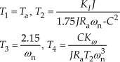
The control system, where time T1 = Ta, simplifies the design process and compensates the plant's dynamics. The value of the time constant T2 is reserved in the velocity controller design.
Through our investigation, the transfer function of the velocity control closed-loop is designed using the standard form of the ITAE optimum control theory. The method provides a satisfactory magnitude of the velocity overshoot and non-periodical under-damped response. Using this method, we choose a characteristic polynomial for the closed-loop function of the velocity control in the form of

where the standardized time ωnts = 8. The PI velocity controller is used to obtain good static and dynamic performance.

The time constants required in nested loop controllers are in the function forms of the parameter ωn
Based on the dynamic characteristics of the velocity loop in the frequency domain, the ωn value in the loop influences the velocity compensation of the undesired oscillation in the control system. In Fig. 7, the high ωn value can assure the compensation of the force oscillation by means of the velocity control. The transfer function of the uncertain plant P1(s) is given by
Set of magnitude diagrams of the force control loop

For the designed controller of the outer force loop, the nested transfer function and the uncertain plant P1(s) are in series to get the uncertainty model. The equivalent model of the outer loop is
Parameters for force control

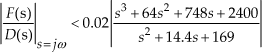
For robust stability, the results in a gain margin larger than 5.26 dB and a phase margin of about 50° are asked. Due to the under damped poles and zeros that exist in this plant, a number of specification design iterations are required for selecting the robust performance bounds. The lower and upper bounds are given as follows

The second design requirement is a tolerance on closed-loop stability, because the QFT design bounds derived from (6) are sufficient only to reduce the gain variation in the closed-loop responses by the required amount. This gives the following restriction on the peak magnitude of the closed-loop frequency response.

In addition, the robust performance specifications of plant output disturbance rejection are considered.
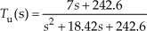
With the computed stability and performance bounds, the next step in QFT is to design a nominal loop function that meets its bounds. The loop is the product of the nominal plant and the controller. It has to satisfy the worst case of all bounds. The final interactively designed controller is given by

For each QFT control loop, it is necessary for the prefilter to further manipulate the closed-loop frequency response and to ensure that the system responses lie in the specific tracking envelope. Fig. 9 shows a characteristic frequency curve of the system closed-loop, where the dashed lines are the frequency domain tracking for the requirements of the border. This is achieved with a prefilter given by
Open-loop plot with the controller Closed-loop frequency response with the prefilter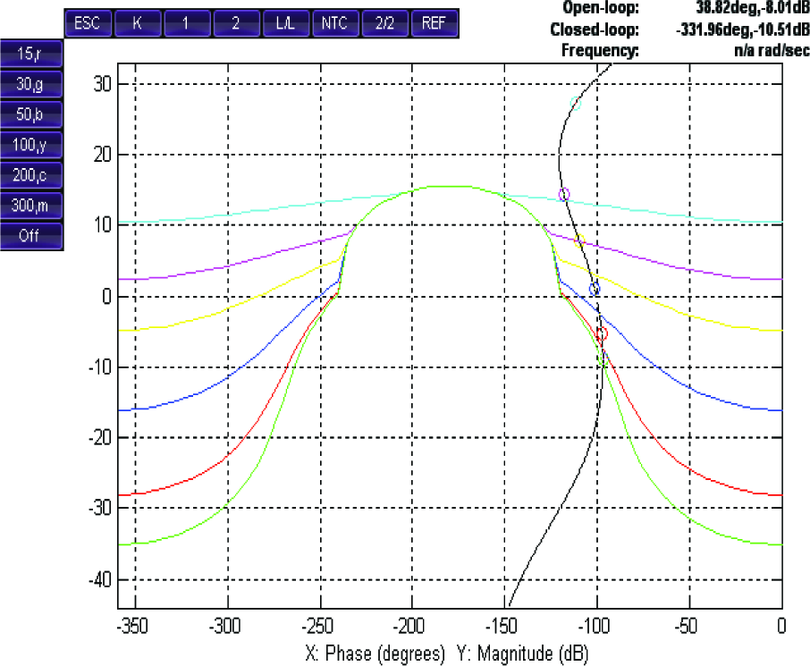

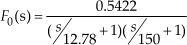
Fig. 10 represents the curve of anti-jamming in the conditions of the designed controller. Fig. 11 shows the step response of contact force control. The dashed lines represent the tracking requirements. From Fig. 10 and Fig. 11, we know the designed system meets with the performance goals well and has good robustness.

Analysis of robust output disturbance

The step response of the system
5. Conclusion
This paper concerns the issue of robotic force control in the case of parameter uncertainties in engineering applications. In particular, the effective rigidity of the last link is not exactly known and a certain range of parameter values are given. A novel method is proposed for contact force control. Firstly the inner current and velocity loop controllers are designed as PI controllers based on the ITAE optimum theory. Then, by using the robust design method of QFT, a force controller is designed for the outer force loop to achieve the desired tracking perf ormance as well as disturbance rejection. A numerical simulation example is used to demonstrate the derivation of the controller and its effectiveness. One distinct advantage of the method is that it can eliminate the negative influence of the torque feedback. Another advantage is that the robust design problem caused by uncertainty of model parameters and output disturbance is resolved. The method possesses the simplicity of both the design process and engineering implementation. Furthermore, QFT and the generalized predictive control can be used together in the contact force control structure when a contact transition occurs. A challenging extension of this work in the future is that the result of the paper can be used for a mobile NAO robot platform in order to test the viability of the proposed method in real experiments.