
Abstract
The design, dynamic modelling, and workspace are presented in this paper concerning cooperative cable parallel manipulators for multiple mobile cranes (CPMMCs). The CPMMCs can handle complex tasks that are more difficult or even impossible for a single mobile crane. Kinematics and dynamics of the CPMMCs are studied on the basis of geometric methodology and d'Alembert's principle, and a mathematical model of the CPMMCs is developed and presented with dynamic simulation. The constant orientation workspace analysis of the CPMMCs is carried out additionally. As an example, a cooperative cable parallel manipulator for triple mobile cranes with 6 Degrees of Freedom is investigated on the basis of the above design objectives.
1. Introduction
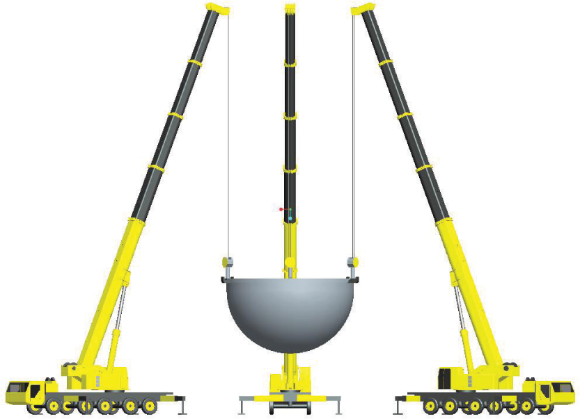
Mobile cranes are widely used for loading, mounting, carrying large heavy-duty loads and for work performed in the presence of obstacles of various kinds such as civil engineering for the construction of buildings, power lines and similar technological installations[1]. With the development of the manufacturing technology and demand of the modern engineering, cooperative operation of multiple mobile cranes has become more common in modern construction projects and manipulation of heavy-duty objects in recent years[2], such as the one shown in Fig.1.

Multiple mobile cranes
Multiple mobile cranes can be treated as cooperative multiple manipulators[3]. Multiple manipulators have become a mature research field, in which the problem of the implementation of cooperative manipulation on conventional set-ups has attracted an increasing interest of the research community[4]. Multiple robot manipulators have been studied as having many possible applications [5,6]. This is due to the extended capabilities that the multiple robot manipulators have to offer compared to the use of a single manipulator for the same task [7]. In the literature there is a variety of studies about multiple robot manipulators. Sun and Mills [8] have presented an approach to nonmodel-based decentralized controls of multiple robot systems utilizing structural flexibility in gripper design to avoid large unwanted internal forces acting on multiple robot systems. Kambhampati and Rajasekharan [9] have investigated a Lyapunov-based fuzzy logic controller for multiple robot system from a human motor-control perspective. Kumar and Garg [10] have considered a problem of sensor-based estimation and control of forces and moments in multiple cooperative robots. Fong et al. [11] have investigated multiple robot remote driving with collaborative control. Kim and Minor[12] have presented a kinematic motion control strategy for an n-axle compliant framed modular wheeled mobile robot, and simulation and experimental results validate and characterize the performance of the algorithms. Liu et al. [13] have investigated a motion-planning approach for coordinating multiple mobile robots in moving along specified paths. Linda and Manic[14] have presented fuzzy force-feedback augmentation for manual control of multiple robot system. Senthilkumar and Bharadwaj [15] have investigated multiple robot exploration and terrain coverage in an unknown environment, and the method can handle partially occupied cells and narrow door openings in the terrain and performs a complete coverage of the surface regardless of the shape of the environment by constructing multiple spanning trees simultaneously.
Similar to cable parallel manipulators (CPMs), the cooperative multiple mobile cranes can be viewed as the CPMs. The CPMs have potential advantages in terms of simple and light-weight structure, large reachable workspace, high acceleration capability, and easy reconfigurability [16–18]. For the preceding characteristics, the CPMs play an important role in many engineering fields, such as manipulation of heavy payloads for manufacturing and cargo handling, coordinate measurement, aircraft testing, super antenna, haptic devices, rehabilitation and welfare engineering [19–22]. For the past several decades, the CPMs have been extensively studied. For instance, due to cable slippage on the drum, Baser and Konukseven developed an analytical method for predicting the transmission error [23].
Different aspects like time optimal trajectory tracking [24], workspace [25, 26] and bounded cable tensions [27] were also investigated extensively. Leila and Amin [28] investigated the dynamics of wire-actuated parallel manipulators with a constraining linkage by Lagrangian method. Flatness-based trajectory tracking control for a kinematically undetermined three-cable suspension manipulator has been investigated by Heyden and Woernle [29]. Oh and Agrawal [30] have considered a problem of positive tension controllers for cable suspended robots with redundant cables.
Recently, cooperative cable parallel manipulators for multiple mobile cranes (CPMMCs) are finding increased use in a wide variety of modern engineering applications. In addition, the CPMMCs can handle complex tasks that are more difficult or even impossible to perform for a single crane. In this investigation, the design, dynamic modelling, and workspace of the CPMMCs are presented. The remainder of this paper is organized as follows: Section 2 describes the design model of the CPMMCs. Then, kinematics and dynamics of the CPMMCs are performed in Section 3. Workspace analysis of the CPMMCs is provided in Section 4. In Section 5, illustrative simulation studies highlight its performances. Finally, some concluding remarks are summarized in Section 6.
2. System description
In this paper, cooperative cable parallel manipulators for triple mobile cranes are taken as an example, and the three-dimensional model of the CPMMCs is established for the purpose of numerical analysis(see Fig. 2). The CPMMCs consist of three mobile cranes and suspend the payload by three cables within the workspace by coordinating the action of each mobile crane. Each single mobile crane is mainly composed of a telescopic subsystem, a slewing subsystem, a luffing subsystem and hoisting subsystem. For each cable, one end is connected to the hoisting point of payload, while the other one rolls through a pulley fixed on the top of telescopic boom and is then fed into the drum of hoisting subsystem.
Three-dimensional model of the CPMMCs
A simple schematic sketch of the CPMMCs structure model is shown in Fig.3, which provides both a three dimentional view and a top view of CPMMCs with the associated coordinate systems. The three mobile cranes are arrayed at the vertex of the triangle O1O2O3 on the ground.

(a) Schematic sketch of the CPMMCs; (b) A top view of the CPMMCs
At the center of the triangle O1O2O3, a global coordinate system O (XYZ) is established. The distance between the endpoint of boom Ai and the corresponding hoisting point of payload Bi is Li (i=1,2,3). At the center of the gravity of the payload, a local coordinate system O' (x'y‘z’) is established. The mechanical configuration of a QY100k mobile crane is illustrated in Fig.4.

Schematic sketch of a mobile crane
For simplicity, we make the following assumptions.
Three mobile cranes of the same type QY100k are chosen in the CPMMCs, made in Xuzhou Heavy Machinery Co., Ltd of XCMG.
In order to suspend the payload smoothly and flexibly, the mobile cranes are expected to be able to luff, slew and hoist simultaneously as manipulators, which can be realized by cooperative control system of mobile cranes. However, the mobile cranes are expected to move with a certain regulation to avoid collision with each other during the cooperation and to simplify calculation. Therefore, the hypothesis is put forward that the triangle A'1A2'A3' whose vertexes are the projection points of the endpoints Ai is a equilateral triangle (see Fig. 3).
The body of mobile crane is regarded as rigid.
The payload is homogeneous object.
The cable is treated as a massless body and the flexibility is neglected.
Inertia force due to the body of the mobile crane is neglected because of the slow luffing and slewing speed.
The maximum acceleration in the vertical direction is smaller than the acceleration due to gravity.
3. Kinematics and dynamics
According to the geometric relationship of the CPMMCs in Fig.3, the coordinates of three mobile cranes can be derived as
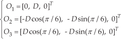
where D is the distance between each mobile crane and the reference point O.
The coordinates P ∋ R6 describe the spatial position and orientation of the payload. xp, yp, zp represent three Cartesian coordinates and α, o, n represent three Bryant angles.

Hence, the coordinates of hoisting point of payload Bi(xBi, yBi, zBi) can be obtained by

where R is the rotation matrix going from the local frame O' to the global frame O (as depicted in Fig.3). Additionally b′i is the coordinates of hoisting points relative to O'.
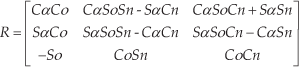

where s represents the distance between the hoisting point Bi and the reference point O'. Additionally, we denote cos by C, with similar substitution S for sin.
According to Fig.3, we can obtain the coordinates of Ai (xAi,yAi,zAi) as follows
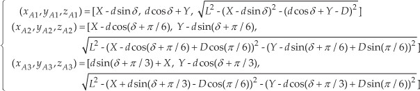
where (X, Y, δ) represents the coordinates of the center and the rotation angle of equilateral triangle A′1A′2A′3. L represents the boom length of mobile crane. d represents the distance between the center of equilateral triangle A′1A′2A′3and the vertex A.
The relationship between the cable length li and the endpoint of boom Ai as well as the corresponding hoisting point of payload Bi, can be easily obtained as follows

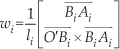
Hence the cables exert zero-pitch load wrenches on the payload which take the following form[31]
The gravity wrench takes the form

where g is the acceleration due to gravity.
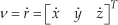
According to Eq.(2), the translational velocity v of the payload relative to O is the time derivative of its Cartesian coordinates r.
The angular velocity ω can be generated as

where


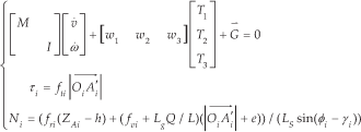
On the basis of geometric methodology and d'Alembert's principle, the dynamic equations of the payload can be formulated as

where M is the mass matrix of the payload relative to its center of gravity, while I is inertia matrix of the payload relative to its center of gravity relative to O'. Ti(i = 1,2,3) is the tension of the ith cable, that is the force acting on the hoisting subsystem.
Decomposing the cable tension Ti in the vertical direction, radial direction and tangential direction, three component forces can be formulated as

where fvi is the vertical component force, fri is the radial component force and fti is the tangential component force, respectively.
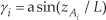
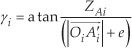
According to Eq.(15) and Fig.4, the force Ni acting on the luffing subsystem and the torque τi acting on the slewing subsystem can be easily obtained by


where γ is the luffing angle of mobile crane and φ is the angle between the cylinder and ground. Here h represents the vertical distance between the lower hinge joints of the boom and cylinder. e is the horizontal distance between the lower hinge joint of boom and the slewing axle of mobile crane. Lg is the distance between the lower hinge joints of boom and the center of gravity of boom. LS represents the distance between the lower hinge joint of boom and the upper hinge joint of cylinder.

Where f is the horizontal distance between the lower hinge joints of boom and cylinder.
The dynamic equations of the payload and the force acting on the subsystems of the CPMMCs are described by the following formulation
4. Workspace determination
The workspace of the CPMMCs by as the set of points where the payload can be positioned while all cables are in tension (Ti >0). Because of the mechanical structure limitation, the payload can not be suspended in a circle around the reference point. In other words, there is no dexterous workspace for CPMMCs. Therefore in this work, the constant orientation workspace of CPMMCs is generated, which is the set of points where the payload can be positioned while its Bryant angles θ = [α, o, n] T is fixed.
The constant orientation workspace of CPMMCs depends on the tension condition (Ti >0) and the following constraints:
The main searching space. Taking the engineering practice into consideration, the triangular prism is chosen as the main searching space, which undersurface is the triangle O1O2O3 and height is the length of the boom L. The main searching space can be expressed as follows
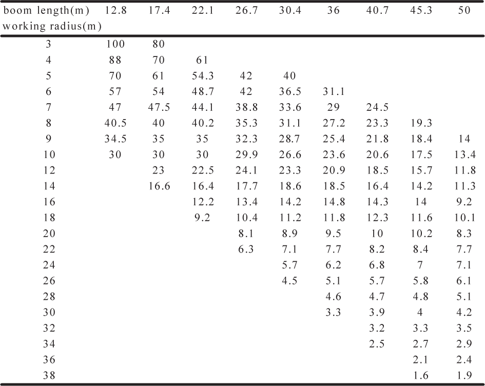
The working radius R. According to the Lifting capability of QY100k mobile crane (see Table.1), the working radius R of each mobile crane is limited after the fix of boom length and payload.
The working area. For a mobile crane, there are three working areas in terms of the slewing angle: left area, right area and back area. Generally speaking, the stability when the crane works in the back area is better than works in two side area. Hence the constraints of slewing angle of each mobile crane can be expressed as follows
The cable tension. According to Table.1, the cable tension should be smaller than the lifting capability when the working radius and boom length are fixed i.e., it must hold


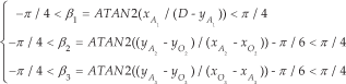

A general numerical workspace generation approach is employed here. The main searching scope is fixed at first. Thus, a series of points in Cartesian coordinate system are determined. According to the Eq. (24), a series of the working radius Ri can be calculated. From Eq. (25), the slewing angle β1 of each crane can be calculated. Then, the cable tension Ti can be obtained from Eq. (14). At the end, the points are checked and those satisfying all the constraints will generate the constant orientation workspace of CPMMCs. The flowchart of generating the constant orientation workspace of the CPMMCs is shown in Fig. 5.

Flowchart of generating the workspace of the CPMMCs
5. Results and discussions
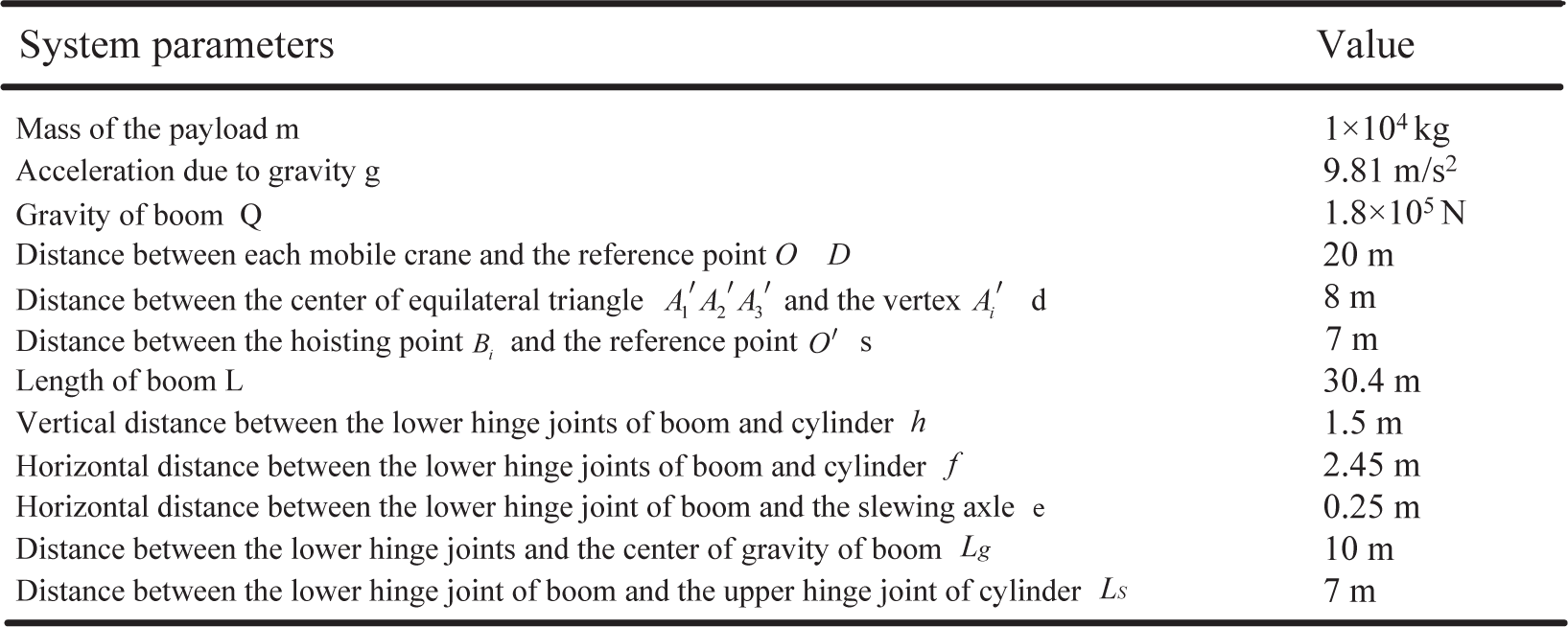
A simulation study was carried out with MATLAB for three mobile cranes of the CPMMCs have the same structure parameters. The parameters of the CPMMCs are listed in Table 2.
According to the flowchart of generating the workspace of the CPMMCs as depicted in Fig. 5, the constant orientation workspace can be shown in Figs. 6 and 7. The whole workspace is approximately an axially symmetric column. The cable tensions become larger and working radiuses of mobile cranes become shorter with the increase of vertical coordinate of the payload. Consequently, the lifting capability of each single mobile crane decreases, according to the indications of Table 1, which causes that the upper part of the column displays a conoidal configuration as shown in Fig. 6.
Lifting capability of QY100k mobile crane
Main parameters of the CPMMCs

Workspace of the CPMMCs.

Top view of Workspace of the CPMMCs.
On a second simulation, the payload of the CPMMCs is presented to move along a given spatial trajectory. The spatial trajectory can be expressed as

The payload of the CPMMCs moves along the trajectory as shown in Fig. 8.

Trajectory of the payload
It can be seen from Fig.9 that the cable lengths li of mobile cranes showed downtrend with operation time when following the trajectory of the payload, which is reasonable since the payload rises during the simulation. Figs.10 and 11 display the curves of slewing and luffing angles for the mobile cranes, respectively. From Figs.9–11, it should be noted that the cable lengths as well as the slewing and luffing angles smoothly and periodically, obviously because of the payload moving along a spiral trajectory.

Cable length of the CPMMCs

Slewing angle of mobile cranes

Luffing angle of mobile cranes
Fig.12 shows the time histories of cable tensions exerted on the payload. One can observe that the tension of each cable varies smoothly nearby 3.5×10⁴ N, which is slightly larger than one third of the weight of the payload. Compared with a single mobile crane, the CPMMCs have much better lift capability. In addition, the fluctuation of cable tension increases during the motion.
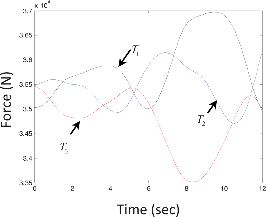
cable tension
Figs.13–15 show the curves of the vertical force component fvi, the radial force component fri and the tangential force component fti, respectively. Referring to Figs.13–15, it can be seen that the vertical force component fvi is the maximum component of cable tension. In addition, the vertical force component has a larger fluctuation than any other force component with operation time, which is probably the primary factor for the fluctuation of cable tensions Ti as illustrated in Fig.12.

Vertical component of cable tension

Radial component of cable tension

Tangential component of cable tension
Fig.16 illustrates the cylinder force of the mobile cranes. From the simulations, one can see that the cylinder force has a close relationship with the xp and yp coordinates of the payload, which are periodic functions of time as expressed in Eq. (27).

Cylinder pressure of mobile cranes
Fig.17 displays the curves of the torque acting on slewing subsystem of the CPMMCs. As it is seen, the curves of the torque are basically in accordance with the curves of the tangential force component fti of the cable tension.
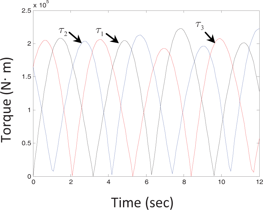
Torque acting on slewing subsystem
6. Conclusions
This paper presents the design and analysis of cooperative cable parallel manipulators for multiple mobile cranes (CPMMCs) with 6 Degrees of Freedom. In this investigation, a detailed design and implementation of a virtual prototype model of the CPMMCs is performed. Dynamic modelling of the CPMMCs is addressed and presented together with dynamic simulation. The inverse kinematic and dynamic problems of the CPMMCs system are resolved on condition that an operation path of the end-effector is given. Then, workspace analysis of the CPMMCs is provided based on the structure constraints of the CPMMCs. Finally, illustrative simulation studies highlight its performances, which lay a foundation for the further research on optimization and real-time control. In addition, the methodology presented in this work could be used as a guide for the design of cooperative multiple manipulators.
Footnotes
7. Acknowledgments
This work was supported by the National Natural Science Foundation of China (50905179, 51275515), the Visiting Scholar Foundation of Key Lab in University (GZKF-201112), the Six Talent Peak Foundation of Jiangsu Province, and the Priority Academic Program Development of Jiangsu Higher Education Institutions. The authors also appreciate the comments and valuable suggestions of anonymous referees and editors to improve the quality of the paper.