
Abstract
In this paper, a novel control methodology for automatically manipulating micro/nano particles by using a Scanning Probe Microscope (SPM) is presented. First of all, a mathematical model of micro/nanomanipulation, including the interactive forces and dynamics between the tip, particle and substrate along with the roughness effect of the substrate, is described. Then, the L1 adaptive control design for the manipulation system of micro/nano objects is presented, which consists of a state predictor with fast adaptation, a piece-wise continuous adaptive law and a low-pass filtered control design. This control framework can handle nonlinear uncertainties and ensures uniformly bounded tracking performance. The tracking performance bound can be systematically improved by reducing the step size of integration. Rigorous mathematical proof is provided. Simulation results demonstrate the effectiveness of the presented L1 adaptive control law on the micro/nanomanipulation model.
1. Introduction
Micro and nano-robotics investigate the handling, manipulation and assembly strategies of objects on both micro and nanoscales. Top-down approaches based on contact manipulation and tweezers have been studied in [1–2] with applications in chemical, material, electronics, pharmaceutical and medical areas. On the other hand, since the invention of the Scanning Probe Microscope (SPM), it has been widely used to provide topographic images with true atomic resolution. Meanwhile, in the recent decades, another advantage of SPM is attributed to the manipulation of micro/nanometre size objects and structures by implementing its probe as a manipulation tool [3]. As a first and critical step for achieving any complex functional micro/nano devices or structures, micro/nanomanipulation techniques can be used for DNA and protein study, data storage and nanotube or surface film characterization, where sub-micron or nanometre scale resolution is imperative.
Traditionally, SPM systems involve 2-D manipulation tasks such as lithography [4], dissection [5] and assembly [6]. By turning off the servo feedback and applying open-loop control routines, the SPM tip can be lowered towards the substrate and touch the objects, which can be subsequently pushed or pulled mechanically. For the time being, most of the operations have to be done manually [7], which consumes a lot of manpower and time. Therefore, in order to facilitate the transition of nanotechnology products into practical industry, the challenges in fully automatic manipulation and handling of micro/nano objects need to be addressed and overcome.
To this end, an automatic control law to govern the SPM piezoelectric actuators has to be developed. One of the obstacles is that physical and chemical phenomena at the micro/nano scale have not been well understood. Moreover, the forces acting on that scale usually cannot be measured directly. Although extensive studies have been conducted to analyse the adhesive forces between SPM tip, manipulated object and substrate [8–10] in mechanical pushing procedures, an accurate mathematical model with exact expression of the forcesto assist control design for manipulation is still unavailable. Furthermore, some comprehensive beam models have been introduced in the literature [11] by considering the shear deformation and rotary inertia representing the system response in a more highly structured fashion, but they are too difficult for real-time control implementation particularly when augmented with the ever-present nonlinear interaction force [12].
In the meantime, real-time visual information is not available for feedback while the SPM probe is programmed as a manipulation (pushing) tool through the manipulation routine. Hence, a high-level automation scheme is difficult to implement even with the help of augmented virtual reality techniques [7], because only an empirical model is utilized to observe the actual nano environment.
Additionally, SPM tips and usually some of the experimental samples to be manipulated are fragile, which may be easily damaged with improper applied force. Therefore, how to design an appropriate control algorithm for the handling of micro/nano scale objects under the circumstance of high nonlinearities and uncertainties still poses a great challenge.
The control of nonlinear uncertain dynamic systems with unknown disturbance has also attracted extensive interest from the control community [13]. Adaptive control methodologies in particular have been widely adopted to provide systematic solutions for systems whose behaviours can change under different operating conditions [14]. Specifically, in order to cope with the unknown system dynamics within micro/nanomanipulation, an adaptive controller has been recently developed in [15], while neural networks (NN) have also been employed in the controller designs [9]. However, the transient performance of the system cannot be guaranteed due to the learning phase of NN. On the other hand, by constructing a parallel reference system, a novel architecture for the control of nonlinear systems has been developed in [16], named an L1 adaptive controller. In the presence of unknown high-frequency gain, time-varying unknown parameters and time-varying bounded disturbances, fast adaptation and satisfactory steady responses are delivered.
Therefore, in this paper, an L1 adaptive feedback controller is discussed to perform autonomous manipulation tasks of micro/nano objects by using an SPM system. It can be proven that the L1 adaptive controller can ensure a uniformly bounded tracking performance for the SPM piezoelectric drive. The bounds of all the error signals within input and output signals in the sense of L∞ norm between the actual system and the desired system can be systematically decreased by reducing the time step of integration. Thus, the applied force on the tip and manipulated object can be rendered appropriately. Meanwhile, the nonlinearities within piezo actuators usually arising from high variation in control signal could be mitigated. Finally, the feasibility of the proposed scheme is validated in a simulation environment.
This paper is organized as follows. First, in Section II, the modelling of the micro/nanomanipulation process is presented. Then, the L1 adaptive control law is developed in Section III. The stability of the overall formation is presented in Section IV and Section V presents numerical simulations. Section VI provides some concluding remarks.
2. Dynamic Model of Manipulation
In this work, only the scenario will be considered that the SPM tip makes contact with a particle and pushes it along the substrate without touching the surface. The drawbacks of manipulation with the tip contacting the surface are discussed in [10] and therefore this is not discussed further in this paper. Also, as a well-recognized problem, thermal drift has been extensively researched in the literature [17–18] and thus is assumed to be compensated for along the manipulation process.
Furthermore, various motion modes, including sliding, rolling and spinning, have been investigated in [10], and only the sliding mode is reported to most likely happen in a pushing manipulation task. Next, interactive forces are presented and a dynamic model to assist controller design is introduced.
2.1 Interaction Forces
Firstly, the interaction forces between the SPM tip, particle and substrate after the tip contacts the particle are shown in Figure 1 [10].

The interacting forces between the SPM tip, particle and substrate.
In this work, the SPM tip apex is assumed to be a spherical ball with radius Rt and the particle radius is denoted as Rp. θ is the pushing angle, which is defined as the angle between the pushing direction and the horizontal plane. Aps is the adhesion force between the particle and substrate. Fps and Ftp denote the particle-substrate and the tip-particle attractive/repulsive interaction force, while fps and ftp correspond to the frictional forces for the particle-substrate and tip-particle, respectively. Elastic deformation of the particle is possible and here only the elastic deformation between the particle and the substrate is considered. The indentation is denoted as dp.
Moreover, gravitational forces are relatively very small at the nano scale and, thus, are neglected [8]. The main components of the adhesion forces are van der Waals, capillary and electrostatic forces [8–9]. Therefore, the adhesion force between particle and substrate can be given by Aps = Apsvdw + Apscap + Apses.
van der Waals force:
Capillary force:
Electrostatic force: neglected for conducting particle. where H is the Hamaker constant, h is the particle-substrate distance and b is the peak to peak height of the surface irregularity. γ is the liquid (water) surface energy, e is the thickness of the water layer and r is the adius of curvature of the meniscus formed within the water layer. More details of the analysis of these contact and friction forces can be found in [2, 9], and the reference therein. It has to be noted that, in our controller design to be discussed in the next section, the exact values of those forces are not required to be known.
2.2 Dynamic Model
A satisfactory dynamic model of the pushing mechanism on a planar substrate is formulated in [8] and [9] considering all of the forces mentioned above. Usually, the microscope stage instead of the tip is driven by piezoelectric actuators to achieve a proper pushing force for the micro/nano particle. Therefore, a simplified differential equation governing the system can be given as [8]

where (xs, ys, zs) is the position of the stage on x, y, and z axis, respectively. (wx, wy, wz) is the resonant frequency and (Qx, Qy, Qz) is the amplification factor for the stage, which can be measured or obtained from producer. (ux, uy, uz) is the stage driving force generated by the internal piezoelectric actuators which can be seen as the control input signal. Now fps is the friction force and Fps is the attractive/repulsive interaction force between the particle and substrate, which are apparently nonlinear and uncertain functions of the pushing environment. For more details, please refer to [8] and [9].
For simplification purposes, equation (1) representing the manipulation system can be viewed as a second order nonlinear dynamic system and rewritten as follows

where x ≡ [xs ys zs] T is the system state and u ≡ [ux uy uz] T is the control input. Since the interaction forces between particle, substrate and tip cannot be exactly known, the function f(·) : ℝ6 → ℝ3 is considered to be an uncertain nonlinear smooth function matrix. d(t) ∈ ℝ3 represents the unknown external disturbance and the constant diagonal matrix W ∈ ℝ3×3 is defined as

whose eigenvalues are always positive. Thereafter, the objective of the controller design is to drive the stage to follow a desired trajectory xd = [xsd ysd zsd] T and guarantee a desired applied force on the cantilever at the same time. Since the lateral force has a direct effect on the deflection of the probe along the zaxis ζz, which is observed to be a function of the pushing angle θ [9], the control goal can be translated to keeping a desired trajectory zd during the pushing procedure by assuming that the topographic information of the substrate surface has been obtained beforehand.
Next, the following assumptions are proposed before going forward.
3. L1 Adaptive Controller Design
In this section, how to design the L1 adaptive controller for the micro/nano manipulation via the tip of the SPM is introduced. Firstly, the original system (2) can be rephrased in lower triangular form as

with x1 = x, x2 = ẋ and initial condition x1(0) = x0.
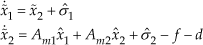
Thereafter, the following state predictor is developed as
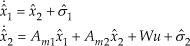
with x̂1(0) = x(0), x̂2(0) = ẋ(0). Am1, Am2 ∈ ℝ3×3 are user defined, such that
Thereafter, the adaptation laws are designed to be

where
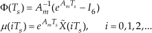
I6 ∈ ℝ6×6is the identity matrix and Ts > 0 is the adaptation sampling time, which is determined by the clock speed of the DSP chip within the microscope controller.
Then, the control law is proposed as follows

where

C1(s) needs to ensure that C1(s)Hm(s)−1 Hum (s) is strictly-proper.

In order to assist the proof of the stability of the closed-loop system, the following preliminary terms are defined. Let
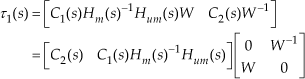
and the norm of τ2(s) is given by

Further, let

and
where γ
x
is introduced later. Define

and

where λmax(·) denotes the maximum eigenvalue.
Moreover, the choices of C(s) and sampling time Ts need to ensure γ
x
exists such that

Next, the performance bounds of the L1 adaptive control system are theoretically proven.
First, the error dynamics is obtained by subtracting (4) from (5) as
Hence, the theoretical results on the performance bounds of the closed-loop system (4) with the L1 controller can be presented.


and

where γx˜ and γx is introduced in (17) and (18) respectively, and


which implies that

where ‖Xt′‖L∞ denotes the truncated L∞ norm of X at the time instant t′.
It immediately follows (19) that
where

for the simplification purpose. Equation (26) further implies

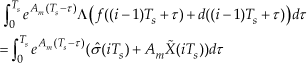
Substituting (6) into (28) yields

Since the system satisfies the Lipschitz condition, i.e., ‖f(X)‖ ≤L(γx)γx + B, and ‖d(t)‖ ≤ dm for t ∈ [0, t′], utilizing (13) and (14) results in

for (i + 1)Ts ∈ [0, t′].
According to the choice of adaptive law (6), one has

which further shows

Meanwhile, (29) provides

Hence, (32) and (33) together imply
Following (30) and (34), one obtains the following upper bound by consulting standard linear algebra

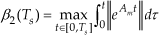
Subsequently, for all iTs + t ≤ t′, where 0 ≤ t ≤ Ts, by referring to (26) and (30), and the definition of β1(T), β2(T) in (15) and (16), one reaches the following upper bound as

which directly gives that

for all t ∈ [0, t′] from (17).
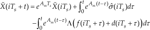
Furthermore, since X˜ = X̂ − X, and naturally
it follows from (5) that

Thus, one has the following upper bound as

over t ∈ [0, t′], where x0(s) = (sI – Am)−1 x0.
Meanwhile, recalling (8) results in the upper bound of control signal

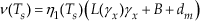
where τ1 is defined in (11). Substituting (41) into (40) yields
where τ2 is defined in (12), and

Therefore, by resorting to (35), one has

Eventually, by combining (37), (38) and (43), one gets the upper bound of X(t) as

Considering the stability condition, (44) becomes

which contradicts (25). Thus, it shows (21) is true and (20) is a direct outcome of (21) and (37). Furthermore, by consulting (21), (35) and (41), one has

which proves (22) and concludes the proof of Theorem 1.
4. Simulation Results
In this section, the proposed controller is applied toa manipulation task via the SPM system in a simulation environment. The control objective is to guide the stage movement to follow a desired trajectory such that an appropriate push force can be applied on the cantilever and also the particle.
The dynamics of the stage is modelled as (1) with wx,y,z = 2π fx,y,z, fx,y = 250Hz, fz = 18.7Hz and Qx,y,z = 20 in the simulation [20]. The manipulation task is assumed to be pushing a nano scale particle along a direct line over a mica surface with a constant prescribed speed v = 1000nm/s. The angle between y axis and the pushing direction is set to be 30°, i.e., xsd(t) = 1000 sin(30°)t and ysd(t) = 1000 cos(30°)t.
Meanwhile, Rp = 30nm in the simulation. To imitate reality and test the robustness of the control method under the roughness effects, the substrate surface is set as a sinusoid function with the amplitude of 0.1 nm. A bounded uniformly distributed external environmental noise d is imposed with a bound of dm = 1 nN.
The controller parameters used in this simulation are tabulated as below.
It has to be noted that the low-pass filters C1(s) and C2(s) are rendered the same to simplify the controller structure.
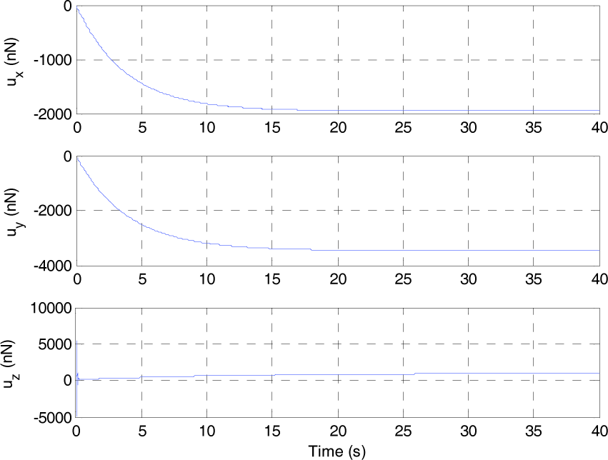
A typical system response using the proposed controller is shown in Figure 2 including the stage trajectory on x, y and z directions. Simulation results demonstrate that the L1 adaptive controller can drive the SPM stage to follow a preset curve with the presence of unknown system dynamics and external disturbance. The control input trajectories are also depicted in Figure 3, which verifies the boundedness of the control signals (ux, uy, uz).
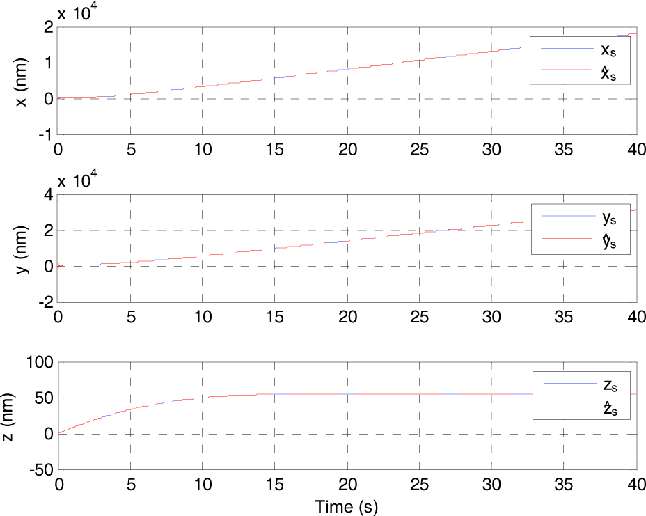
Simulation results of the proposed controller on the micro/nanomanipulation system: trajectories of the actual movement of the stage (solid lines) and the output of the state predictor (dashed lines).

Simulation results of the proposed controller on the micro/nanomanipulation system: control input.
Moreover, the deflection of the probe along the z axis ζz is also plotted in Figure 4. It shows that during the initial phase when the probe makes contact with the nano object, there is a sharp spike on the deflection. But as the stage is driven by the actuators, the nano particle is moved by the probe and the deflection converges to a constant value – approximately 0.2 nm.

Simulation results of the proposed controller on the micro/nanomanipulation system: trajectory of ζz.
In order to evaluate the sensitivity of the controller to parameter variations and test its robustness, a different set of parameters is adopted in the simulation as in Table 2.
Summary of parameters used in the simulation

Summary of parameters used in the second simulation

The system response including the stage trajectory and control input on x, y and z directions is shown in Figure 5 and 6, respectively. Furthermore, the deflection of the probe along the z axis ζz is also plotted in Figure 7. The simulation results show the uniformly bounded tracking performance of the system even with different control parameters, although the convergence rate of the system is a bit smaller.

Simulation results of the proposed controller with a different set of parameters on the micro/nanomanipulation system: trajectories of the actual movement of the stage.
Simulation results of the proposed controller with a different set of parameterson themicro/nanomanipulation system: control input.

Simulation results of the proposed controller with a different set of parameterson the micro/nanomanipulation system: trajectory of ζz.
5. Conclusion
The task of manipulating micro/nano particles by SPM is complex and time-consuming to operate manually. In order to automate this, an L1 adaptive controller is designed for guiding the stage so that the position of the micro/nano particle follows a predefined trajectory with proper applied force imposed on it. The controller consists of a state predictor, a piece-wise continuous adaptive law and a low-pass filtered control law. This control framework ensures uniformly bounded tracking for the system. The performance bound can be systematically improved by reducing the step size of integration. The low-pass filtered control signal is also ensured to relax the requirement of actuator bandwidth and thus mitigate the incurred nonlinearities of the piezoelectric actuators. Furthermore, the stability of the control system is verified theoretically. Finally, the feasibility of our method is demonstrated through the simulation results. In future work, we will consider implementing the presented controller in the practical SPM system for manipulation tasks.
Footnotes
6. Acknowledgments
We would like to thank the associate editor and the reviewers for their time in handling this article. This work is supported by National Natural Science Foundation (NNSF) of China under grant no. 61104008, Qianjiang Programme of Zhejiang Province under grant no. 2011R10024, Commonweal Technology Research Foundation of Zhejiang Province under grant no. 2011C31021, and Research Fund for the Doctoral Programme of Higher Education of China under grant no. 20110101120063.