
Abstract
This paper focuses on the vibration control issue of a Flexibly Supported Parallel Manipulator (FSPM), which consists of a flexible support and a rigid parallel manipulator. The distinct characteristic of an FSPM is the dynamic coupling between the rigid and flexible parts, which challenges the vibration control implemented by the rigid parallel manipulator. The research object is a 40m scale model of the Feed Support System (FSS) for the Five-hundred-meter Aperture Spherical radio Telescope (FAST) project, which is composed of a cable-driven parallel manipulator, an A-B rotator and a rigid Stewart manipulator, assembled in series. The cable-driven parallel manipulator is sensitive to disturbances and could lead to system vibration with a large terminal error. The rigid Stewart manipulator is designed to carry out the vibration control. Considering the time-variability, nonlinearity and dynamic coupling of an FSPM, a fuzzy proportional–integral–derivative (PID) controller is introduced. The fuzzy inference rules established on the terminal error and the error change are used to adjust the PID parameters to achieve better performance. Physical experiments are carried out and the results indicate that the fuzzy PID method can effectively promote the terminal precision and maintain system stability. The control methodology proposed in this paper is quite promising for the vibration control of an FSPM.
1. Introduction
The Flexibly Supported Parallel Manipulator (FSPM) is a new branch of the Flexibly Supported Robot (FSR), which possesses the advantages of vast workspace, light weight and low power consumption [1–3]. A typical example of an FSPM is a rigid parallel manipulator mounted on a flexible support (lightweight robot with a large workspace). An FSPM expands the limited workspace of a parallel manipulator, inheriting a high acceleration and deceleration capability. As a result, the FSPM gradually has drawn academic attention. Further, the FSPM has been adopted as the Feed Support System (FSS) of the FAST project, which is a Chinese mega-science project and will be the largest single dish radio telescope in the world after completion [4, 5]. However, due to its late appearance and complex structure, research on the FSPM is still quite limited.
Flexible support introduces dynamic coupling and vibration to an FSPM and could damage the terminal accuracy. An efficient method to solve the problem is to implement vibration control. Most of previous studies relating to vibration control of an FSR consider a flexibly supported serial robot. However, they can still provide information regarding the vibration control of an FSPM. Since the control bandwidth of a flexible support is relatively narrow, the vibration control of an FSR is generally carried out by a rigid robot. The vibration control strategies can be summarized into three categories, namely: trajectory planning [6], active internal force [7,8] and trajectory compensation [9–11]. The first strategy involves determining proper trajectories in order to avoid or minimize the introduction of vibration. This strategy is only useful to the point-to-point movement control and is not able to control vibration after it has occurred. The second strategy, which uses the reaction force of a rigid robot to counteract the vibration force of the flexible support, seems an attractive method. However, this approach requires a precise dynamic system model and additional acceleration sensors. The trajectory compensation strategy makes a rigid robot compensate for the terminal error induced by the deformation or vibration of the flexible supports. Compared with a flexibly supported serial robot, the dynamics of an FSPM are far more complex and are unable to be linearized. As a result, the inertia force strategy cannot be adopted in the vibration control of an FSPM. Besides, the heavy duty nature of the FSPM considered in this paper makes it impossible to ignore the noticeable dynamic coupling within the system. Consequently, mere trajectory compensation strategies without considering dynamic coupling will not work.
As illustrated above, the trajectory compensation strategy seems the only choice for vibration control of the FSPM. Due to dynamic coupling the stability of the FSPM becomes a great challenge to implementing vibration control. The movement of the rigid parallel manipulator would induce dynamic interactions within the FSPM. If a trajectory compensation strategy is applied to the rigid parallel manipulator without paying attention to the support flexibility, this rigid-flexible coupling system could become rapidly unstable. In order to solve this problem, research focusing on fuzzy control approaches is shown in this paper. Fuzzy control, which enables human skills to be transferred into linguistic rules, is independent from accurate mathematical models of the controlled object [12–14]. Since Mamdani made the first fuzzy control application, fuzzy control is being increasingly applied to systems with nonlinearity and uncertainty [15]. Fuzzy PID control combining traditional PID control and the fuzzy algorithm, has proved a good solution and has been used in flexibly supported serial robots and flexible robots with good performance results[16].
The FSPM is a complex hybrid system with strong rigid-flexible coupling, the vibration control of the FSPM is so challenging that the limited work on this topic is mostly based on numerical simulation. In this paper, the vibration control experiment is carried out on a 40m scale model of the FAST with specially designed control system hardware. Finally, the suggested control method is successfully adopted on the complete 40m scale model of the FAST to perform an astronomical observation. The fuzzy PID controller which can adjust PID parameters on-line is designed to control a rigid parallel manipulator, carrying out a vibration control function based on a trajectory compensation strategy. Fuzzy inference rules are established for the relationships between the PID parameters and the response characteristics of the FSPM.
The remainder of this paper is organized as follows. In the next section, our research subject, the 40m FSS scale model of the FAST, is illustrated and its dynamic model as well as the control system are introduced briefly. The fuzzy PID controller is designed and illustrated in detail in Section 3. In Section 4, the numerical simulations and physical experiments of the proposed vibration controller are carried out. Finally, the conclusions of this paper are given in Section 5.
2. System description
As shown in Fig. 1, the FAST is composed of the active main reflector and the FSS. As our subject, the FSS consists of three parts, namely the cable-driven Stewart manipulator, the A-B rotator and the rigid Stewart manipulator. As shown in Fig. 2, the A-B rotator and the rigid Stewart manipulator constitute the feed cabin. The Stewart manipulator is a 6-degrees-of-freedom (6-DOF) parallel manipulator and has been proved to possess high positioning precision and a high force–to-weight ratio. In this paper, the rigid Stewart manipulator is composed of two bodies (the end-effector and the base) and six identical extensible limbs. The base is connected to the cable platform through the A-B rotator and moves with the cable-driven Stewart manipulator. The end-effector is equipped with the microwave receiver. Each limb is connected with the base and the end-effector respectively through a universal joint and a spherical joint at each end, driven by an AC servomotor and lead screw [17]. In order to perform an astronomical observation the required terminal accuracy for the 40m scale model of the FSS is 2mm in Root Mean Square (RMS) value.
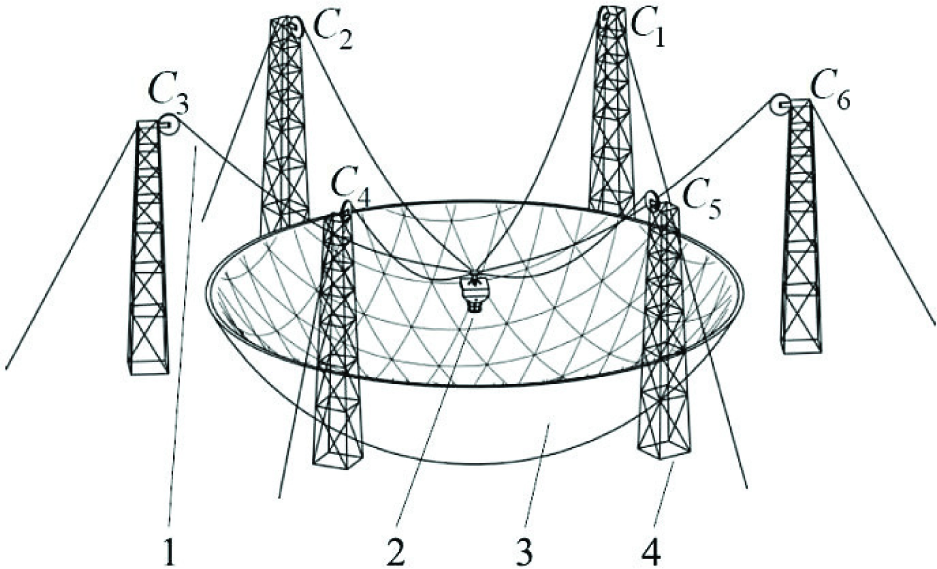
Structure sketch of the FAST. (1: cable-driven Stewart manipulator, 2: feed cabin, 3: active main reflector, 4: towers)

40m scale model of the feed cabin. (1: cables, 2: cable platform (end-effector of the cable-driven Stewart manipulator), 3: rigid Stewart manipulator, 4: A-axis of the A-B rotator, 5: B-axis of the A-B rotator, 6: framework, 7: end-effector of the rigid Stewart manipulator)
2.1 System dynamics
The entire dynamic model of the FSS, which is the basis for the simulation, is introduced here briefly, based on the independent dynamics of the rigid Stewart manipulator and the flexible cable-driven Stewart manipulator. The detailed derivation process can be found in the authors' previous work [18]. The inverse dynamics of the rigid Stewart manipulator with a fixed base can be expressed in the joint space as:

where
Moreover, considering each driving cable with a spring damping model, the dynamics of the cable-driven Stewart manipulator can be expressed in the workspace as:
where x represents the six-dimensional pose vector of cable platform, while ẋ and ẍ are velocity and acceleration vectors, respectively. The term MC (x) represents the inertia matrix, KC(x)is the elastic force, the cable damping force is included in the term VC(x,ẋ) and Fe is the external force.
When the rigid Stewart manipulator and the cable-driven Stewart manipulator are combined serially, the entire dynamic model of this FSPM can be represented as:

where
2.2 Control system structure
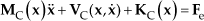
The control system for the 40m scale model of the FSS is shown in Fig.3 and is mainly composed of three controllers. The main controller is an industrial computer which provides the human-computer interface for operators, receives the feedback of total stations to calculate the terminal error and communicates with the cable manipulator controller and the feed cabin controller. According to the required tracking trajectory, the main controller generates the paths for the cable-driven Stewart manipulator and the A-B rotator based on the system kinematics. The cable manipulator controller consists of two Programmable Logic Controllers (PLCs) equipped with serial communication and digital-analogue conversion modules. Each PLC controls three DC servomotors, driving three cables. The feed cabin controller is also an industrial computer, equipped with the Turbo PMAC motion control card and located on the cable platform. The feed cabin controller is primarily responsible for the vibration control of the rigid Stewart manipulator based on the data obtained from the main controller. Besides, the feed cabin controller controls the A-B rotator according to the instructions of the main controller and sends back the cable forces measured with sensors. Considering the actual conditions, the RS-485 protocol is adopted for communication between the main controller and the cable controller. The User Datagram Protocol (UDP) is used for communication between the main controller and the feed cabin controller through a fibre optic cable.
Hardware structure of the FSS control system.
The vibration control task of the rigid Stewart manipulator controlled by the feed cabin controller is divided into two subtasks on two different levels. Fuzzy PID control is adopted on the upper level and used to decide the degree of compensation for the lower level in the joint space. The lower lever control is in charge of trajectory generation. Fine interpolation is completed by the Turbo PMAC card. Limited by the feedback frequency of the total station, the control cycle of the upper level is 0.1s (T1), while the control cycle of the lower level is 0.01s (T2). The constant-acceleration trajectory interpolation is applied on the lower level and uniform acceleration time is used. In order to minimize the reaction impulse of the rigid Stewart manipulator, the acceleration time equals the control cycle of the lower level.
3. Controller design
Due to simple structure, clear functionality and easy implementation, the PID controller has been widely applied in the industry. However, owing to influences of the time-variant, dynamic coupling and nonlinear factors inherent in the FSPM, it is hard to achieve the ideal performance of vibration control with the conventional PID controller. Besides, the PID controller is difficult and time-consuming regarding tuning parameters and adapting to a real operational environment. On the contrary, the fuzzy PID controller that can adaptively adjust PID parameters according to a fuzzy algorithm has been increasingly explored to solve engineering problems with high performance indexes.
In this section, the fuzzy PID controller, which combines the traditional PID controller and fuzzy logic, is designed to improve the terminal accuracy and system stability of the FSPM. The control configuration is shown in Fig. 4, where the fuzzy inference module is added to a PID controller in order to automatically adjust the proportional gain Kp, integral gain Ki and derivative gain Kd according to the error e(k) and the change of error ec(k). The fuzzy inference module includes two inputs and three outputs. These two inputs are e(k) and ec(k), while these three outputs are Kp, Ki and Kd. The fuzzy inference module can regulate three PID parameters based on the nonlinear mapping relationship of its inputs and outputs established according to the system dynamic characteristics and fuzzy set theory.

Block diagram of the fuzzy PID controller.
The fuzzy inference module is established on the basis of fuzzy set theory. Thus, the fuzzification of the input and output variables should be carried out first, which trans [0, 0.5]. For ease of design, they are respectively transformed into common normalized domains [−1, 1] and [0, 1]. Each input variable is assumed to take seven linguistic sets, defined as negative big (NB), negative medium (NM), negative small (NS), zero (ZO), positive small (PS), positive medium (PM) and positive big (PB). The fuzzy range of each output variable is separated into five semantic variables, such as small (SS), medium small (MS), medium (MM), medium big (MB) and big (BB). The corresponding fuzzy subsets can be described as

For the inputs, let ZO be the triangular membership function and the others are the Π-shaped membership functions. For the outputs, let BB be the trapezoidal membership function and others are the triangular membership functions. The full details of the membership functions are shown in Figs. 5 and 6.

Membership functions of e(k) and ec(k).

Membership functions of Kp, Ki and Kd
The key to realize the fuzzy PID control is to establish fuzzy control rules which greatly influence the control performance. Although a great number of expert systems and achievements have been obtained in the research into using fuzzy logic to adjust PID parameters adaptively, there is no systematic approach to design and check the fuzzy inference rules, input space partitions or membership functions at the present. In this paper, fuzzy control laws that focus on the stability and terminal accuracy of the FSPM are studied through numerical simulations and verified with model experiments which can reflect the dynamic characteristics of this FSPM. The proposed fuzzy control laws between inputs and outputs are summarized in Table 1.
Fuzzy rules

The max-min (Mamdani type) inference used to carry out fuzzy implication and synthesis calculations, is simple, effective and appropriate for a real-time control application. The centroid method is adopted to implement the defuzzification when output fuzzy sets are obtained.
4. Simulation and experiment
In this section, numerical simulations and physical experiments are carried out. The simulation parameters of the 40m scale model of the FSS are obtained from the detailed three-dimensional CAD model (shown in Fig.2) and adjusted from the actual measurement.
The numerical simulation focuses on the impact of wind disturbance. According to practical records, the maximum horizontal instantaneous wind speed is 8.1m/s at the location site of the 40m scale model. With the Bernoulli Equation, the wind pressure can be calculated from the wind speed and the air density. The wind force acting on the FSS equals the product of wind pressure and the effective area (2.2m2 for the 40m scale model). Then, the maximum horizontal wind force acting on the FSS can be figured out; about 100N. Based on the model analysis, the lowest vibration frequency of the FSS scale model is about 0.5Hz along the X-axis of the global frame. Thus, in order to test the effect of the vibration control the sinusoidal force with an amplitude of 100N (maximum wind disturbance) and the frequency 0.5Hz is used as the external disturbing force, exerted on the geometric centre of the feed cabin along the X-axis in the global frame. In order to emphasize the vibration control strategy a target pose is used instead of trajectory tracking. In the simulation, the initial state of the FSS is used as the target pose for convenience.
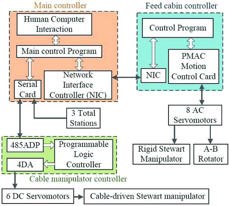
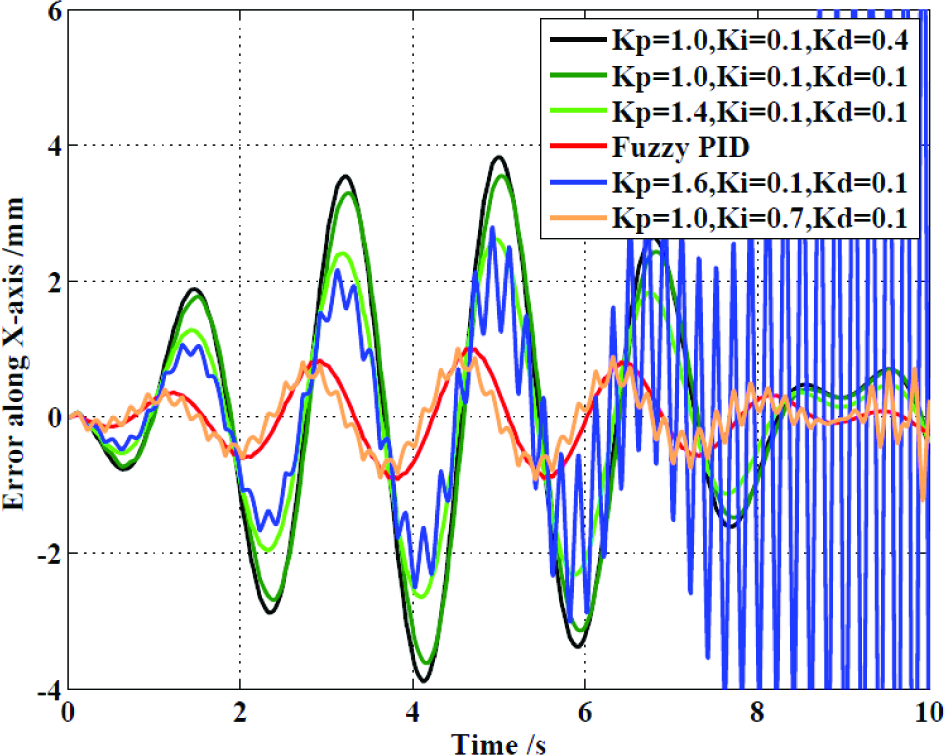
Simulation results are shown in Figs. 7 and 8, which illustrate that without vibration control the terminal error exceeds 10mm. After vibration control is carried out, the terminal error is reduced obviously. For the PID controller, the terminal error decreases gradually with the increase of Kp and Ki and decrease of Kd. However, high frequency vibration in the system terminal gradually appears which indicates that the reaction force generated by the compensation movement of the rigid Stewart manipulator disturbs the FSS. This unstable phenomenon reduces the terminal accuracy and could do damage to the rigid Stewart manipulator, such as, overloading the drive motor or overstepping the workspace. In general, it is difficult to solve the contradiction between terminal accuracy and system stability by using the conventional PID controller without considering the dynamic coupling of the FSPM. However, the fuzzy PID controller can realize the synthesis optimization, since it can adjust PID parameters according to the subject properties. As shown in Fig. 8, the results illustrate that the fuzzy PID controller can ensure good terminal accuracy and maintain system stability. Consequently, the proposed fuzzy PID controller is more effective than the traditional PID controller for the vibration control of the FSPM, when adopting the trajectory compensation strategy.
Terminal error without the vibration control.
Terminal error with PID and fuzzy PID controls.
The indoor experimental system is shown in Fig. 9. The feed cabin is hung under the bracket with short chains. This experiment focuses on the random disturbance caused by the movement of the cable-driven Stewart manipulator. The disturbance is exerted through the disturbance cable manually. The pose of the cable platform is measured by three total stations whose targets are uniformly arranged at the edge of the cable platform. The closed-loop poses of both the A-B rotator and the rigid Stewart manipulator are calculated in real time with encoder feedback from the servomotors. The practical terminal error is measured by a laser tracker, whose target is attached to the end-effector of the rigid Stewart manipulator.

Indoor experimental system. (1: slave computer, 2: targets of total stations, 3: master computer, 4: target of the laser tracker, 5: disturbance cable)
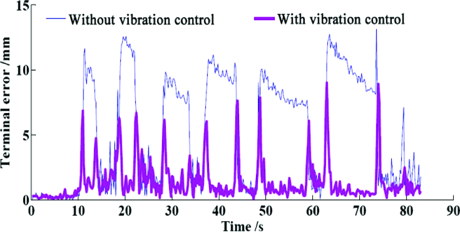
Figs. 10 and 11 are the experiment results adopting the PID and fuzzy PID controllers respectively. The terminal error without vibration control is calculated by assuming the rigid Stewart manipulator keeps still in its initial state. The terminal error is evaluated by the RMS value. As illustrated by the figures, since the trajectory compensation strategy is based on the tracking control, it can only reduce the already generated error; the terminal error of the FSS cannot be eliminated completely. However, it is obvious that the fuzzy PID controller can improve the terminal accuracy and ensure system stability for the FSPM when compared with the PID controller. This is because it can regulate PID parameters according to the terminal error and the error change automatically and reflect some dynamic coupling characteristics. The terminal error with the fuzzy PID controller is 1.61mm RMS and meets the accuracy requirement of 2mm RMS, while the RMS error of the conventional PID controller reaches 2.16mm. Besides, the fuzzy PID controller ensures better system stability. Unstable moments only appear in Fig 10, when the terminal error with the vibration control even exceeds the error without the vibration control. Therefore, the proposed fuzzy PID control can improve the vibration control performance of the FSPM.

Experimental results with the PID control.
Experimental results with the fuzzy PID control.
Ultimately, the suggested fuzzy PID controller based on the trajectory compensation strategy is adopted in the complete 40m scale model of the FAST to verify the overall system performance, as shown in Fig. 12. The FSS is programmed to track an astronomical observation trajectory at a linear velocity of 4.47mm/s. The maximum zenith angle of the designed trajectory is 30 degrees. The total run time is 5000s, the recording cycle of the position data is 0.1s and the maximum wind speed measured at the scene is 3.3m/s.
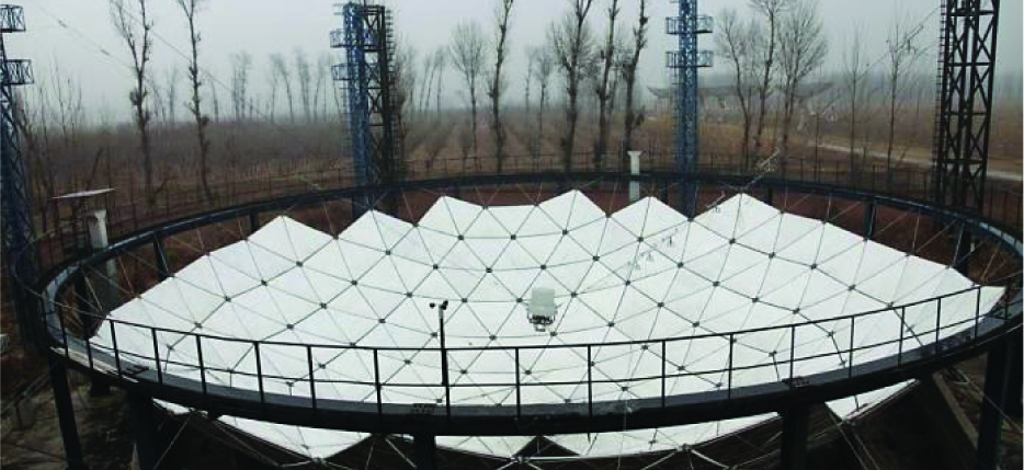
40m scale model of the FAST.
The terminal error of the FSS scale model under experimental observation is illustrated in Fig. 13.

Terminal error of the observation experiment.
In order to track a trajectory, the FSS needs to move to the starting point of the trajectory from its mechanical origin. During this time, the vibration control will not be carried out and the rigid Stewart manipulator is stationary. Thus, as shown in the figure, in the initial segment the terminal error exceeds 10mm. After implementing the vibration control, the terminal error decreases obviously. With vibration control the terminal error of the observation segment is 1.68mm RMS and meets the accuracy requirement of the FSS scale model for astronomical observations. The proposed fuzzy PID controller makes the FSS scale model meet both accuracy and stability requirements.
5. Conclusion
In this paper, the investigation of vibration control for the FSPM has been carried out, where the system dynamics are internally coupled and highly nonlinear. By taking the 40m scale model of the FSS as a subject, the fuzzy PID controller is developed and applied in the vibration control of this FSPM. Numerical simulations and physical experiments have been carried out respectively with the proposed fuzzy PID controller and the traditional PID controller. Results show that the proposed controller assures system stability and terminal accuracy at the same time, despite the time-varying and coupling of the FSPM. Further, the proposed controller offers several implementation advantages, such as: reflecting system dynamics with a limited computational burden, avoidance of unstable moments and better accuracy. Besides, the suggested control methodology is successfully adopted in the complete FSS scale model and the observation experiment verifies the feasibility of the future FAST prototype and provides great practical control experience. Consequently, the proposed control methodology can be further adopted in other FSPMs.
Footnotes
6. Acknowledgements
This research is sponsored by National Natural Science Foundation of China (No. 11178012, 51205224) and the State Key Laboratory of Tribology (No. SKLT11B06).