
Abstract
This paper proposes a vision-based autonomous move-to-grasp approach for a compact mobile manipulator under some low and small environments. The visual information of specified object with a radial symbol and an overhead colour block is extracted from two CMOS cameras in an embedded way. Furthermore, the mobile platform and the postures of the manipulator are adjusted continuously by vision-based control, which drives the mobile manipulator approaching the object. When the mobile manipulator is sufficiently close to the object, only the manipulator moves to grasp the object based on the incremental movement with its head end centre of the end-effector conforming to a Bezier curve. The effectiveness of the proposed approach is verified by experiments.
1. Introduction
The development of autonomous mobile robots operating in unstructured and natural environments has been studied extensively in robotics research. A mobile robot with a manipulator embraces mobile function and a high performance of operation, which is applicable in some challenging tasks such as cleaning of hazardous materials, transportation and rescue, etc [1]. Yamamoto and Yun present an algorithm to control the mobile platform so that the manipulator is maintained at a configuration which maximizes the manipulability measure, and simulation and experiment results verify its effectiveness [2]. In the follow-up work they study the effect of dynamic interaction between the manipulator and mobile platform [3]. In [4], Yamamoto and Fukuda propose an obstacle avoidance method for a coordinated task involving two mobile manipulators handling a common object, which is verified by simulation. [5] presents a task-oriented framework for dynamic coordination of mobile manipulator systems and studies the integration of mobility and manipulation, as well as cooperative manipulation. Platt et al. [6] introduce a refining sequence of controllers to solve the move-to-grasp problem, where controllers are defined in terms of controller goal regions and domains of attraction, and the approach is demonstrated by experiments. Sheng et al. [7] develop a neural network-based methodology for motion control of mobile manipulators subject to kinematical constraints and experiments on a 4-DOF manipulator arm illustrate the improved performance of the method. [8] addresses the trajectory tracking control of mobile manipulator by using robust neural network-based sliding mode control, where the neural network may overcome the disadvantage of fixed large upper bound of sliding mode control. Simulation examples are given to demonstrate the performance of the method.
On the other hand, vision is broadly recognized as one of most versatile sensors with its abundant information, low cost and agility for use. For numerous autonomous mobile robots, vision measurement and vision-based control are commonly used [1,9]. Traditionally, vision measurement has enabled industrial robotic manipulators to grasp and move objects in a structured environment with respect to a given trajectory [1]. Nowadays, more rich information such as position, orientation, shape, colour and pixel coordinates of the specified object may be acquired, which is beneficial for robotic manipulators executing the grasp operation in a more flexible manner. Seelinger et al. [10] develop a high-precision visual control method for mobile camera-space manipulation for unmanned planetary exploration rovers. It achieves a high level of positioning precision, which is robust to model errors and uncertainties in measurement. The method's performance is verified by experiments. [11] proposes a graph-based representation for the problem of door opening, which is demonstrated on the PR2 mobile manipulation platform. A vision-based robot manipulator is designed and implemented in [12], and the robot manipulator can draw a picture and pick up balls with the assistance of vision systems. [13] presents an autonomous mobile manipulator that can overcome inherent system uncertainties and exceptions by utilizing three technologies: coordinated base and manipulator control, combined visual and force servoing, and error recovery through flexible task-level control, which is demonstrated by a “peg-in-a-hole” task. Jain et al. [14] present the assistive mobile manipulator EL-E with a focus on the subsystem that enables the robot to retrieve objects from and deliver objects to flat surfaces.
Compared to the framework in which the image is captured by CCD cameras, a method widely used in mobile robot systems, the system where the image is captured by CMOS cameras and processed by embedded processors is compact, power-efficient and low-cost [15,16]. With the increasing complexity of tasks and environments, the miniaturized mobile robot with manipulation capability under some low and small environments is required. In this case, image capturing through CMOS cameras and embedded vision-based control provide a better solution.
The main contributions of this paper are summarized as follows. The visual information from CMOS cameras is processed in an embedded way to meet the manipulation demands for a compact mobile manipulator under some low and small environments. By the coordination between mobile platform and manipulator postures, the object is kept within the view, which ensures the smooth execution of the task. Also, the Bezier curve is introduced to plan the grasping movement of the manipulator for better manipulation.
The remainder of the paper is organized as follows. Section 2 gives the description of the problem. In Section 3, the embedded vision-based autonomous move-to-grasp approach is described. The experiments are presented in Section 4 and Section 5 concludes the paper.
2. Problem Description
In many situations, a mobile manipulator is required to search autonomously for objects scattered in unstructured environments. Once an object of interest is encountered and identified, the mobile manipulator will endeavour to get close to it and pick it up with an onboard robotic arm based on sensing information. In this paper, autonomous move-to-grasp based on embedded vision is considered for driving a mobile manipulator approaching a specified object, which will be grasped by the manipulator. In order to complete the task, two CMOS cameras and a 5-DOF robotic arm are equipped on a mobile platform, where a CMOS camera 2 is fixed in the end-effector of manipulator, as shown in Figure 1. Each camera with an OV9650 optical chip captures the image, which will be processed by a corresponding embedded processing board running at 400MHz.
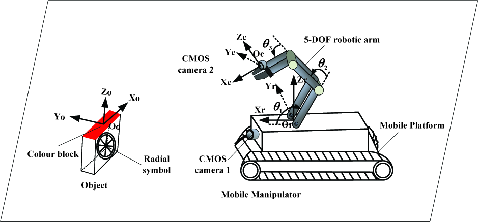
The move-to-grasp task for the mobile manipulator
Considering the size constraint of the compact mobile manipulator with embedded vision, the size of the object to be grasped is also small. From the viewpoints of environmental adaptability and better recognition from a farther distance, the object is endowed with a radial symbol with dual outer rings and a colour block on the top, which may satisfy the real-time computation requirement of an embedded processor. In Figure 1, OoXoYoZo is the object coordinate frame, OrXrYrZr is the mobile platform coordinate frame and OcXcYcZc is the coordinate frame of camera 2. θ1, θ2 and θ3 are pitch angles of shoulder joint, elbow joint and wrist joint, respectively. The remaining two joints are the roll joint of the wrist and the gripper joint.
3. The Autonomous Move-to-Grasp Approach Based on Embedded Vision
The move-to-grasp process may be decomposed into three stages: wandering randomly when the mobile manipulator cannot detect the specified object, moving close to the object after the object is observed and grasping with the manipulator. Firstly, the mobile manipulator wanders to search for the object. Once the object is observed by recognizing the radial symbol feature based on the information provided by CMOS camera 1, it means that mobile manipulator is a little far from the object and the information is extracted for guiding the motion of the mobile platform. When it acquires the feature of the colour block through the CMOS camera 2, the related information is extracted to control the mobile platform to go on approximating the object. Also, the posture of the manipulator is adjusted to keep the object within view. When the mobile manipulator moves sufficiently close to the object, the mobile platform stops moving and then the manipulator executes the grasping operation.
3.1 Object Recognition and Localization
The specified object is equipped with two features: a radial symbol with dual outer rings and a rectangle colour block. Next, the corresponding visual extraction processes are given.
3.1.1 Information Extraction Based on a Radial Symbol
The radial symbol with dual outer rings adopted in this paper is an extension of that in [17], which is shown in Figure 1. There are some spokes with a centrosymmetry property, and the spokes near the centre taper off from the exterior. In this part, we consider the monochrome symbol and the features are extracted from a grey image.
In order to identify the pixel coordinates of the radial symbol centre, we may firstly eliminate some irrelevant points according to its low brightness feature and the centrosymmetry feature of the radial symbol centre. Then according to the radial feature of the symbol, a spoke-based sparse template (take 15×15 as an example) is designed to detect the centre point, as shown in Figure 2, and only points marked “×” will be checked. These points constitute a set Ω. For a point Pc to be judged in the image, a 0-1 array is generated by binarizing the grey values of points in Ω corresponding to Pc. If the number of changes from 0 to 1 is similar to the number of spokes, the point Pc is considered as a candidate centre point. After filtering, we obtain the image coordinate (uc, vc) of the centre point by averaging the coordinates of all candidate points, and the average grey value ga of all candidate points is also calculated.

The spoke-based sparse template
After the radial symbol is identified, it is necessary to measure the distance between the optical centre of camera 1 and the symbol by detecting the diameter of the symbol in the pixel. We consider two circular arcs at the left and right sides of the symbol, and their edges are detected by a sparse template (take 7×3 as an example), as shown in Figure 3. Only points marked “×” will be checked. For point Parc in the curved edges recognition template, the grey values of three points marked “×” in the inner left circular arc are less than a given threshold Te, whereas the other three points marked “×” in the template corresponding to this arc have grey values that are higher than Te, where Te is related to ga. We illustrate the curved edge recognition process with the inner left circular arc. If there is a point on the left of the centre point with the same characteristics as those of Parc, it is recognized as the edge of the inner left circular arc. Similarly, we obtain the edge of the inner left circular arc and the distance dlp in pixel between it and the centre point of the symbol. Accordingly, the distance drp in the pixel between the edge of the outer right circular arc and the centre point is also obtained. Therefore, the diameter of the symbol in the pixel is expressed as dlp +drp. Based on the pinhole model, the distance between optical centre of camera 1 and the symbol is then given as follows.

Curved edges recognition template

where L is the physical diameter of the symbol and f indicates the focal length in pixel.
3.1.2 Information Extraction Based on Rectangle Colour Block
On the top of the object of interest, there is a rectangle colour block. Different from common edge extraction and the corner matching method, in this paper, we make use of features of the colour block image from the CMOS camera 2 to extract corners directly, and then corners are used to measure the pose of the object. For the case where the object is not observed fully, the centre coordinate values (up, vp) of the seen part on the image plane are obtained.
When the object is seen in its entirety, we firstly consider the projection image of the rectangle colour block shown in Figure 4(a) and the recognition templates in Figure 4(c) are adopted to extract four corners of the block. There are four templates corresponding to four corners, respectively, and we take the top-left corner recognition template (7×7) as an example. Only points marked “×” are chosen for judgment. The centre point (i, j) of the top-left template is considered as a corner only when the points (i, j) and (i+2,j+2) are colour points, and at most one of the two point sets (i−3, j−2: j+2) and (i+3, j−2: j+2) exists colour points, so does sets (i−2: i+2, j−3) and (i−2: i+2, j+3). The point with similar characteristics to that of the centre point in the top-left template is considered as a candidate top-left corner. After filtering, we obtain all candidate corners and the most top and most left point becomes the top-left corner. The bottom-left corner, top-right corner and bottom-right corner are also found in this manner.

Projection images of the rectangle colour block and the recognition templates; (a) Projection image of the rectangle block (b) Projection image of the rectangle block with deformation or rotation; (c) Corners recognition templates for (a); (d) Corner recognition template for (b)
Due to deformation or rotation, the projection image of the rectangle colour block changes (see Figure 4(b)) and the corner recognition templates in Figure 4(c) become invalid. In this case, we consider the template with adaptive size adjustment, as shown in Figure 4(d). Only points marked “×” are to be judged. The centre point (i, j) of the template is considered as a candidate corner if (i, j) is a colour point and the proportion of the number of colour points to that of all marked points is within a certain range. All points satisfying the characteristics of the centre point (i, j) constitute corner candidate set Sc. After the four point clusters corresponding to four corners of the rectangle colour block are obtained by clustering according to the distribution of points in Sc, four corners are extracted based on the relative positions of these four clusters.
Based on the four corners extracted from the CMOS camera 2, the position of the centre point of the colour block P (px, py, pz) relative to frame OcXcYcZc is obtained according to the physical size of the rectangle colour block, the camera model [22] (see Eq. (2))as well as the shape constraint-based pose measurement proposed by Xu et al. in [18].

where (u0, v0) is the image coordinate of the intersection point of the optical axis centre line and the image plane; kx and ky are the amplification coefficients of x-axis and y-axis direction, respectively;(xc, yc, zc) and (xt, yt, zt) are the coordinates of a point in OcXcYcZc and OoXoYoZo, respectively; (u, v) is the image coordinate of the point; and R3×3 is the rotation matrix. Intrinsic parameter array Min is calibrated using the Matlab calibration toolbox [19].
3.2 Motion Control of Mobile Platform and Posture Adjustment of the Manipulator
The mobile platform is responsible for carrying the manipulator to a suitable grasp zone and its decision is autonomously made based on the extracted object information from CMOS cameras 1 and 2. In addition, during the approaching process based on camera 2, the manipulator has multiple varying postures, such as posture 1,…,posture n, as shown in Figure 5. The postures of the manipulator are switched according to Xor, where (Xor, Yor,Zor) is the position of point Oo in frame OrXrYrZr. By the coordination between mobile platform and manipulator postures, the object is kept within the view of the CMOS camera 2.

The posture adjustment of the manipulator when the mobile platform approaches the object
Initially, the mobile platform moves randomly in the environment, and no camera sees the object. Once the object is observed by camera 1, the mobile platform adjusts the motion based on the image coordinate (uc, vc) of the centre point of the radial symbol and the distance D between optical centre of camera 1 and the symbol. The speed difference between left and right tracks is set to k1 · arctan(vc − v0)/ D , where k1 is a constant. When camera 2 sees the object in its entirety, the mobile platform adjusts its motion based on the position of point Oo in frame OrXrYrZr. The speed difference between left and right tracks is set to k2 · arctan Yr o /Xro′, where k2 is a constant.

where Hrc and Rcr represent the homogeneous transformation and rotational matrix of frame OcXcYcZc to frame OrXrYrZ, respectively, dcr =[dx,dy,dz] T is the position vector of Oc in frame OrXrYrZr.
When part of the rectangle colour block is seen by camera 2, the mobile platform adjusts its motion according to Xor and the coordinate(up, vp). When vp is approximately at the middle of the image in v-direction, the mobile platform moves ahead, otherwise, it only turns with the direction being related to vp. Specifically, when Xor is small, the mobile platform only turns when vp is approximately at the middle of the image in v-direction and it turns at a little angle with the direction being related to vp in other cases. When the object is out of sight of camera 2, the mobile platform will move according to the previous decision.
3.3 Vision-Based Manipulator Grasp Control
The mobile platform stops when it reaches the suitable position, i.e., when the specified object is in the workspace of the manipulator. Combined with object information provided by the CMOS camera 2, the grasping operation is executed with point Ep conforming to the trajectory planned by the Bezier curve according to the coordinates of Ep(XrEp, YrEp, ZrEp) and the object in frame OrXrYrZr, where Ep is labelled as the head end centre of the end-effector.
We consider the case where the manipulator grasps the object from its top with its posture returning to posture 1 for better manipulation. The cubic Bezier curve [21] is employed to plan the trajectory of Ep, which is given as follows.

where qi(i=0,1,2,3) are the coordinates of four control points of the curve and they are determined according to the coordinates of (Xor, Yor, Zor) and (XrEp, YrEp, ZrEp) in the initial grasping posture; Bi,n(t) is Bernstein basis polynomial. The Bezier curve is discretized into a series of sub-goal points for actual planning.
In order to ensure that the point Ep moves along the trajectory generated by the Bezier curve, the dynamic step angle-based incremental movement presented by Ning et al. in [20] is used. For our 5-DOF manipulator, only the pitch angles of the shoulder joint, elbow joint and wrist joint are responsible for the position of point Ep. The lengths of the linkages corresponding to these three joints are labelled as Lp(p1,2,3). The position of point E
p
relative to frame OrXrYrZr can be obtained by

with YrEp as a mount-related constant.
The pitch angles may be adjusted according to θp(t + 1) = θp(t) − αp(p = 1,2,3) when θp(t) − αp is within [θp min, θp max], and it remains unchangeable in other cases [20], where θpmax and θpmin are the upper and lower limits of joint angle θp; αp =λ x [Gxp (θp)+δzGzp(θp)] is the dynamic step angle; λp is a given positive constant related to the structure of the manipulator; Gxp(θp) and Gzp(θp) are the gradients of angle θp along x-axis and z-axis directions of frame OrXrYrZr, respectively;δx and δz are the deviations between point Ep and next sub-goal point in x-axis and z-axis direction. Figure 6 gives a motion simulation of the manipulator with the head end centre of the end-effector along a trajectory generated by the Bezier curve.
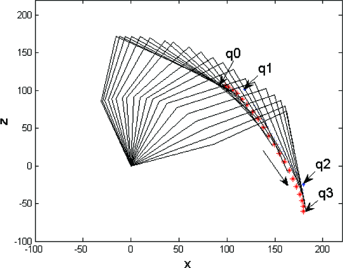
The motion simulation of the manipulator based on the Bezier curve
4. Experiments
The proposed move-to-grasp approach for the mobile manipulator is verified by experiments. The parameters of the approach are as follows. k1=44, k2=52,λ
p
=3.5e−5. Intrinsic parameter array is
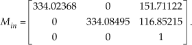
The lengths of linkages corresponding to the shoulder joint, elbow joint and wrist joint are 91mm, 88mm and 132mm, respectively. L=114.8mm, f =672pixel. In the following experiments, we consider there are three postures for the manipulator and n=3.
In experiment 1, the mobile manipulator executes a short-range move-to-grasp task. The selected images are shown in Figure 7, where the upper three images display the posture variation of the manipulator during the approaching process and the lower three images describe the grasping process while the mobile platform is stationary.
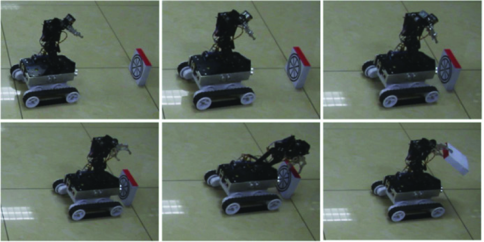
A short-range move-to-grasp operation
Experiment 2 considers the case of a static object under a table and the move-to-grasp process is shown in Figure 8. Figure 9(a) gives the state transition diagram for the approaching process and the five states are considered for better description. The first two states are wandering randomly (m-state=1) and approaching based on information from camera 1 (m-state=2). The other three states are approaching based on information from camera 2 with posture 1, posture 2, posture 3 of the manipulator, which correspond to m-state=3, 4 and 5, respectively. The motion trajectory of the mobile platform is shown in Figure 9(b). From the experimental results, we can see that the mobile platform with the manipulator begins to execute the task from position S and it approaches the specified object after the object is observed. The posture of the manipulator is adjusted to meet the requirement of observation. When the mobile platform stops at position G, the manipulator begins to grasp and finally the task is completed.

Move-to-grasp operation for a static object under a table

The results of experiment 2; (a) State transition diagram for the approaching process; (b) Motion trajectory of the mobile platform
In experiment 3, the object is dragged manually and the selected images are shown in Figure 10. The state transition diagram for the approaching process is shown in Figure 11(a) and the motion trajectories of the mobile platform and the object are shown in Figure 11(b), where Sr, Gr are the starting and ending positions of the mobile platform, and So and Go are the starting and ending positions of the object. It is seen that the mobile manipulator may adjust itself with the motion of the moving object. After the object stops at position Go, the mobile manipulator continues to approach the object and the object is picked up smoothly.

Move-to-grasp operation for a moving object

The results of experiment 3; (a) State transition diagram for the approaching process; (b) The motion trajectories of the mobile platform and object
5. Conclusions
This paper has studied an autonomous move-to-grasp operation based on embedded vision for a compact mobile manipulator with two CMOS cameras. The specified object is marked with a radial symbol and a rectangle colour block for recognition and localization. The mobile manipulator adjusts itself to approach the object by vision-based control. By combining the incremental movement method, the manipulator grasps the object with its head end centre of the end-effector moving along a Bezier curve. Experiments have been implemented to verify the effectiveness of the proposed approach. The ongoing and future work includes obstacle avoidance of the mobile platform as well as better coordination between the manipulator and the mobile platform.
Footnotes
6. Acknowledgments
This work is supported in part by the National Natural Science Foundation of China under grants 61273352, 61175111, and in part by the National High Technology Research and Development Program of China (863 Program) under grant 2011AA041001.