
Abstract
In this paper, an improved robust vector control strategy is designed to drive the Permanent magnet synchronous motor in a wide speed range mode. The designed control method guarantees the precision and robustness of speed regulation performance by using recurrent neural network architecture. The stator current controller parameter tuning problems, which characterize this control strategy, are resolved using a bacterial foraging optimization algorithm to find the optimal parameters of the current controllers used. A field weakening control algorithm generates an adaptive magnetizing current command to achieve the desired high speed mode. The robustness and effectiveness of the global control scheme are verified through computer simulations established under a Matlab-Simulink environment.
1. Introduction
Robotics has been of interest to mankind for many years. Nowadays, the use of robots is wide-spread in the manufacturing industry, the military, space exploration, transportation and medical applications. A consideration of performance robustness, rapidity and precision is required for many of these applications. An autonomous car can be considered as robotic or self-driving [1]; an electrical vehicle can be used in this robot application [2] for its efficiency, simplicity and ease of maintenance, and especially for its role in environmental protection. Recent research has therefore focused on studies of these vehicles to improve drive performance.
Many electrical motor types are used in these vehicles. Zhu [3] made a comparative study on these electrical machines and drives. In his approach, induction machines, switched reluctance machines and permanent magnet synchronous motors are compared. The obtained results prove that the permanent magnet synchronous motor is more efficient than the other types.
Based on this motor type, much control research has sought to ensure a high speed control phenomenon. Several control strategies have been proposed and tested for controlling this device, such as vector control or direct torque control, as presented in [4], [5] and [6]. The fast torque, speed responses, and especially the simple architecture make the vector control strategy most popular in these applications; however, the robustness problems are already present in this strategy, especially under motor parameter variations.
Various solutions have been suggested for these problems. The main idea is to change or replace the three commonly used PI controllers by neuron network, fuzzy and neuro-fuzzy controllers, as presented in [7], [8], [9] and [10], or controllers characterized by robustness, as in the IMC or MRAC methods presented respectively in [11] and [12]. The efficiency of the neural network approach has been proven, as well as its robustness and precision in various applications, as presented in [13] and [6]. Therefore, this technique is implemented in this application to increase the system outer loop control performance.
In this work, we seek to build a robust PMSM control loop which can be operated in a wide speed range and which is useful in relation to the problems that can appear in this speed region with PMSM parameters variations due to external effects as high temperatures, vibrations or dust. To resolve this problem, the recurrent neural network has proved advantageous and has been used to replace the conventional PI speed controller.
The other two current controllers used are characterized by their parameter tuning problems. These values can influence system robustness and efficiency, and optimum PI parameters are therefore of the utmost importance. Many methods are presented in the literature to find these values, such as particle swarm optimization (PSO) [14]-[15] and bacterial foraging optimization (BFO) [16] algorithms. In [17], the author proves the precision of BFO; we have therefore used this method to adjust the desired current's PI parameters.
As this application needs a high speed running mode, the field weakening operation is implemented based on Morimoto's approaches presented in [18] and [19].
Consequently, the obtained new control scheme is implemented in the MATLAB/Simulink environment and tested in a wide speed range. Robustness tests are executed to verify the system performance.
This paper is organized as follows. After a general introduction, the second section describes the proposed high speed algorithm (HAS). The recurrent neural network speed controller architecture is given in the third part. The bacterial foraging optimization algorithm is described in general terms in the fourth part, and the simulation results are then presented and discussed. Finally, the conclusion is presented.
2. High speed algorithm
The establishment of the high speed control algorithm is based on the PMSM mathematical model. The dynamic properties of a PMSM can be described by a set of nonlinear differential equations linking the stator currents and voltages with the mechanical quantities torque, speed and angular position. These mathematical expressions can be formulated as in Eq (1) and Eq (2), which present, respectively, the stator voltage and the electromagnetic torque expressions in the rotating (d, q) reference frame. The mechanical expression can be written as presented in Eq (3) [14].


and

In the PMSM, the flux is mainly produced by the rotor side magnet and denoted λm. In the field-oriented control strategy and within the rated speed regime, the direct stator current id is maintained equal to zero. However, to go beyond the rated regime, the total flux is minimized following the field weakening strategy (FW).
The direct stator field component depends principally on the direct stator current, stator inductance and the mainly permanent magnet flux. However, the quadrature element depends on the quadrature stator current, which is generally introduced by the electromagnetic torque demand. Therefore, to minimize the total flux, it is evident that the direct component flux must also be minimized. This occurs if the direct stator current goes to the negative region (
Therefore, the field weakening principle is described in Fig. 1, which presents three zones. The first gives the current limitation as described in the first part of Eq (4). The second is the ellipse form given to the voltage limitation, as indicated in the second part of Eq (4). The field weakening region is illustrated by the hatched area in the circle, which designs the interconnection between the two last zones. Generally, the current limitation circle is centred on zero and its radius depends on the inverter maximum current. Whether the limitation voltage shape is an ellipse is dependent on
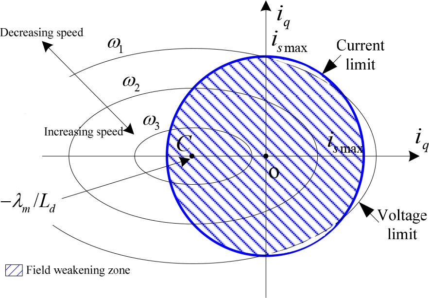
Field weakening operation under inverter voltage and current limits


where

The direct reference stator current is:

3. Recurrent Neural Networks Speed Controller
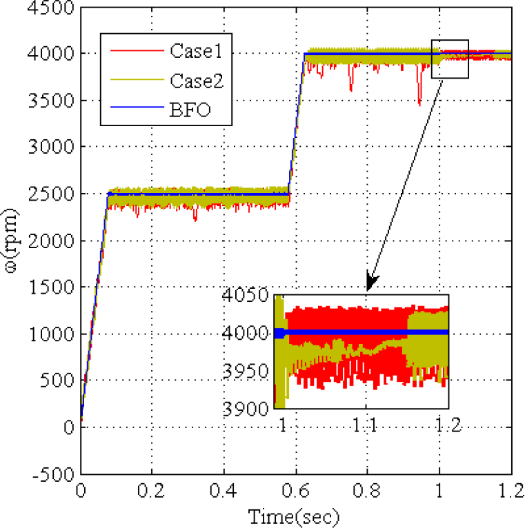
Recurrent neural networks (RNN) have been an interesting and important part of neural network research since the 1990s. Much architecture is presented in the literature, characterized sometimes by total connection and sometimes by partial connection. In this work, the recurrent neural networks speed controller (RNNSC) is proposed and its architecture is given in Fig. 2. The structure corresponds to three neurons at input layer, two neurons in hidden layer and one in output layer. Sj represents the input signals of the hidden layer, X is the output signal of the hidden layer, iq* is the final output signal of the RNNSC and Ii(k) is the input vector. Wj,jD(k) is the weight between the same neuron in the hidden layer, Wj,jL(k) is the weight between two successive neurons in the hidden layer, Wj,iI(k)is the weight from the input layer to the hidden layer and WjO (k) is the weight from the hidden layer to the output layer. The sigmoid activation function is used in the two first layers and the linear function on the output layer.

Recurrent neural network speed controller architecture
The mathematical relations between the different neurons in the different layers are given by Eqs (7), (8) and (9):


The gradient method is used to adjust the weights and the mathematical expressions can be presented as in Eq (10).. More details are given in [14].
η represents the RNNSC learning rate.

After the training process, using the database presented in Fig. 3 it can be evaluated whether the RNNSC is then able to achieve the desired speed. In this case and for 200 learning epochs, the obtaining learning error is approximated as equal to 1.10−10. This last is sufficient enough to be relied upon in the designed RNNSC.

Learning database for the RNNSC
4. Bacteria Foraging Optimization: A Brief Overview
Many theories for solving the optimization problems have been presented in the literature, such as the particle swarm optimization and genetic algorithms [17]. All these methods are derived from the context of natural behaviour and environment. In bacteria behaviour law, all the elements support the species with the best ability to search for food and eliminate others. Three processes characterize this algorithm as presented in [21] and in [21] Passion gives the corresponding optimization theory method.
The bacterial foraging optimization algorithm is illustrated in Fig. 4. J(i, j, k, l) denotes the function cost value and θi(j,k,l) the i-th bacteria position. In the present algorithm, the most important loop is the chemotaxis, designed by “B”. Here, each bacterium passes through the tumbling and swimming step “F”, where the corresponding objective value will be calculated and compared to the less one saved one. After making sure that all the bacteria, “G”, are executing the entire chemotaxis step, “B”, reproduction begins; i.e., the half with the highest objective function cost dies, while the half with the lowest cost function divides. The location of the obtained copies is the same as their parent. After reproduction, “elimination-dispersal” begins. With a probability Ped, elimination and dispersion occurs for each bacterium (this keeps the number of bacteria in the population constant) [21] and [22]. The elimination and dispersal events assist chemotaxis progress by aligning the bacteria with the nearest required values. Each bacterium, according to a fixed probability, is dispersed from its original position and moves to the best position within the search space. These events may prevent local optima trapping but lead to disturbance of the optimization process.

A global diagram of the Bacterial Foraging Optimization algorithm
In the chemotaxis step, the bacterium is said to be swimming if it moves in a predefined direction, and tumbling if it moves in an altogether different direction. The bacterial position is updated mathematically by Eq (11).

5. Simulations And Results
To verify the effectiveness of the proposed high speed PMSM control algorithm, a digital simulation based on the Matlab/Simulink software package has been carried out. The PMSM characteristics are given in Tab. 2.
PMSM parameters and rated values

The entire proposed control scheme, built as connected subsystems, is illustrated in Fig. 5. The first subsystem is the recurrent neural network speed controllers (RNNSC) used for online generating the quadrature reference stator current iq*. The high speed algorithm is used for online generating the direct reference stator current id*. Once the reference and actual quadrature stator currents have been compared, the PI-QSC controller will generate the quadrature reference stator voltage vq*. A PI-DSC is used for the d side to generate the direct reference stator voltage vd*, as a response of the processed direct stator current error as a controller input signal. Park and Clark transformations are added to build the three corresponding reference voltages, vA*, vB* and vC*.A Pulse Width Modulation (PWM) subsystem is driven by the voltage source inverter feeding the PMSM.

Block diagram of the proposed robust high speed PMSM control scheme
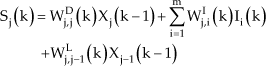
Fitness cost and PI parameter evolution: (a) fitness cost function for the DSC case, (b) fitness cost function for the QSC case, (c) and (d) PI-DSC parameters, (e) and (f) PI-QSC parameters
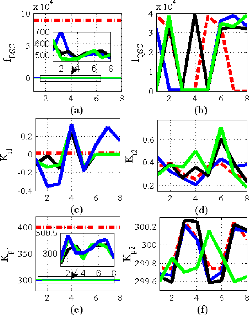
After obtaining the speed controller architecture, the remaining control problem is with the PI current controller's parameters, which must be given. In this control scheme, these PI parameters are established by trial and error in two different cases, as presented in Tab. 1. The influence of these PI parameters, first on the direct and quadrature stator current responses and then on the speed behaviour, is clearly shown in Fig. 7, Fig. 8 and Fig. 9. There is clearly a large oscillation in the reported signals. The stator current components' worst control deteriorates the PMSM regulation performances and power efficiency. This is of great importance in robots' electric drive systems. Therefore, in order to minimize these oscillations, an intelligent optimization method based on the BFO architecture is performed here, in order to help in adjusting these PI-DSC and PI-QSC parameters for a high-performance PMS drive.

Direct stator current results with three PI-DSC parameters tuning

Quadratic stator current results with three PI-QSC parameters tuning
Effect of PI-DSC and PI-QSC parameters on the speed results
PI-DSC and PI-QSC parameters

The BFO tuning algorithm needs to start with data such as: bacteria number: s = 8, chemotaxis steps number: Ne = 4, swim length: Ns = 4, reproduction steps number: Nre = 2, elimination-dispersal events number: Ned = 2, number of bacteria reproductions (splits) per generation Sr = s/2 and the probability that each bacteria will be eliminated/dispersed: Ped = 0.25. Also: run length c(:, 1) = 0.05 * ones(s, 1). The initial PI-QSC and PI-DSC parameters [Kp1, Ki1, Kp2, Ki2] are randomly chosen and the desired fitness function is presented in Eq (12). Here, the integral square error ISE method is used and α1=β1=100.
While the algorithm runs, the “s” bacteria search for the best positions, i.e., those with the minimum of fitness cost. These positions will be transferred to the other bacteria so that they adjust their own places. At the end of the iterations, the obtained positions, which are equal to the minimum cost function, are chosen as the PI-DSC and PI-QSC proportional and integral parameters.
It is important to indicate that, normally four cases would be shown, because there are two reproduction steps and two elimination steps. Here, for each elimination phase there are two reproduction steps, as shown in Fig. 6,. Four colours are shown in the diagram, each corresponding to a chemotaxis step for the bacteria.
Fig. 6 shows the evolution of the fitness function cost and the corresponding PI parameters proportionally to the bacteria number. The case of the PI-DSC tuning parameters is presented in Fig. 6a,Fig. 6c and Fig. 6e; the first presents the cost fitness function and the others present the integral and the proportional PI-DSC gain coefficients, respectively. The case of the PI-QSC tuning parameters is illustrated in Fig. 6b,Fig. 6d and Fig. 6f.
For the case of the PI-DSC tuning parameters, the best fitness cost function corresponds to the green colour for bacteria number two, where the corresponding PI parameters are shown in Tab.1.
In the PI-QSC case, there appears to be a strongly unstable and oscillating fitness cost signal response (Fig. 6b). The BFO algorithm fails to give optimum values for all the bacteria used. However, some of these particles, such as the bacteria number three, four and five, reach the best positions. These positions are chosen and used as PI-QSC tuning parameters. It is important to note that these positions will be the target for the other bacteria after more running time, and after the reproduction and elimination steps number in the BFO architecture has been modified.
After these new PI parameter values are applied in the global control algorithm, the novel stator currents results are obtained, which are illustrated in Fig. 7 and Fig. 8. These show good performances, especially when a stator resistance variation is applied at t=1sec in the high speed region. These results prove the current stability in this speed zone and the effectiveness of the BFO algorithm in torque ripple minimization. The efficiency of this algorithm is also shown in the speed results presented in Fig. 9, where the oscillations are minimized.
Once the desired speed controller is designed and the optimum PI-QSC and PI-DSC parameters are tuned, the global control scheme performances will be tested in relation to robot trajectory and drive tracking. A wide speed range is considered, with the appliance of the PMSM load torque dynamics and parameter variations.
The applied target variable speed is changed at 0 rpm to the rated value (2500 rpm), then from the rated value to a high speed of 4000 rpm. In this case, the load torque applied to the motor is in the context of realistic behaviour of a constant power high speed regime, where, the load torque decreases if the desired speed exceeds the rated one. Abrupt load torque variations of 0.1 N.m are also added and removed several times. The motor working regimes imply parameter variation, which mainly consists of stator resistance variations. At 1 second a rise of 100% of stator resistance is introduced as an abrupt variation.
As previously cited, the first robustness test is carried out for load torque variations. Fig. 10 shows the speed behaviour results. The load torque dynamics appliance is given as:

Speed behaviour results with variation of stator resistance and load torque
At rated speed range:
At t1=0.15s, Tl(t1)=Tlrated+0.1
At t2 =0.22s. Tl(t2)= Tl(t1)-0.1
At high speed range:
At t3=0.8s, Tl(t3)= Tlmin +0.1
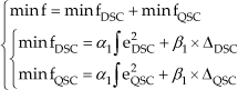
The obtained speed and stator current results shown in Fig. 1a and Fig. 11 verify the robustness of the proposed high speed control algorithm. The PMSM parameters are highly sensitive to the motor operation regime conditions, which induce a high temperature or hard vibration. Therefore, the robustness of the proposed control scheme against these variations is required. The application of a stator resistance variation in the high speed mode is appropriate, and the system behaviour is verified. This PMSM parameter variation is applied at t=1s, as indicated above. The effectiveness of the proposed high speed PMSM vector control architecture is verified and highlighted in the speed zooms shown in Fig. 10, and illustrated by the stator current results in Fig. 11.
Stator current results with variation of stator resistance and load torque
5.1. Field weakening results (HSA):
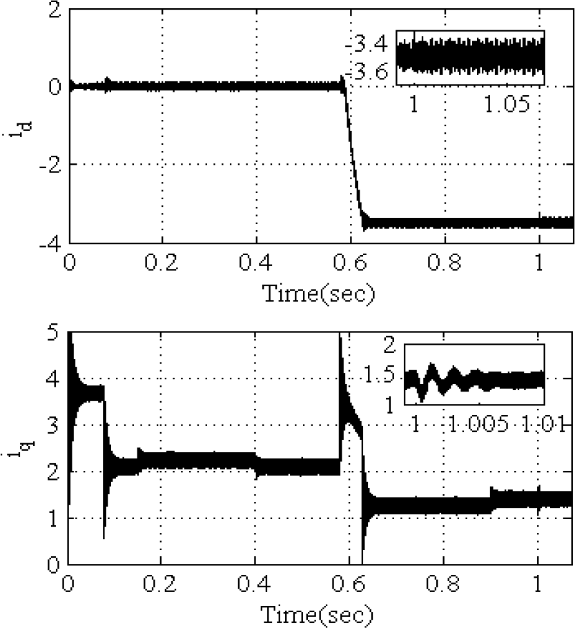
As presented in Fig. 10, two speed regions are obtained. From t=0sec to t=0.58sec, the rated speed zone is illustrated: it is clear that the direct stator current in Fig. 11 is equal to zero. However, if the desired speed exceeds the nominal one for the high speed zone, changing from t=0.58sec to t=1.2sec, the direct stator current command is reduced to the negative region. The field weakening principle can be simultaneously shown from the direct stator current and the flux dynamic results. The flux magnitude is reduced and moves towards the weakening regime in terms of circle radius, as presented in Fig. 12.
Stator flux trajectory
In the stationary frame “α, β”, the stator flux trajectory can be proven by the circle radius presented in Eq (13). If the direct stator current id is reduced in the high speed case the circle radius will be minimized to R2.

6. Conclusion
This paper has outlined a robust PMSM control design, based on recurrent neural network and the BFO algorithm. In this application, the used motor must be operated in a wide speed range and especially in the high speed mode. For this purpose, a global control and high performance drive scheme has been built and described. Based on the robustness of the recurrent neural network, the vector control strategy is modified, whereby the conventional PI speed controller is replaced by a recurrent neural architecture.
This study has demonstrated the importance of the two current controllers used in this control strategy in terms of the system performance. To improve drive characteristics, an intelligent optimization method based on the BFO algorithm has been designed for tuning the direct and quadrature stator current controllers. The importance of this algorithm is clearly shown on the stator current and on the speed behaviour results.
In the robustness study, the global control scheme proved its efficiency in two different tests. In the first, a load torque was applied in rated and high speed modes. The second test investigated the robustness of the control schemes when the stator resistance of the PMSM was varied.