
Abstract
Super low altitude remote sensing satellites maintain lower flight altitudes by means of ion propulsion in order to improve image resolution and positioning accuracy. The use of engineering data in design for achieving image positioning accuracy is discussed in this paper based on the principles of the photogrammetry theory. The exact line-of-sight rebuilding of each detection element and this direction precisely intersecting with the Earth's elliptical when the camera on the satellite is imaging are both ensured by the combined design of key parameters. These parameters include: orbit determination accuracy, attitude determination accuracy, camera exposure time, accurately synchronizing the reception of ephemeris with attitude data, geometric calibration and precise orbit verification. Precise simulation calculations show that image positioning accuracy of super low altitude remote sensing satellites is not obviously improved. The attitude determination error of a satellite still restricts its positioning accuracy.
Keywords
1. Introduction
Remote sensing of the Earth by observation satellite systems has been an important means of obtaining information of our aerospace. For a long time the geometric correction of remote sensing images has required sufficient uniformly distributed Ground Control Points (GCP). However, this is dependent on extrapolating the parameters of the satellite and a crucial task for the geometric correction of an image is to calculate the image position accuracy of the GCPs. SPOT-5 [1], IKONOS [2], QuickBird [3] and ALOS [4] are some of the current commercial international high resolution remote sensing satellites. Their position accuracy is increased to about 20m using a recursive ephemeris estimator in the case of no GCPs.
Image positioning accuracy is determined by the degree of correction required for imaging data and engineering data of a remote sensing satellite system to integrate into the world index. Some of the parameters involved are: orbit determination accuracy of the satellite, attitude determination accuracy, camera exposure time, synchronizing the precise time of receiving the ephemeris and attitude data, geometric calibration and precise orbit verification [5,6]. Most of the available literature studies position processing and the positioning accuracy analysis of remote image acquisition but, the design of high-precision positioning and high resolution optical remote sensing is not often mentioned.
Furthermore, remote sensing satellites moved on orbits above 500km in the past. So imaging quality was limited by the camera focal length, CCD pixel size and the satellite mass, volume and power. Imaging resolution was hardly beyond the order of meters [7]. Solar electric propulsion technology has been approaching perfection since the first GOCE satellite was launched in 2009. This satellite is kept in a lower orbit to improve remote sensing image quality. This is implemented by compensating for atmospheric resistance effects with drag-free control. Now some related aerospace agencies are paying more attention to super low altitude flight: British SEA Company is considering designing a 160×400km spacecraft (called Skimsats) to be used for optics or SAR (synthetic aperture radar) imaging [8]. This could raise imaging resolution and make savings for the star-earth link budget; Japan's Super Low Altitude Test Satellites (SLATS) plan to test the attitude hold of ion propulsion and micro propulsion and the protection from oxygen ion erosion on the satellite surface by developing a satellite to orbit at an altitude of 200km [9]. XU demonstrates satellite system programs taking imaging resolution as their target and designs a work mode for each subsystem. The configuration parameters of related parts are acquired by applying multidisciplinary design optimization to the satellite volume, mass and power index [10].
This paper uses engineering data on the imaging positioning accuracy of satellites combined with the system design program of super low orbit remote sensing satellites. The exact line-of-sight rebuilding of each detection element and this direction precisely intersecting with the Earth's elliptical when the camera on the satellite is imaging, are ensured by the joint design of key parameters. These parameters include: orbit determination accuracy, attitude determination accuracy, camera exposure time, accurately synchronizing the reception of ephemeris with attitude data, geometric calibration and precise orbit verification. Precise simulation calculations show that the image positioning accuracy of super low altitude remote sensing satellites is not obviously improved. The attitude determination error of a satellite still restricts its positioning accuracy.
2. The System Design of Super Low Altitude Remote Sensing Satellites [10]
We design the satellite in a six-sided prism configuration, the digital antenna and solar array both require unfolding mechanisms. A super low orbit is a sun-synchronous orbit when the descending node local time is 10:30AM. A three-dimensional remote sensing imaging mission requires an altitude of 200km; a two-dimensional remote sensing imaging mission requires an altitude of 180km. Ion propulsion requires a large amount of power for orbit maintenance and the solar wing should be able to turn about 20 degrees about its axis of rotation due to the annual change of the signed angle of the vector to the Sun relative to the orbital plane.
The main loads of satellite are: the fixed solar array wings, the stars solar array, the stabilizer fin, the gravity gradiometer, the ion propulsion unit, the S-band antenna, the GPS/GLONASS antenna, the GPS/GLONASS receiver, the Laser Retro Reflector (LRR), the attitude control system and the ASTRO10 star sensor. Satellite configuration is shown in Figure 1. The drag-free control and attitude control systems are composed of following sensors and actuators: (1) A pair of ion propulsion units, used to compensate for atmospheric drag in a direction tangential to that of the satellite orbit; (2) 8 micro-propulsion units, used to compensate for the drag of the attitude tracking and orbit non-conservative forces. (3) A gravity gradiometer, used to measure linear acceleration and angular acceleration. (4) 2 GPS receivers, used to reference the positional posture and velocity of the satellite's centre of mass; these can also be used for the precise determination of the orbit of the satellite.

Configuration diagram of satellite in orbit
The design of the orbit's semi-major axis is biased in order that the descending node local time coincides with the attenuation of the super-low-orbit altitude and a subsystem test is implemented in orbit. The maximum thrust and the measurement of acceleration feedback are designed for aerodynamic drag compensation in orbit. An altitude plan during orbital flight is shown in Figure 2.
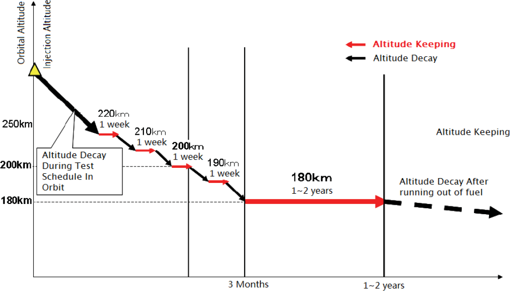
Altitude plan for a super low altitude satellite during in-orbit flight
3. The Design of Satellite Engineering Patameters for Image Positioning
3.1 Image positioning principle
If the flight direction is x, the line-of-sight

where Schematic diagram of imaging positioning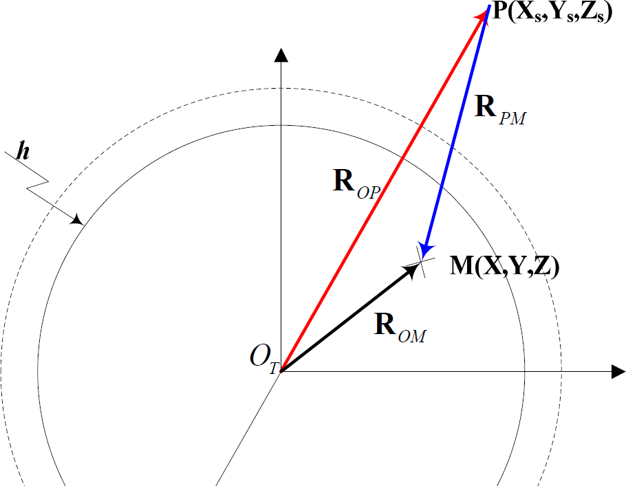

where [XS, YS, ZS]T is the location of the satellite in a WGS-84 coordinate system during imaging, λ is the imaging scale, [X, Y, Z]T is the position of intersection with M.
3.2 The design of the satellite engineering parameters
The line-of-sight vector for each detection element consists of the transmission of the instantaneous position and velocity, the direction of the star sensor relative to the satellite, the location of the centre of camera projection relative to the satellite's centre mass, the angle between the optical axis and the visual axis of the camera and the position of the detection element relative to the centre of projection. The exact line-of-sight rebuilding of each detection element and this direction precisely intersecting with the Earth's elliptical when the camera on the satellite is imaging are both ensured by the combined design of key parameters. These parameters include: orbit determination accuracy, attitude determination accuracy, camera exposure time, accurately synchronizing the reception of ephemeris with attitude data, geometric calibration and precise orbit verification.
3.2.1 The design of precision orbit determination for satellites
The positioning precision in orbit of an ALOS satellite is 10m and the processed precision on the ground is 1m according to experience in data processing [4]. At present, the single dual-frequency GPS receiver (including navigation types, measurement types and compatible types) manufactured in our country has achieved a real-time orbit determination data precision of 10m.
All the real-time satellite positioning data are sent at the same time via the GPS receiver output to the user with a frequency of 1Hz. The structural design of the GPS receiver's export data is shown in Table 1.
The structure of data from GPS receiver

3.2.2 The design of time synchronization
Equipment related to image positioning accuracy could be synchronized at the GPS second pulse level, on the basis of the characteristics that the GPS receiver could output high-precision time, such as GPS receiver, star sensor, gyro, camera and star service.
The GPS receiver outputs a series of GPS hardware second pulse signals to the camera and the attitude control subsystem respectively and broadcasts the time of this pulse through the bus in 50ms at the same time. The camera and attitude control lower the position of the control timing when they get the second pulse signals. Then the time is counted by the time counter with the highest-precision and the highest-stability in their systems. The exposure time of the camera and the star sensor, and the sampling time of the gyro could be acquired according to broadcast time of the GPS receiver in the bus and time counter. As shown in Figure 4. The time reference of the equipment above coincides with that used in the GPS receiver and is only slightly delayed in the low position timing. This design could assure that the precision of the synchronization time is 0.1ms due to the accuracy of rubidium clocks in current GPS satellites.

Schematic diagram of the design of time synchronization
3.2.3 The design of attitude determination precision
Generally speaking, the determination of attitude error in satellites is the main factor influencing image positioning precision. The measurement accuracy of the ASTRO10 star sensor widely used in China is only 5” (3σ) about the optical axis. Therefore, in order to guarantee measurement accuracy and avoid light failure of the sun and moon, 3 ASTRO 10 star sensors are used and installed at 90° to each other. The attitude control computers gives a time scale to the quaternion rotation and conveys this to the user after the star sensor exposure.
The output frequency of the ASTRO 10 star sensor is usually less than 2Hz, so attitude angles 0.5s must be obtained by interpolation. The sensors above are difficult to describe dynamically for the entire process if the excitation frequency of the control system is greater than 2Hz or a high-order vibration mode exists. Considering the renewal frequency of the gyro is higher (usually higher than 10Hz), we choose a “star sensor + gyro” integrated mode as an attitude measurement device: the star sensor implements the absolute attitude measurement as a low frequency device; the gyro implements the high-precision relative attitude measurement as a high frequency device. From the experience of the design of ALOS [4], the fusion of the star sensor and the gyro on the ground could increase the measurement accuracy from 9” to about 1”.
The data rate requirements of the equipment are: the frequency of the output quaternion of each star sensor is not less than the frequency of attitude control, the frequency of the output data of the angular rate determined by the gyro is at least twice that star sensor.
3.2.4 Geometric calibration on the ground and the design of in-orbit calibration
We can only analyse and measure the position deviation through a shaping configuration layout because of the central position of the GPS antenna carrier phase and the camera projection on the satellite. The measurement precision is 0.01m. The calibration of the installation angle between the camera and the star sensor, the angle between the optical axis and the visual axis, the optical system aberration, the line-of-sight of detection element and the interior orientation in the camera (image main point and main distance) need the help of high-precision measuring device. The accuracy of the calibration of the various angles is 2”. The accuracy of the calibration of aberration is 1/10000. The calibration precision is 0.5 pixels for the line-of-sight of each detection element. The calibration precision of the main point is 0.5 pixels and the main distance is 1/10000 for the interior orientation element.
The satellite must check for a change of the installation angle between the camera and the star sensor and the angle between the visual axis and the optical axis of the camera due to the launching shock and the space environment by means of an in-orbit test. The line-of-sight detection element should also be checked for changes. The installation angle between the camera and the star sensor, the angle between the visual axis and the optical axis of camera, and the line-of-sight detection need to be checked to keep the high precision of the imaging positioning because of space microgravity, seasons and aging materials during the stable operation of the satellite in-orbit.
Satellite calibration in-orbit relies on the calibration recorded on the ground, high accuracy GCPs, high accuracy calibration algorithms and other auxiliary data and methods. The calibration precision of parameter should be the same as the geometric calibration on the ground.
3.3 Calculations for theoretical design
3.3.1 Orbit determination error
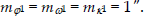
Orbit determination error is mainly resolved by the error of the orbit measurement error and synchronizing the time of orbit determination with the exposure time of the camera on the satellite. The orbital position of the satellite can be acquired by GPS. Processed raw measurement data improves the orbit determination precision to 1m (1σ), that is:

Out of sync timing will lead to linear errors in the direction of flight. If the value of time synchronization precision in the satellite is greater than 0.1ms, then:

Synthesized orbit measurement error and determination error due to out of sync timing: The error (1σ) of GPS raw measurement data used for precise orbit determination is:

The frequency of output data measured by GPS is 1Hz. The position at any time is acquired through interpolation. During the update period of 1s, interpolation error is:

3.3.2 Attitude determination error
The photography attitude error is mainly composed of the attitude measurement error, attitude drift caused by out of sync timing and a change in the relationship between the star sensor and the camera installation due to the spatial thermal environment. The precision of the attitude data output is 1″ (1σ) if we use the gyro and the star sensor to determine the attitude, which is:
The camera must ensure posture stability to give a quality image during imaging. The posture stability of the three-axes is usually superior to 0.001°/s (3σ). Considering that the out of sync timing error is 0.1ms the attitude error caused by this timing error is:
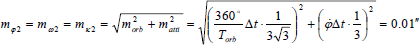
If the camera and the star sensor are integrated, and the installation error of them is about 10″ (3σ), the posture error (1σ) caused by the spatial thermal environment is:

The attitude error (1σ) obtained by these three errors during photography is:

The frequency of data output of the star sensor is 2Hz. The attitude angle at any given time is still acquired by simple linear interpolation. During the update period of 0.5s, the interpolation error is:
3.3.3 Camera pointing error relative to the star sensor
The camera calibration error of the installation angle relative to the star sensor is 2″ (1σ), that is:

3.3.4 Optical system error
The optical system error includes the interior orientation elements error and the optical system aberration. Assuming the orbit altitude is 1000km, the main distance in optical system is 10m, the size of pixel is 10um and pixel resolution on the ground is 1m. The calibration error of the angle between the visual axis and the optical axis of camera is 2″ (1σ), that is:

The calibration precision of the main distance is superior to 1/10000 and the calibration precision of main point is superior to 0.5 pixels, that is:

The calibration aberration precision in optical system is superior to 0.5 pixels, that is: m Δx = m Δy = 0.5 pixels.
3.3.5 Image positioning accuracy
The estimation equation for linear pushbroom CCD image positioning accuracy is:

where Ψ is the sensor angle including the roll angle, the angle between the main optical axis of camera and the z-axis in the body coordinate system and the side view to the left and right of the camera. A desirable value as a preliminary estimate is 0°. y is any point in the image to be determined, it can be made equal to the width of the CCD array.
If we put the error source above into Equation (15) the positioning accuracy is 22.6m (as shown in Table 2). At this point we can conclude that: (1) A super low orbit satellite could increase its image resolution from 1m to below 0.5m, but the position accuracy is only slightly improved (computable image position accuracy is 26.8m when the remote sensing satellite altitude is 645km); (2) Compared with the orbital determination error, the time synchronization accuracy, the geometric calibration and checking precision in orbit, the attitude determination error of the satellite still restricts positioning accuracy.
The values for image positioning precision(1ó)

4. Conclusion
Super low orbit remote sensing satellites maintain lower flight altitudes with ion propulsion to improve image resolution and positioning accuracy.
The use of engineering data in design for achieving image positioning accuracy is discussed in this paper based on the principles of the photogrammetry theory. The exact line-of-sight rebuilding of each detection element and this direction precisely intersecting with the Earth's elliptical when the camera on the satellite is imaging are both ensured by the combined design of key parameters. These parameters include: orbit determination accuracy, attitude determination accuracy, camera exposure time, accurately synchronizing the reception of ephemeris with attitude data, geometric calibration and precise orbit verification.
The image positioning accuracy is 22.6m acquired from simulation calculations of precision. At this point we can conclude that: (1) Super low orbit satellites could increase image resolution from 1m to below 0.5m, but position accuracy is only slight improved (computable image
position accuracy is 26.8m when the remote sensing satellite altitude is 645km); (2) Compared with the orbital determination error, the time synchronization accuracy, the geometric calibration and checking precision in orbit, the attitude determination error of the satellite still restricts positioning accuracy.
Footnotes
5. Acknowledgments
M. Xu acknowledges the supports of the National Natural Science Foundation of China (11172020), and Aerospace Science and Technology Innovation Foundation of China Aerospace Science Corporation.