
Abstract
The main aim of the Xpider project is to analyse, design and develop a low-cost VTOL (Vertical Take Off and Landing) UAV (unmanned aerial vehicle) platform in order to provide a common architectural model for both embedded software and GCS (Ground Control Station) software and communications system. This architectural model should be adaptable to any other hardware platforms or sensors. Some of the key points of the project were, on the one hand, the stabilization process using low-cost sensors and all the associated issues with low quality instruments, on the other hand the interface between the stabilization controller and the navigation controller, not forgetting the secure communication protocols. Additionally, as a side effect of the stabilization process analysis, a new metaheuristic optimization search algorithm has been developed to be used in PID (Proportional Integral Derivative) controllercalibration tuning and has been successfully applied in the stabilization controller.
1. Introduction
When somebody talks about UAVs, people used to think about expensive inertial measurement units, highly accurate sensors and complex embedded software. However, very few people have access to or can afford that technology, and the costs of the hardware and software integration are very high. The Xpider project aims to analyse and design a low cost unmanned platform based on low cost hardware and sensors. With these premises an open adaptable software platform has been designed, which could be used as a basis develop many others projects, possibly using different kinds of hardware platforms and sensors, always with the low cost limitation in mind.
There are many different kinds of UAVs, but taking into account the limitation of the low-cost premise, the Xpider project has focused on short-range, light UAVs with vertical takeoff and landing capabilities. In order to test and apply the achieved design in practice the Open Hardware Arduino platform has been used.
Another important partof a UAV project is the Ground Control Station. The GCS is a key piece in every UAS (Unmanned Aircraft System), as it is the only interface between the autonomous vehicle and the user. The GCS is in charge of monitoring of all the telemetry data and providing a user-friendly display of the data showing usable information for the user or pilot. This information could be status and stabilization information or navigation data. The GCS also needs to be capable of sending commands to the vehicle.
In the Xpider project a complete software architectural model has been developed, including an embedded software model, a GCS software model based in OpenGL widgets and the communication protocol scheme between them. This paper presents the basic functional hierarchy of the software designs, the common challenges to be faced within the context of UAS development and the accomplished solutions.
2. Problem Statement
The Xpider project involves the definition, design and implementation of a close-range UAV software and hardware solution with VTOL capabilities. This objective can be divided into four parts: Embedded Software, GCS software, hardware platform integration and communications interface. Fig. 1 shows the overall design of the project.

System deployment overview.
Regarding the embedded software, the main goal is to obtain a functional hierarchy design able to cope with the common problems due to low-cost and highly heterogeneous hardware. For instance, it will deal with many different kinds of hardware interfaces, low CPU performance (i.e. highly optimized algorithms), and low accuracy sensor readings.
The GCS software model will support different graphical widgets specifically designed to transform the telemetry data intousable information for the pilot, such as avionics Primary Flight Displays, Navigation Displays, Heading Indicators, and raw data panels. It will also display many different command and control interfaces in order to let the pilot use the right command for the current state of the vehicle. With respect to the communications interface, it will be able to manage different message types with different priorities and different grades of reliability. For instance, telemetry data of the gyroscopes sent to the GCS to be monitored does not need to be highly available and can just be broadcast without acknowledgement.
However, some emergency commands sent to the vehicle from the GCS will present high reliability characteristics.
3. Methodology
As the project involves both hardware and software; and due to the need to integrate both, it was necessary to use a prototyping scheme based on the agile or rapid development process. A modified scheme of the spiral model was used in order to define the contents of the four stages in which the project was divided. All of the stages contain specific requirements for the GCS software, the embedded software, the communications interface and the hardware integration.
The four stages defined were named V0 to V3, where V0 consists of the first analysis of the requirements and the identification of the main issues for each stage. This stage is used to analyse and select the hardware and software platform to support the implementation of the rest of the project. After a thorough analysis of the different hardware platforms and software frameworksavailable, the Arduino platform and the Processing Framework were chosen as the hardware platform and the GCS platform. This selectionwasjustified by the dozens of other open source projects based on these platforms; including some of the most recognized UAS open source projects such as ArduPilot [1] or Aeroquad [2].
The second stage, V1, is the first stage with a functional prototype as its aim. The requirements of, and issues to solve in, this V1 stage are: the construction of a first chassis for the vehicle. Thisis based on an X-shaped four propeller model similar to the Mikrocopter platform [3], selection of the electric motors, propeller sizes, electronic speed controllers and the radio module. The V1 version also contains a preliminary module decomposition of the embedded software, the first draft of the communications protocol (supporting basic communication) and the first version of the sensor drivers for reading the physics values of accelerometers and gyroscopes. Regarding the GCS, the V1 project version includes the first 3D model implementation of the vehicle, graphical widget decomposition, a first version of the artificial horizon widget and the implementation of the GCS part of the communications protocol that allows the link between the systems.
The third increment V2 presents the construction of a test bench for the hardware and chassis of the vehicle, an advanced design of the communications protocol (including reliant links) and the design and implementation of the Sensor Fusion and Stabilization Controller (embedded software). Regarding the GCS this increment provides the definition of the hierarchical decomposition of all the graphical widgets, and the integration of a debug and recording framework to be used in calibration and bench tests.
The fourth and finalstage V3 provides the final test hardware platform with all the sensors integrated, an inertial measurement unit consisting of three accelerometers, three gyroscopes, a barometer, sonar and a digital compass. With the embedded software in mind this increment presents the final functional hierarchy and the optimization of the Stabilization, Sensor Fusion algorithms and communications protocol. The final GCS software includes advanced graphical widgets and utilities to support the first flight.
4. Analysis
The main properties of the X configuration chosen for the chassis are well known. The movement of each propeller, consisting of two blades with a certain angle with respect to the horizontal plane (opposite angles between both blades) provides vertical thrust. But as a side effect there are also two horizontal forces (following the movement of each blade), due to the opposite angle of one blade with respect to the other, the horizontal components are cancelled, but inevitably a rotational inertia appears.
A configuration of pairs of propellers with opposites spin directions cancels the different moments of inertia due to each propeller, maintaining the same angular speed.
The basics to let the vehicle acquire a certain pitch, roll and yaw attitude are shown in Fig.2, Fig.3, Fig.4 and Fig.5.

Force decomposition for a pitch turn.
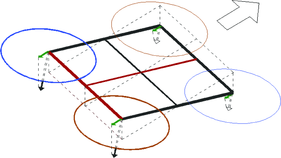
Movement achieved due to pitch gain.
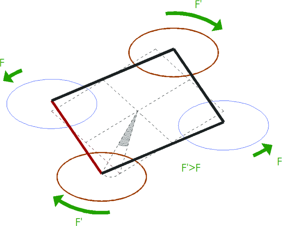
Force decomposition for a yaw turn.
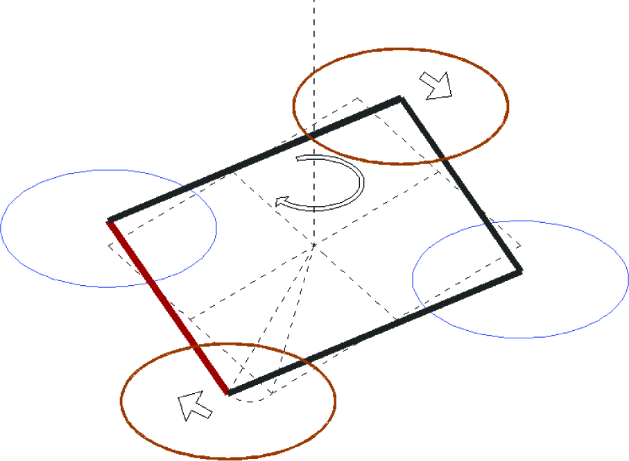
Movement achieved due to yaw gain.
The selection of four propellers facilitates the mobility of the vehicle. It is possible to break the equilibrium of the cancelled forces acting on the vehicle with the angular speed imbalances of the pairs of propellers. This causes changes in the angles that the vehicle makes with the reference frame (in this case the reference frame is defined by the equilibrium state, i.e., there is no movement of the vehicle on any axis), therefore, causing the vehicle to move following a determined vector. The angles referred to are the angles of rotation in three dimensions about the vehicle's centre of mass; commonly known as roll, pitch and yaw. The vehicle's orientation with respect to its centre of mass is known as attitude, and the Stabilization Controller's function is to maintain the vehicle in a certain attitude with respect to these three angles.
5. Architectural Model
5.1 Embedded Software
The architecture of the embedded software follows a well-defined functional hierarchy which outlines the main module and class templates that allow for the software artefacts to be used and extended.
5.1.1 Scheduler
The functional hierarchy of the architectural model for the embedded software will support the basic functionalities of a general purpose UAS. In order to allow as many hardware platforms as possible, and due to the lack of multithreading capabilities in the majority of the low-cost solutions, the first module of the software architectural model is the scheduler. The scheduler will enable the developer to configure and implement different priority pseudo-threads. Each pseudo-thread will be executed at a fixed rate. When many threads are configured with the same rate of execution, a round-robin policy is used. In the case that the processing capacity does not allow the execution of all the configured threads, a deallocation policy is used to select the thread to be executed; the highest priority threads will be the last ones to be deallocated. All the functional modules that compose the system, except for the scheduler, will be an extension of the thread model, i.e. will implement the defined thread interface. The scheduler provides two entry points, an initialization and setup function where the developer can initialize the threads' parameters (perhaps via static initialization or through persistent memory) and call the initialization functions of the other modules to be used such as drivers or communications. The other entry point is the run function that continuously executes the scheduler itself and is called from the main execution thread as having the highest priority (depending on the hardware platform used).
5.1.2 Driver Module
Another important module in the functional hierarchy for a heterogeneous sensor acquisition framework is the driver module. Due to the different sensor acquisition methods, the bus controllers have been defined as low-level drivers. For instance, there is an I2C bus driver, an SPI driver and an analogue-to-digital driver, although other hardware interface drivers can be added. The main idea is to have one high level driver for each sensor (extending the corresponding driver) which hides the hardware interface underneath. In order to define the execution rate of each driver the technical sheet with the acquisition characteristics of the sensor is used.
5.1.3 Sensor Fusion Module
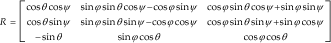
Once the UAS is able to read the data from its sensors the next step is to convert that data into information to be used by the different controllers. The Sensor Fusion Module is responsible for the conversion of the raw data provided by the IMU (Inertial Measurement Unit) into the more suitable attitude parameters: pitch, roll and yaw. There are two main approaches to obtain attitude parameters from linear accelerations and angular velocities. The first one is to use the linear acceleration as the main data and the angular velocities as the correction data in a Kalman Filter [4]. The second method uses the angular velocities as primary data and a Direction Cosine Matrix algorithm [5] to obtain a 3×3 rotation matrix. This rotation matrix breaks the orthogonal principles of the axis and the unit vectors must be re-normalized; the accumulated numerical errors in the rotation matrix are corrected using the linear acceleration values. It was decided to use the DCM algorithm due to its better performance.
The main idea is to maintain an axis matrix which is an estimation of the attitude of the vehicle. This matrix is multiplied by a rotation matrix at a constant rate. The rotation matrix contains the results of the projections of the new reference frame over the original frame of reference (Fig. 6). The relation between the DCM and the Euler angles is shown in Eq. 1, where θ, φ, and Ψ represent pitch, roll and yaw.

Projection over the frame of reference.
Due to the high update rate, the amount of change in each angle is so small that the following assumptions are considered: all cosines values are replaced by one; all the sines are reduced to the angle value in radians; all the sine × sine multiplications are replaced by 0. The assumption of constant angular velocity (Eq. 2) for the whole period is made.

Where ω represents the angular velocity of the gyroscopes.
Starting from the original 3×3 reference frame, the estimation of the resulting attitude can be obtained by multiplying by the rotation matrix:

Where:

Once the result of the rotation is obtained, the resulting matrix is re-normalized and corrected. The acceleration values from the accelerometers are used as correction inputs using a proportional-derivative controller.
The pith, roll and yaw values can be obtained as shown:


The DCM algorithm and all the mathematical principles involved have been studied and developed in Mahony's Papers [6] and [7]. The draft paper by William Premerlani “DCM Imu Theory” [5] has been used as a basis for the Sensor Fusion Module DCM implementation.
5.1.4 Stabilization Controller
The Stabilization controller processes the current state of the vehicle and calculates the power that needs to be provided to the electric motors in order to enable the vehicle to achieve the desired state.
The Stabilization Controller is queried for a specific orientation or attitude, defined by the pitch, roll and yaw angles.
There are many ways to approach the design of the controller. A first approximation is to treat each of the three requested angles as an independent parameter that can be controlled. This way the stabilization problem is divided into three independent problems, each one with an objective parameter controlled through the power settings of each motor.
For all the attitude angles, the error between the requested angle and the current angle is calculated resulting in the input of a PID (Proportional, Integral and Derivative) controller. The difference of power to be supplied between pairs of motors is the output of the PID controller.
As there are three PID controllers, the resulting output is the addition of every controller output. In order to maintain the resulting output within the limits of the capability of the electric motors, another controller merges the attitude controllers' outputs.
Therefore, there are two kinds of inputs for the Stabilization Controller: the current attitude of the vehicle and the vector of desired movement, determined by the three values of the desired attitude.
Due to the low profile of the electronic speed controllers (ESCs), used to transform the digital output into power for the motors, the update rate of the power to the motors is a handicap to be taken into consideration when calibrating the PID controllers.
A PID controller is parameterized by three variables Kp, Ki and Td. There are well known methods to find the appropriate values for these parameters; for instance the Ziegler-Nichols method [8]. Due to the low accuracy of the sensors and the low update rate of the speed controllers it was decided to develop an automatic calibration method. A new metaheuristic optimization search algorithm has been developed to be used in PID calibration tuning. This algorithm is detailed in Section 6.
5.1.5 Automatic and Emergency Behaviour Module
This module defines some of the automatic and emergency behaviours that the vehicle will implement in order to assure the interface with the GCS and the safety of the vehicle.
The vehicle will receive, through an initialization command or even in real time, a flight plan. This flight plan is a sequence of direction vectors to be taken. These vectors define the attitude requested at specific times. If there are no another commands, the vehicle tries to maintain the requested attitude.
The first automatic procedure behaviour is the automatic take off procedure. Once received the secure take off command, the vehicle uses its SONAR and barometer to achieve an automatic take off followed by a stabilization procedure at certain altitude.
The most important of the emergency behaviours is the emergency landing procedure. This procedure is followed if an emergency landing command has been received. It is triggered due to a detected loss of the data link, or because of an achieved special internal status or malfunction. In that case, the vehicle uses its internal SONAR and barometer to descend in a slow, stabilized and safe manner, in order to avoid possible damage due to a crash.
5.2 Ground Control Station Software
The GCS is the only interface between the pilot and the vehicle, so it is very important to have a user-friendly graphical environment for both monitoring the vehicle's state and allowing the pilot to send certain commands to the vehicle.
The framework used to develop the graphical interface is Processing [9]. Processing is an open source programming language and environment initially developed to serve as a software sketchbook for interactive and multimedia applications. It is based on the JAVA programming language and provides easy interaction capabilities with 2D and 3D OpenGL graphics. More importantly, it provides complete integration with the Arduino platform.
The execution model of Processing is very similar to that of the Arduino platform, but the functional hierarchy is slightly different. There is no need for a proprietary scheduler as there is the possibility of using several multithreading and event management libraries, that are very common in graphical environments.
The GCS receives all the data from the vehicle enabling the recording of large data sets in order to know what has happened while running a test or a flight. It also has playback capabilities and as a consequence one of the important modules of the GCS is the Recorder Module. The GCS Software Architecture contains different management widgets that can be monitoring or command widgets. Each management widget has an associated graphical widget that reads and displays the data in the form of useful information.
The graphical widgets hierarchy can be extended, in order to be able to adapt the widgets to specific needs. There are both simple and complex graphical widgets; complex widgets can consist of other simple or complex widgets. The main design issue is to obtain a library of graphical widgets that can be extended and re-used as many times as needed.
The management widgets read the data received through the Comms Module and digest it obtaining usable information to send to the graphical widget. All of the management widgets extend the Recordable Interface. This interface provides the capability of recording and playing back any test session.
The Recorder Module manages the open sessions and provides a way to save all the session data into files in order to let the user playback and analyse all the eventsthat occurred. In the figures (Fig. 7, Fig. 8 and Fig. 9) some widget examples are shown.

Some of the graphical widgets of the Flight Display.
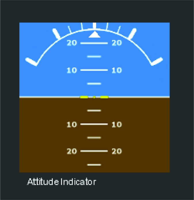
Attitude Indicator graphical widget.

Some graphical widgets of the PID Calibration Display.
5.3 Communications Interface Module
The Communications Interface Module is responsible for the receiving and sending of different messages with different reliability and priority properties.
Due to the possibility of using several physical levels, the Comms Module contains a low level Link submodule that deals with the physical layer and hides the complexity and diversity of the used physical method (radio frequency link, Xbee, WiFi, etcetera). In this case the Xbee radio protocol has been used and the Link submodule implements the Zigbee protocol (only with the high level abstraction layer as the used Xbee chip sorted out most of the protocol).
The Comms Module implements a serial ASCII based protocol which manages four kinds of messages: Reliable, Data, Commands and Heartbeat Messages.
Reliable Messages are messages sent in both directions and having a high importance. These kinds of messages implement an acknowledged and resent policy in order to assure that no message is missed. The handshake protocol starting the link uses these kinds of reliable messages. Some of the critical commands are sent byreliable messages too.
Data Messages are messages sent from the vehicle to the GCS containing telemetry data and low criticality status information. No acknowledged or resent policy is defined for these messages, so some of the messages could be missed.
Command Messages are sent from the GCS to the vehicle. The commands can be divided in two groups, low and high risk. The low risk messages contain commands that, in case of failure, will not jeopardize the safety of the vehicle. High risk commands are critical commands, such as emergency commands, which involve the safety of the vehicle.
Finally, Heartbeat Messages are messages sent in both directions in order to verify the communication link between the vehicle and the station.
6. Hardware Platform
In order to implement and test the proposed design, a hardware platform has been built. The hardware platform has been divided into four prototypes following the previously proposed methodology. Each prototype supports the hardware integration requirement given in each step.
The sensors used in the final prototype are:
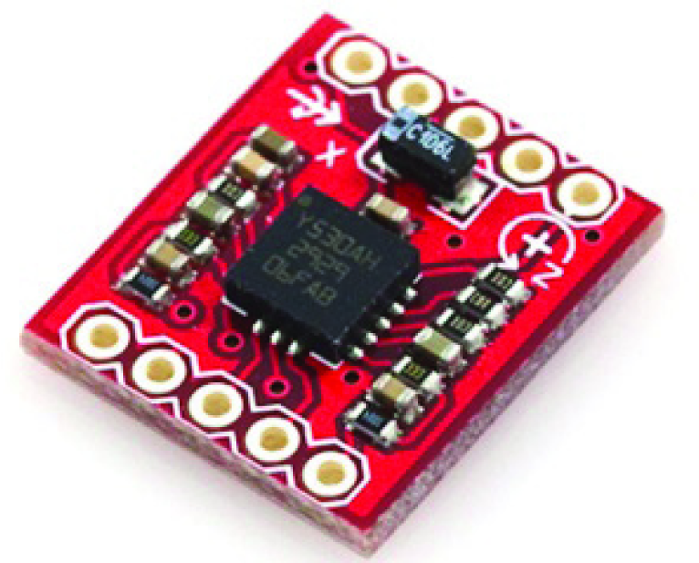
Accelerometers: Triple Axis Analogue Devices ADXL345 with digital input through a I2C interface with SparkFun breakout board (Fig. 10).
Digital Compass: Honeywell HMC6352 with Sparkfun breakout board. Its measurements are used to correct the yaw angle in the Sensor Fusion DCM algorithm, and it is used by the Automatic Behaviour Module in order to maintain a given heading.
Barometer: Mbed SCP1000 barometer with Sparkfun breakout board to be used as an altimeter.
SONAR: MaxBotics LV-MaxSonar EZ1 SONAR. This is used to get accurate measurements of the altitude of the vehicle during takeoff or landing procedures (below 6 meters).

Analogue Device ADXL345 3-axis accelerometer.
LPY530AL dual axis gyroscope.

MaxBotics LV MaxSonar EZ1 SONAR.
The schematics of the main board and the final assembly are shown in Fig. 13 and Fig. 14. The sensors of the IMU are on the left side of the board.
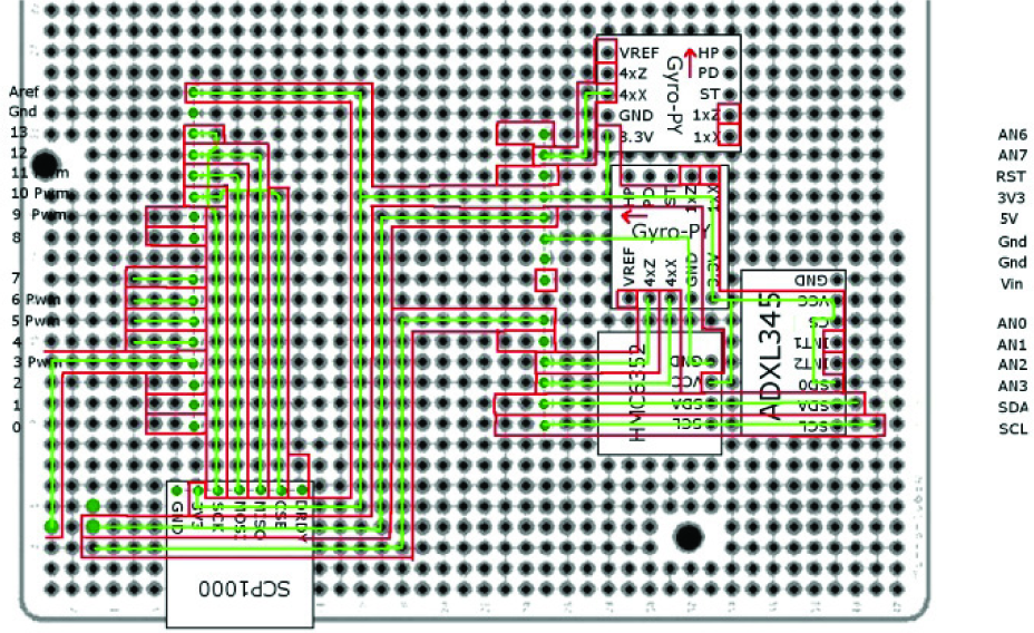
Main Board schematics.

Final assembly of the V3 prototype main board.
Gyroscopes: Two dual axis LPY530AL gyroscopes, one of the axes is redundant. The used Sparkfun breakout board had high pass filters, which were removed in order to prevent noisy delay measurements within the Sensor Fusion Module (Fig. 11).
After a detailed study of the vibration effects on the sensors, a modification of the main chassis was madeto include an impact absorber to minimize the effect of vibration from the motors. The final chassis with the final battery location is shown in Fig. 15.
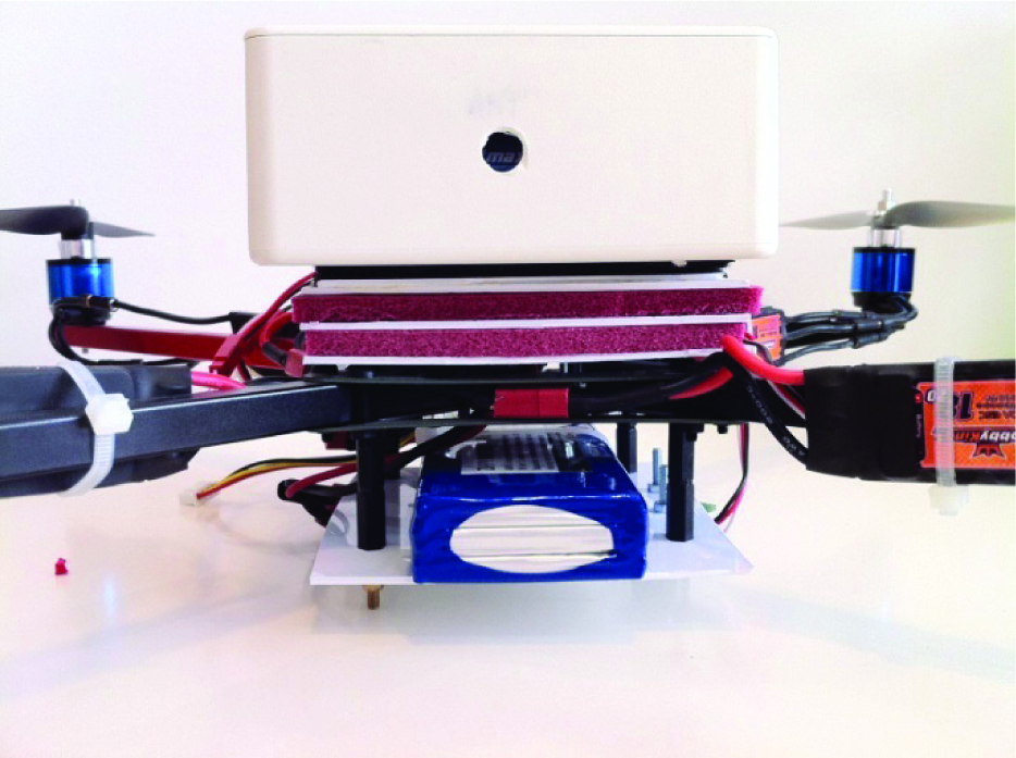
Final chassis assembly with vibration absorber.
7. QSearch
This section presents a new metaheuristic optimized search algorithm designed to be applied in the calibration of PID controllers.
The problem of the calibration of PID controllers can be treated as a search problem, where the Kp, Ti and Td are parameter values to be found. If there is a simulation model of the system there are several methods that can be used to set up the PID controller, but if there is no mathematical model because of the complexity of the model and the characteristics of the measures, then it is necessary to perform a fine calibration by other means.
Hereby, a solution space of three axes is defined by all the possible values of Kp, Td and Ti. In order to test the quality of a selected solution there is the handicap of the high cost of the execution of the fitness function. The fitness function evaluates the quality of a selected solution (Kp, Td and Ti trio). In order to do that, the fitness function consists of the execution of a stabilization routine whilst the vehicle is fixed to a specially designed test bench, and the qualification of the telemetry data reported by the vehicle in order to assign a score to the proposed solution.
A search problem can be approached through many different algorithms, but due to the restrictions on costs and time, it is necessary to find an algorithm which gets a good enough solution with few executions of the fitness function.
The aim is not to find the best solution; it is to find a fair enough solution taking into account a limited number of tests. There are several optimized search methods, commonly called metaheuristics [10]. They select a set of candidate solutions and apply to all of them the same objective function that evaluates their quality. Some of these methods consist of particle filters, genetic algorithms [11][12], the PSO (Particle Swarm Optimization) [13] [14] or the recent Cuckoo Search (CS).
The two main characteristics of an optimized search algorithm are the diversification, or capacity to explore the solution space in an efficient manner and the intensification, or the capacity to take advantage of the principle of locality. That is: in a continuous search space the optimum is always surrounded by points whose quality is very close to the optimum itself.
Particle filters are based on statistical samples. They apply the fitness function to a set of pseudorandom particles, then evaluate the quality of the particles and move or generate a new population of particles following any mathematical law through which, with each iteration, the algorithm converges to the optimum. Genetic algorithms are very similar to particle filters but slightly different in the manner the new samples are taken.
The Cuckoo Search algorithm [15] is a special optimized search algorithm which uses the Lévy Flights [16] as the method to explore and select the random set of solutions to test.
7.1 Lévy Flights
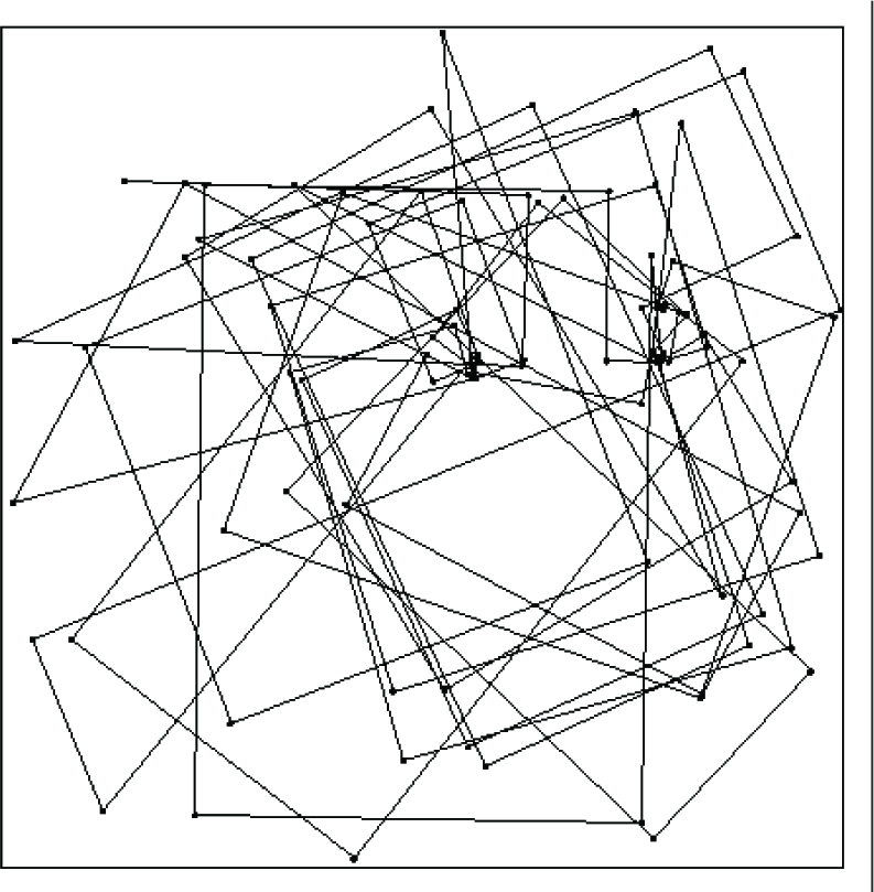
The Lévy Flights theory is very interesting because it offers a very efficient way to explore the solution space. A Lévy Flight is a random walk following a Lévy distribution y = x−a, where 1<a<3. Lévy Flights are Markov processes, very useful when modelling data which tends to group. They are characterized by long distance jumps followed by short distance jumps with abrupt changes of direction.
They are used in the natural world for predators when they cannot find prey with the standard patterns. An example of Lévy Flight can be seen in Fig. 16.

Standard Lévy Flight pattern.
A particle filter that performs a CS uses Lévy Flights to generate the new particle population through the selection of the most suitable candidate particles and maintaining a constant population between iterations.
The main problem of these algorithms is the need of lots of fitness function executions. Besides, the aim of these methods is to find the best solution with the best accuracy, so for the purposes of Xpider project they are not suitable.
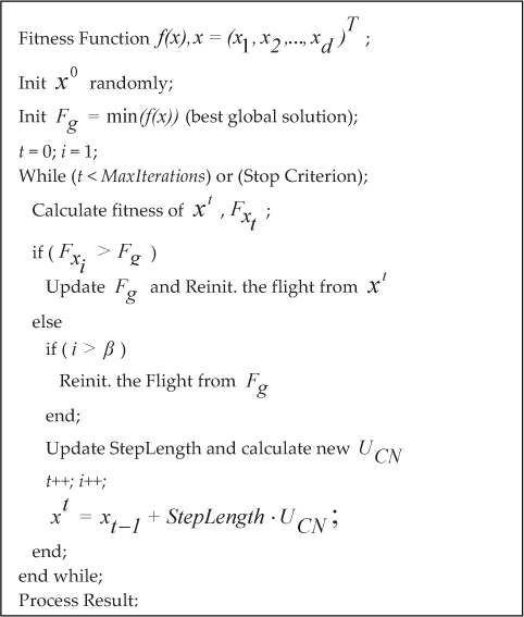
7.2 QSearch Design
A new algorithm was designed in order to suit the Xpider's needs. QSearch is based on a variation of the Lévy Flights, but the distribution followed is y = xa, so it is called Inverted Flight. Moreover, it is not a particle filter, there is only one particle moving following a chain of inverted flights with a limited number of hops. Every new flight starts at the point of the best solution reached. Then, the new flight will search near that position and if it cannot find a better point it will make longer and longer jumps always choosing the perpendicular line with respect to the former hop line and random directions until finding a better solution or reaching the hop limit. The direction of every jump is always normal to the vector which defines the last jump. When a better point is found, the best solution reached is updated and the next flight will start at that point. If the jump limit is reached the flight is ignored and a new flight will begin from the best point kept.
The length of the next jump or step is defined as (Eq. 8):

Where α >0 is a proportional constant related to the solution space dimension and the desired resolution of the solution, δ is between 1 and 3 and it defines the speed of growth of every hop in a specific flight, i indicates the current iteration of the flight, or the hop number in that flight, and it will be reset to 1 when a new flight begins.
In order to calculate the direction of the next jump, a unit vector UCN is calculated, defined by the two points C (Current) and N (New). In order to do that, the OC vector, which defines the last jump taken, defined by the points O (Old) and C (Current), is used. UCN is perpendicular to OC, so a random (R)point in the solution space is chosen to build the vector CR (from C to R). Now the cross product OC × CR is used to build the vector CN which is normal to the plane containing OC and CR, so that CN, is perpendicular to OC. Once the CN is obtained it is transformed by the desired unit vector UCN. The next location of the jump destination is defined as (Eq. 9):

For the first jump, as there is no O (Old), a new vector CN is chosen randomly. Once obtaining a new UCN vector the key points are updated: C will be O, N will be C, and the interaction begins again.
Once the new jump is done, the destination point N (New) is tested with the fitness function. If the score of N is better than the best score found, a new flight is started from that point, if not a new iteration in the flight is done. The pseudo code for the algorithm is shown below:
Pseudocode for QSearch Algorithm.
Where β is the limit of jumps in a flight and is defined in order to optimize the solution space exploration. β should be between 6 and 8, δ between 1 and 3, and α depends on the solution space properties and dimensions.
7.3 QSearch Results
In order to evaluate the performance of the QSearch algorithm two kinds of tests have been used. On the one hand a well-known test function has been selected (Michaelwicz Function), and on the other hand a fitness function has been developed in order to apply the QSearch on the PID Stabilization Module calibration.
The Michaelwicz function (Fig. 17 and Eq. 10) contains many local maximums and minimums and it has its global minimum at the point (2.2031,1.5704) with a value of (−1.8013).

Michaelwicz test function.

In Fig. 18 a QSearch execution over Michaelwicz function is shown with a 3-6-3 (α-β-δ) settings and 100 iterations (fitness function runs) with a result of (−1.7836) at point (2.2354,1.5736).
Test 3-6-3 and 100 iters. (2.2354,1.5736)=−1.7836
More than 100 iterations does not allow better results, but if the α parameter is reduced the average result is more accurate as is shown in Fig. 19 (2-7-3 settings and 100 iterations).

Test 2-7-3 and 100 iters. (2.2079,1.5649)=−1.7995
In Fig. 20 the results are much better when reducing the α parameter and increasing the iterations to 240, obtaining an average result of (−1.80128) at the point (2.2017,1.5706).

Test 0.5-8-3 and 240 iters. (2.2017,1.5706)=−1.80128
But a better result (Fig. 21) with respect to the number of iterations is obtained through the (0.5-6-3) settings and 200 iterations, obtaining an average result of (−1.80107) at the point (2.202,1.5731).

Test 0.5-6-3 and 200 iters. (2.2022,1.5731)=−1.80107
As the results were promising, the Qsearch algorithm was tested with the Xpider vehicle on a test bench. The fitness function used (Eq. 11) to evaluate the results was designed taking into account the four different metrics:
Met1: measures the percentage of time in which the vehicle has been within the stabilization limits. To maximize.
Met2: Maximum of the average angle errors with respect to the objective angle for each unstabilized period. To minimize.
Met3: Maximum time lapse between unstabilized periods. To minimize.
Met4: Maximum of the average angle errors with respect to the objective angle for each stabilized period. To minimize.

These metrics were weighted, and the stability limits were configured within a margin of 5 degrees. The solution space was limited as shown in Eq. 12:

Each execution of the fitness function takes 35 seconds with a recovery period of 5 seconds between executions. The fitness function assigns values between −50 and 50. The best manual calibration (through classic methods) resulted in a score of 22.670, while after 40 iterations the best score reached by the Qsearch method was 27.490. In Figs 22 and 23 the first and best iterations are shown.

First iteration in the QSearch PID calibration.

Best score solution reached after only 40 iterations.
8. Conclusion
As a result of the Xpider project a complete architectural model for both embedded and GCS software for a VTOL UAV low cost platform has been accomplished. Moreover, this architectural model with a well-defined functional hierarchy has been successfully tested on a UAV platform based on Arduino and Processing environments.
As an additional contribution from this work, as part of the optimization of the calibration of the PIDs, a new metaheuristic optimized search algorithm has been designed and successfully tested, providing promising results and improving on the PID calibration results found in other ways.
9. Further Research
The next steps in the project will be: to develop the Navigation Module, to extend the GCS functional hierarchy to support new debug features and integration with other existing platforms.
Another important issue will be to build a well-defined communication message dictionary, in order to establish a complete open standard for low cost avionic communications, maybe adapting current communications standards like tactical data exchange LINK16/STANAG5516 and others.
Regarding the QSearch algorithm, more tests will be defined with different test functions, as well as a complete comparison with other current algorithms to evaluate the performance between them. Maybe further development of a particle filter based on QSearch to extend the functionality of the algorithm to other areas of research could be done.