
Abstract
The raised complicatedness of the dynamics of a robot manipulator considering joint elasticity makes conventional model-based control strategies complex and hard to synthesize. This paper presents investigations into the development of hybrid intelligent control schemes for the trajectory tracking and vibration control of a flexible joint manipulator. To study the effectiveness of the controllers, a collocated proportional-derivative (PD)-type Fuzzy Logic Controller (FLC) is first developed for the tip angular position control of a flexible joint manipulator. This is then extended to incorporate a non-collocated Fuzzy Logic Controller, a non-collocated proportional-integral-derivative (PID) and an input-shaping scheme for the vibration reduction of the flexible joint system. The positive zero-vibration-derivative-derivative (ZVDD) shaper is designed based on the properties of the system. The implementation results of the response of the flexible joint manipulator with the controllers are presented in time and frequency domains. The performances of the hybrid control schemes are examined in terms of input tracking capability, level of vibration reduction and time response specifications. Finally, a comparative assessment of the control techniques is presented and discussed.
1. Introduction
Currently, elastic joint manipulators have received a great deal of attention due to their light weight, high manoeuvrability, flexibility, high power efficiency and large number of applications. However, controlling such systems still faces numerous challenges that need to be addressed. The control issue of the flexible joint is to design the controller so that the link of the robot can track a prescribed trajectory precisely with minimum vibration to the link. In order to achieve these objectives, various methods using different techniques have been proposed. Yim [1], Oh and Lee [2] proposed an adaptive output-feedback controller based on a backstepping design. This technique is proposed in order to deal with parametric uncertainty in a flexible joint. The relevant work also being done by Ghorbel et al. [3]. Lin and Yuan [4] and Spong et al. [5] introduced a nonlinear control approach using the feedback linearization technique and the integral manifold technique respectively. A robust control design was reported by Tomei [6] by using simple PD control and Yeon and Park [7] by applying robust H∞ control. An open-loop optimal control approach for generating the optimal trajectory of the elastic robotic arms in point-to-point motion is proposed by Korayem et al. [8]. This method is based on Pontryagin's minimum principle which considers the mobility of the elastic manipulator.
In recent years, tools of computational intelligence - such as artificial neural networks and fuzzy logic controllers - have been credited in various applications as powerful tools capable of providing robust controllers for mathematically ill-defined systems. This has led to recent advances in the area of intelligent control [9, 10]. Various neural network models have been applied in the control of flexible joint manipulators which have led to satisfactory performances [11]. H. Chaoui et al. [12] used a sliding mode control approach that learns the system's dynamics through a feed-forward neural network. A time-delay neuro-fuzzy network was suggested in [13], where a linear observer was used to estimate the joint velocity signals and eliminated the need to measure them explicitly. Subudhi et al. [14] presented a hybrid architecture composed of a neural network to control the slow dynamic subsystem and an H∞ to control the fast subsystem. A feedback linearization technique using a Takagi-Sugeno neuro-fuzzy engine was adopted in [15]. Lin and Chen [16] propose a combined rigid model-based the computed torque and fuzzy control of flexible-joint manipulators.
As to another aspect, an acceptable system performance with reduced vibration that accounts for system changes can be achieved by developing a hybrid control scheme that caters for the rigid body motion and vibration of the system independently. This can be realized by utilizing control strategies consisting of either non-collocated with collocated feedback controllers or feed-forward with feedback controllers. In each case, the former can be used for vibration suppression and the latter for the input tracking of a flexible manipulator. A hybrid collocated and non-collocated controller has been widely proposed for the control of flexible structures [17, 18, 19]. The works have shown that the control structure gives a satisfactory system response with significant vibration reduction as compared to a response with a collocated controller. A feedback control with a feed-forward control for regulating the position of a flexible structure has been proposed previously [20, 21]. A control law partitioning scheme which uses the end-point sensing device has also been reported [22]. The scheme uses an end-point position signal in an outer loop controller to control the flexible modes, whereas the inner loop controls the rigid body motion independently of the flexible dynamics of the manipulator. However, to the best of our knowledge, there is still no research which adopts intelligent schemes - especially the fuzzy logic approach - for both collocated and non-collocated feedback schemes. Moreover, there is still no article focusing on a comparison study between the non-collocated control and feed-forward control of an elastic joint manipulator.
This paper presents an investigation into the development of hybrid intelligent control schemes for the trajectory tracking of the tip angular position and the vibration control of a flexible joint manipulator. Control strategies are investigated based on a collocated PD-type FLC with non-collocated control and a collocated PD-type FLC with a feed-forward scheme. For non-collocated control, a deflection angle is fed back through a fuzzy logic control configuration. In order to evaluate the performance of the non-collocated fuzzy logic scheme, it will be compared with the non-collocated PID scheme. For the feed-forward scheme, an input-shaping strategy is utilized for reducing a deflection effect. The positive zero-vibration-derivative-derivative (ZVDD) shaper is designed based on the properties of the flexible joint manipulator. In this study, we will provide a comparative assessment of the performances of the composite strategies which are evaluated in terms of input tracking capability, level of vibration reduction in the frequency domain and time response specifications. The implementation environment is developed within Simulink and Matlab for the evaluation of the performance of the control schemes. The rest of the paper is structured as follows: Section 2 provides a brief description of the single-link flexible joint manipulator system considered in this study. Section 3 describes the modelling of the system derived using Euler-Lagrange formulation. The composite collocated PD-type FLC with a Fuzzy Logic Control, PID control and input-shaping scheme are described in Section 4. The simulation results and a comparative assessment are presented in Section 5 and the paper is concluded in Section 6.
2. The Flexible Joint Manipulator System
In this study, the joint flexibility of the robot is represented by a linear spring, as shown in Figure 1. The rotary flexible joint module provided by the Quanser system [23] includes a servomotor in the high gear ratio configurations and a free arm attached to two identical springs. The springs are mounted to an aluminium chassis which is driven by the servomotor. Rotating the base of the arm causes the entire arm to oscillate due to the joint flexibility introduced by the springs. An optical encoder attached to the shaft of the DC motor is used to measure the angular position of the shaft 0(t). The joint deflection α(t) is measured by an encoder located at the motor end of the arm.

Rotary flexible joint manipulator
In Figure 2, θ is the tip angular position and α is the deflection angle of the flexible link. The base of the FJM which determines the tip angular position of the FJM is driven by a servomotor. The deflection of the link will be determined by the flexibility of the spring as their intrinsic physical characteristics.
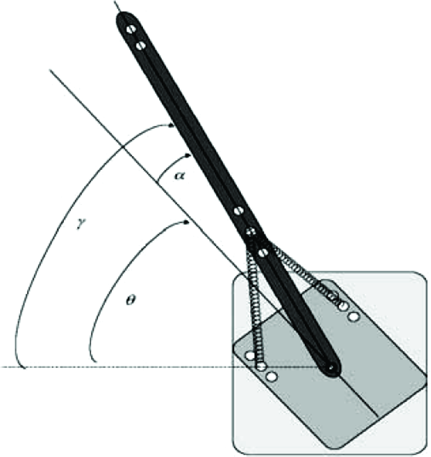
Description of the flexible joint manipulator system
3. The Modelling of the Flexible Joint Manipulator
This section provides a brief description on the modelling of the FJM system as a basis of a simulation environment for the development and assessment of the proposed control techniques. The Euler-Lagrange formulation is considered in characterizing the dynamic behaviour of the system.
The linear model of the uncontrolled system can be represented in a state-space form [23] as shown in equation (1), that is:

where the vector

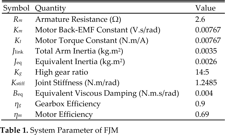
In equation (1), the input u is the input voltage of the servomotor Vm which determines the FJM base movement. In this study, the values of the parameters are defined in Table 1.
System Parameter of FJM
4. Control Algorithm
In this section, control schemes for the rigid body motion control and vibration suppression of a flexible joint manipulator are proposed. Initially, a collocated PD-type FLC controller is designed. Then, a non-collocated fuzzy logic, non-collocated PID and input-shaping schemes are incorporated in the closed-loop system for the control of vibration of the system.
4.1 PD-type fuzzy logic controller (PD-FLC)
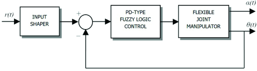
A PD-type FLC utilizing tip angular position error and a derivative of tip angular position error is developed to control the rigid body motion of the system. The hybrid fuzzy control system proposed in this work is shown in Figure 3, where r(t), θ(t) and α(t) are the desired angle, tip angular position and deflection angle of the FJM, whereas k1, k2 and k3 are scaling factors for two inputs and one output of the FLC used with the normalized universe of discourse for the fuzzy membership functions. For a PD-type FLC, triangular membership functions are chosen for the tip angle error, tip angle error rate and input voltage with 50% overlap. Normalized universes of discourse are used for both the tip angle error and its error rate and input voltage. Scaling factors k1 and k2 are chosen in such a way as to convert the two inputs within the universe of discourse and activate the rule base effectively, whereas k3 is selected such that it activates the system to generate the desired output. Initially, all these scaling factors are chosen based on trial and error. To construct a rule base, the tip angle error, tip angle error rate and input voltage are partitioned into five primary fuzzy sets as:

PD-type fuzzy logic control structure
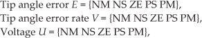
where E, V and U are the universes of discourse for tip angle error, tip angle error rate and input voltage, respectively. The nth rule of the rule base for the FLC, with the angle error and angle error rate as inputs, is given by:

where, Rn, n=1, 2,…Nmax, is the nth fuzzy rule, Ei, Vj and Uk for i, j, k = 1,2,…,5, are the primary fuzzy sets.
A PD-type FLC was designed with 11 rules as a closed loop component of the control strategy for maintaining the angular position of the FJM. The rule base was extracted based on the underdamped system response and is shown in Table 2. The three scaling factors, k1, k2 and k3 were chosen heuristically to achieve a satisfactory set of time domain parameters. These values were recorded as k1 = 0.552, k2 = 0.073 and k3 = −985.
Linguistic Rules of the PD-type Fuzzy Logic Controller

4.2 PD-type fuzzy logic with a non-collocated fuzzy logic controller (PD-FLC-FLC)
A combination of PD-type fuzzy logic and a non-collocated fuzzy logic control scheme for the control of the tip angular position and the vibration suppression of the system - respectively - is presented in this section. The use of a non-collocated control system, where the deflection angle of the flexible joint manipulator is controlled by measuring its angle, can be applied to improve the overall performance as more reliable output measurement is obtained. The control structure comprises two feedback loops: (1) The hub angle as an input to the PD-type FLC for tip angular position control. (2) The deflection angle as an input to a separate non-collocated control law for vibration control. These two loops are then summed together to give a torque input to the system. A block diagram of the composite fuzzy logic control scheme is shown in Figure 4.

PD-type FLC with a non-collocated fuzzy logic control structure
For tip angular position control, the PD-type FLC strategy developed in the previous section is adopted whereas for the vibration control loop, the deflection angle feedback through a non-collocated fuzzy logic control scheme is utilized. In designing the non-collocated fuzzy logic control, basic triangular and trapezoidal forms are chosen for the input and output membership functions. Figure 5 shows the membership functions of the fuzzy logic controller for vibration control. It consists of Negative Big (NB), Negative Small (NS), Zero (Z), Positive Small (PS) and Positive Big (PB), as shown in the diagram. The universes of discourses of the deflection angle, deflection angle rate and input voltage are from 1.2 to −1.2 rad, −0.015 to 0.015 rad/s and −447 to 447 V respectively.

Membership functions of the input and output signals
Table 3 lists the generated linguistic rules for vibration control. The rules are designed based on the condition of the deflection angle and the deflection angle rate, as illustrated in Figure 6. Consider that the joint of the manipulator rotates in an anti-clockwise direction and that the link deflects in a clockwise direction. As illustrated in Figure 6(a), under this condition - and intuitively - the torque should be applied in a clockwise direction in order to compensate the deflection. In this case, the relation between the input voltage and the torque per inertia is shown in equation (3):

Rules generation based on the motion condition

Linguistic rules for non-collocated fuzzy logic control

Meanwhile, if the joint rotates in a clockwise direction, as shown in Figure 6(b), and the link deflects in an anti-clockwise direction, the torque should be imposed in an anti-clockwise direction to suppress the deflection motion. In the case where there is no deflection, no torque should be applied. Furthermore, the proposed fuzzy logic control adopts the well-known Mamdani min-max inference and centre of area (COA) methods.
4.3 PD-type fuzzy logic with a non-collocated PID Controller (PD-FLC-PID)
A combination of a PD-type FLC and non-collocated PID control scheme for the control of the rigid body motion and vibration suppression of the system is presented in this section. The control structure of the PD-FLC-PID is not very different from the PD-FLC-FLC and a block diagram of the control scheme is shown in Figure 7.

PD-type FLC with a non-collocated PID control structure
For the rigid body motion control, the PD-type FLC control strategy developed in the previous section is adopted whereas, for the vibration control loop, the deflection angle feedback through a PID control scheme is utilized. The PID controller parameters were tuned using the Signal Constraint blockset of MATLAB via a closed-loop technique. At this moment, the PID controller is optimized by considering the following desired specifications:
Overshoot ≤ 10%
Settling time ≤ 0.75 sec
Rise time ≤ 0.55 sec
The initial parameters for PID controllers must be specified before the Signal Constraint blockset executes the tuning and optimizing process. The initial controller parameters can be obtained either by trial and error or else given as a default by the Signal Constraint blockset. From the results of a Signal Constraint tuning process, the values were recorded as kp = 602.5128, ki = −43.8895 and kd = −19.7696.
4.4 PD-type fuzzy logic with input-shaping (PD-FLC-IS)
A control structure for the control of the rigid body motion and deflection angle reduction of the flexible joint manipulator based on a PD-type FLC and input-shaping scheme is proposed in this section. The positive input-shapers are proposed and designed based on the properties of the system. In this study, the input-shaping control scheme is developed using a Zero-Vibration-Derivative-Derivative (ZVDD) input-shaping technique [21]. Previous experimental studies with a flexible manipulator have shown that significant vibration reduction and robustness is achieved using a ZVDD technique [24]. A block diagram of the PD-type FLC with an input-shaping control technique is shown in Figure 8.
PD-type FLC with an input-shaping control structure
The input-shaping method involves convolving a desired command with a sequence of impulses known as input-shapers. The design objectives are to determine the amplitude and time location of the impulses based on the natural frequencies and damping ratios of the system. The positive input-shapers have been used in most input-shaping schemes. The requirement of positive amplitude for the impulses seeks to avoid the problem of large amplitude impulses. In this case, each individual impulse must be less than one in order to satisfy the unity magnitude constraint. In addition, the robustness of the input-shaper to errors in the natural frequencies of the system can be increased by solving the derivatives of the system vibration equation. This yields a positive ZVDD shaper with a parameter as:
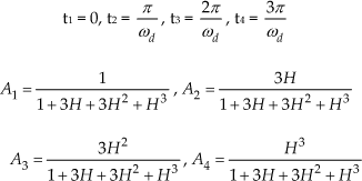
where:

ωn and ζ represent the natural frequency and damping ratio respectively. For the impulses, tj and Aj are the time location and amplitude of impulse j respectively.
5. Implementation and Results
In this section, the proposed control schemes are implemented and tested within the simulation environment of the flexible joint manipulator and the corresponding results are presented. The manipulator is required to follow a trajectory of 50°. System responses - namely the tip angular position and the deflection angle - are observed. To investigate the vibration of the system in the frequency domain, the power spectral density (PSD) of the deflection angle response is obtained. The performances of the control schemes are assessed in terms of vibration suppression, trajectory tracking and time response specifications. Finally, a comparative assessment of the performance of the control schemes is presented and discussed.
Figure 9 shows the responses of the flexible joint manipulator to the reference input trajectory using the PD-FLC in a time-domain and a frequency domain (PSD). These results were considered as the system response under rigid body motion control and will be used to evaluate the performance of the non-collocated fuzzy logic control and input-shaping scheme. The steady-state tip angular trajectory of 50° for the flexible joint manipulator was achieved within the rise and settling times and an overshoot of 0.222 s, 0.565 s and 1.78 % respectively. It is noted that the manipulator reaches the required position within 1 s, with little overshoot. However, a noticeable amount of vibration occurs during the movement of the manipulator. It is noted from the deflection angle response that the vibration of the system settles within 3 s with a maximum residual of ±15°. Moreover, and from the PSD of the deflection angle response, the vibrations at the flexible joint are dominated by the first three vibration modes, which are obtained as 2.94 Hz, 8.83 Hz and 14.52 Hz with a magnitude of 32.38 dB, −12.08 dB and −26.52 dB respectively.

Response of the flexible joint manipulator using PD-FLC
The tip angular position, deflection angle and power spectral density responses of the flexible joint manipulator using PD-FLC-FLC, PD-FLC-PID and PD-FLC-IS are shown in Figure 10. It is noted that the proposed control schemes are capable of reducing the system vibration while maintaining the trajectory tracking performance of the manipulator. A similar tip angular position, deflection angle and power spectral density of the deflection angle responses were observed as compared to the PD-FLC. The steady-state tip angular trajectory of non-collocated fuzzy logic was achieved within the rise and settling times and overshoot of 0.215 s, 0.613 s and 9.68 %, respectively and 0.222 s, 0.501 s, and 9.40 %, respectively for PID control. Meanwhile, with PD-FLC-IS, the manipulator reached the rise, settling times and overshoot of 0.469 s, 0.857 s and 0.16 % respectively. It is notable that the settling time of PD-FLC-FLC is much faster as compared to the case of PD-FLC-PID and PD-FLC-IS. However, the percentage overshoot of PD-FLC-IS is much lower than both cases of PD-FLC with non-collocated control. Besides this, the results also demonstrate a significant amount of deflection angle reduction at the tip angle of the manipulator with the proposed composite controllers. The vibration of the system using PD-FLC-FLC and PD-FLC-PID settle within 1 s, which is much faster as compared to PD-FLC-IS. However, in terms of the maximum residual of the deflection angle, the PD-FLC-IS produces almost a fourfold improvement as compared to the PD-FLC scheme. This result is slightly higher than with both cases of PD-FLC-PID and PD-FLC-FLC, with only a twofold improvement over the PD-FLC scheme. In terms of the power spectral density of the deflection angle response, the magnitudes of vibrations using PD-FLC-FLC, PD-FLC-PID and PD-FLC-IS were reduced to [1.87, −41.95, −48.25] dB, [−2.55, −33.53, −45.55] dB and [17.59, −25.28, −36.69] dB respectively for the first three modes of vibration. It is noted that both the PD-FLC-PID and PD-FLC-FLC schemes produce a higher level of vibration reduction as compared to PD-FLC-IS.

Response of the flexible joint manipulator using composite PD-FLC-FLC, PD-FLC-PID and PD-FLC-IS
Table 4 and Figure 11 summarize the magnitude of the vibration and the level of the vibration reduction of deflection, respectively, for the proposed composite control schemes. It is seen that a high performance in the reduction of the vibration of the system is achieved using both non-collocated fuzzy logic and PID control as compared to feed-forward control based on an input-shaping technique. This is observed and compared to the PD-FLC for the first three modes of vibration. In addition, as demonstrated in the tip angular trajectory response, a slightly faster response with a higher overshoot is obtained using both non-collocated fuzzy logic and PID control scheme as compared to the input-shaping technique. Comparisons of the specifications of the tip angular trajectory responses are summarized in Table 5. In addition, and as demonstrated in the tip angular trajectory response with PD-FLC-FLC and PD-FLC-PID, the minimum phase behaviour of the manipulator is unaffected. In terms of the design complexity, the implementation of the input-shaper technique is much easier as compared to both non-collocated controls as a large amount of design effort is required in order to determine the controller parameters, such as the range of the membership function in the fuzzy logic design and kp, ki and kd gains in the PID design. However, the input-shaper strategy is very sensitive to the system parameter variation and could not compensate for any effect of disturbance as compared to the non-collocated control.
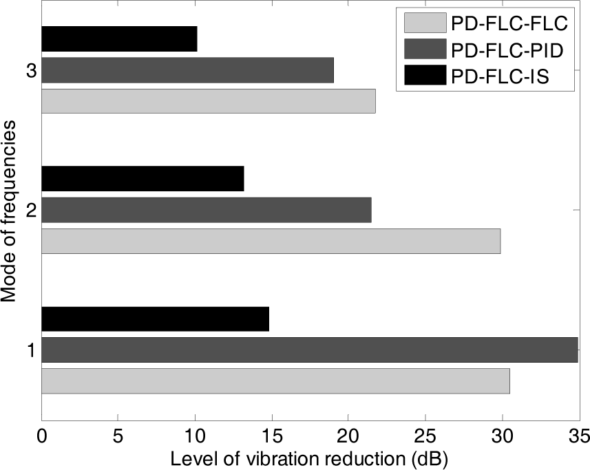
Level of the vibration reduction of the deflection angle
Magnitude of the vibration and level of vibration reduction of the deflection angle

Time response specifications of tip angular position

6. Conclusions
The development of composite fuzzy logic schemes for the trajectory tracking and vibration suppression of a flexible joint manipulator has been presented. The control schemes have been developed based on a PD-type FLC with non-collocated fuzzy logic control, a PD-type FLC with non-collocated PID control and a PD-type FLC with an input-shaping scheme. The proposed composite control schemes have been implemented and tested on a flexible joint manipulator. The performances of the control schemes have been evaluated in terms of input tracking capability and vibration suppression for the resonance modes of the manipulator. An acceptable performance in input tracking and vibration control has been achieved with the proposed control strategies. A comparative assessment of the control schemes has shown that the PD-FLC with non-collocated strategies performs better than the PD-FLC with a feed-forward technique in respect of the deflection angle reduction of the elastic joint. Moreover, in terms of the speed of responses, PD-FLC with non-collocated PID and FLC results in a faster settling time response with high overshoot as compared to PD-FLC with a feed-forward scheme. The work thus developed and reported in this paper forms the basis of the design and development of composite control schemes for the input tracking and vibration suppression of multi-degree of freedom robotic arms with flexible links and joints.
Footnotes
7. Acknowledgments
This work was supported by the Faculty of Electrical & Electronics Engineering, University of Malaysia Pahang, and especially the Control & Instrumentation (COINS) Research Group.