
Abstract
In this paper, we discuss GNSS (Global Navigation Satellite System) guidance for field mobile robots. Several GNSS systems and receivers, as well as multiple measurement methods and principles of GNSS systems are examined. We focus mainly on sources of errors and investigate diverse approaches for precise measuring and effective use of GNSS systems for real-time robot localization. The main body of the article compares two GNSS receivers and their measurement methods. We design, implement and evaluate several mathematical methods for precise robot localization.
1. Introduction
Precise positioning of a robot is the prerequisite for many tasks in mobile robotics. Without such knowledge, the robot is unable to perform mapping or navigation and thus cannot be considered mobile or an intelligent machine. The set of tasks and methods that lead to the answer to the question “Where am I?” are called localization.
Due to a variety of sensors used in robotics, many diverse localization methods have been proposed. The methods range from simple ones, such as odometry, to fairly mathematically rich ones, such as Markov localization. Generally, we can divide localization methods into two groups:
absolute localization methods;
relative localization methods.
While relative methods are referenced to surrounding objects and mostly express displacement between two robot positions, absolute global methods use a global reference frame, which defines a global coordinate system.
Localization methods can be regarded as suitable for indoor environments (such as odometry) or suitable for outdoor environments (such as Global Navigation Satellite System – GNSS). Thus, GNSSs are suitable for absolute mobile robot localization in outdoor environments.
The best known GNSS uses a GPS (Global Positioning System) to calculate the position of the robot. However, this may result in several errors, as there are many different factors that affect the GPS signal. To improve the precision and accuracy of GPS positioning, many researchers use filters such as the Kalman filter [1,5,6,13].
Further improvements of mobile robot localization using GPS could be achieved by adding other sensors, resulting in an INS-GPS solution [3] or a sonar GPS-based solution [4]. Other options include using more precise differential GPS [8,9] or real-time kinematics (RTK) GPS [2,6,7].
Such positioning systems are suitable for localization of wheeled mobile robots in outdoor environments, where perturbations due to wheel skidding and slipping need to be addressed [2, 6]. Using more precise GPS systems, such as DGPS or RTK GPS, is well known in agriculture [11]. In other areas of field and service robotics, solutions with standard GPS receivers are used. However, other sensors and mathematically demanding methods may be applied in such solutions. This is sometimes challenging, because mobile robots have only a limited computing capacity and in addition to localization it must perform many other tasks.
This paper presents solutions using the standard GPS receiver, filter-based approaches for improving localization accuracy, and RTK GPS.
The paper is organized as follows. Section 2 describes the basic principles of a GNSS. Section 3 deals with the localization of mobile robots with a standard GPS receiver. We then introduce approaches with mathematical filters for improving robot localization accuracy. Section 4 discusses RTK GPS localization.
2. GNSS framework
GNSSs (Global Navigation Satellite Systems) are satellite systems for measuring position and time on Earth, and are not affected by meteorological conditions. The position can be measured using triangulation and trilateration – intersection point of spherical surfaces, whose radius is equal to the distance between a satellite and a measured position. From a geometrical point of view, three coordinates (latitude, longitude and sea level) can be calculated using three satellites (Fig. 1). However, the fourth satellite is required to measure time. The more satellites are used for position calculation, the more precise the estimate of position should be.

Measurement of the position using three satellites with correct time synchronization.
GNSSs that are currently available are Navstar GPS (GPS) and Glonass. The Galileo system is planned to become available in the near future. The most commonly used system GPS comprises a cosmic, control and a user segments. The user segment includes GPS receivers. These receivers can be used in mobile robotics for robot localization. However, calculating the position using GPS comes with many challenges and the calculation accuracy is affected by many sources of errors:
satellite geometry (the position of the satellites in relation to each other and the receiver); atmospheric effects (delays of signals passing through individual layers of atmosphere); multipath effects (signals bounce off solid objects); relativistic effects; other errors.
Due to the negative impact of these errors of position measurement, multiple hardware and software solutions have been proposed. One of them is to use a more precise measuring unit:
INS-GPS (Inertial Navigation System, positioning precision with up to 1m accuracy);
DGPS (Differential GPS, positioning precision up to 5m [10cm in case of the best implementations]);
WAAS/EGNOS (Wide Area Augmentation System/Euro Geostationary Navigation Overlay Service, positioning precision up to 3m);
RTK GPS (Real Time Kinematics, positioning precision up to several centimetres).
Another way to improve the estimate of the position using a GPS receiver is to use some mathematical approaches, such as statistical methods (e.g., Monte Carlo method) or filters (e.g., Kalman filter, moving average filter, etc.). Some of them cannot be used in real-time (Monte Carlo) with mobile robot localization, because they have high computational requirements. Usually, they are used as post-processing methods for data correction.
In our experiments, a standard GPS receiver with estimated positioning precision of about 15 m was used.
The results in Section 3.1 show that while the achieved positioning precision is adequate for vehicle navigation, it is not sufficiently accurate for a mobile robot, where centimetres decide whether the requested task is accomplished. Using the mathematical filters introduced in Section 3.2, the trend of positioning is substantially improved. However, some tasks in mobile robotics require the exact position of the robot, not just the trend of its motion. Therefore, an RTK GPS system was tested (Section 4), with satisfying results. However, the RTK measurements are not available everywhere. That is why the same filters (from Section 3.2) were applied also to the RTK GPS system. Finally, an algorithm for high precision GNSS guidance for a field mobile robot was proposed.
3. Localization of mobile robot with a standard GPS receiver
For the localization of a mobile robot with a standard GPS receiver a cheap I-Tec Bluetooth GPS receiver model BT-308 was used (Fig. 2). This device uses an encoded way of measuring (standard NMEA-0183 at 57 600 b/s) and works with a recording period from 0.1 sec. Measurements of a position were carried out by the absolute position estimation method in an area smaller than several square kilometres. Therefore, all measurements were equally affected by global errors. EvEgps software developed for data acquisition from the GPS device with standard NMEA 0183 was used.

I-Tec Bluetooth GPS receiver.
3.1 Measurements
The stationary point measurement (Fig. 3) estimates the localization of the robot before the start of its activities and it was realized without external antenna. A measurement file contains 90 measurements to ensure stable conditions of the measurement. Fig. 3 shows that this measurement is affected by errors, resulting in multiple positions. These inaccuracies are caused mainly by the interference and obstructed visibility of the sky in urban areas. No existing method can completely diminish these local errors since they were caused by the multipath effect and a small number of visible satellites. This would suggest that a standard GPS receiver is useless for field robot localization in dense urban areas.

Measurement of a stationary point by standard GPS-receiver.
Geometric shape measurement (Fig. 4) considered a circular path-trajectory and was realized without application of external antenna. The measuring data file contained 63 points, which is sufficient to capture the shape of the trajectory. The measurements were conducted in a densely built-up urban area. Comparison of the measured and the real path shows that the measurement errors resulted in systematic displacement (Fig. 4). Errors were caused by an insufficient number of visible satellites (during the entire measurements the average number of visible satellites was equal to 3), the multipath effect and satellite positions. Localization of a mobile robot using a standard GPS receiver is therefore useless. In this type of measurement accuracy is in the tens of metres and is therefore insufficient. The localization of a mobile robot requires higher accuracy than for example the localization of a vehicle. However, such measurements may be used with more precise mathematical filters (see Section 3.2) for capturing the trend of movement of the robot, i.e., at dynamic localization or navigation.

Comparison of real path (blue colour) and measured path (red colour) at geometric shape measurement.
A road with a cusped line shape was measured without application of external antenna. This type of measurement represents the typical trajectory of a field robot. The measured data included 200 points. The number of measured points was bigger, since the total path length was longer. The measurement was realized in a dense built-up area and was affected by global and local errors. In the area situated between high-rise buildings at most four satellites were visible. The visibility became better after leaving this area (white dot in Fig. 5), where the number of visible satellites increased to seven. This fact becomes more evident as the real and measured paths were almost identical. In addition, no multipath effect was noticed, due to fewer reflexive objects. In this case, the measurement was affected by local errors only during a certain period. As mentioned above, local errors cannot be completely eliminated, but using mathematical filters enables determining dynamic localization of the robot successfully (see Section 3.2). The global errors can be considered as a constant. Their elimination requires different methods of measuring (see Section 4).

Comparison of real path (yellow colour) and measured path (red colour) on a road with a cusped line shape.
The final measurement (Fig. 6) considered passing a long road with application of external antenna. 3010 points were measured. In this case the measured path was almost equal to the real one, because the required accuracy was at the level of required accuracy for cars. On average, seven satellites were visible during the measurement. With a very long path and a sufficient number of satellites properly distributed on the sphere, the deviations from the real path were minimal. This proves the primary application of a GPS receiver I-Tec for vehicle navigation.

Measured path of a road (red colour).
3.2 Improving the precision of mobile robot position with signal filtering
The positioning of a mobile robot with a standard GPS receiver can be improved by using specific mathematical filters, such as a Kalman filter or moving average filters.
At the beginning of the 19th century, a German mathematician C.F. Gauss developed a method known as the Least Squares Method (LSM). It allows for estimation of a parameter by minimization of the sum of squares of the differences between individual measurements. GNSSs provide data in fractions of a second. Such a quantity of data cannot be effectively evaluated by LSM, because LSM necessitates processing large matrices. The problem can be solved with recursive filters, which use a part of their outputs as an input for the next calculation. One of them is a Kalman filter, which can process dynamic data with minimal delay, even when fast dynamic changes occur. The result of Kalman filtering is the system state estimated from imprecise measurements caused by some errors. Let a discrete process of subsequent mobile robot positions be described by the state equation:
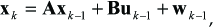
with measurements:

where random variables
An algorithm of Kalman filter is recursive and thus all previous input data are included in the last estimation. Compared to the LSM method there is no need to calculate inversions of large matrices. A discrete Kalman filter (Fig. 7) comprises two basic steps: prediction and correction (sometimes called update or actualization).
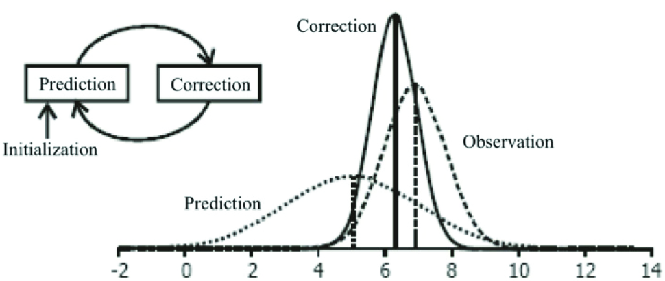
Principle of a discrete Kalman filter.
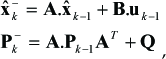
where
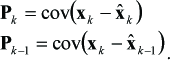

where

On the contrary if covariance matrix
The part(
The described procedure requires an
Moving average is a recursive filter, which smoothes data and simplifies identification of trends. Many types of moving averages exist, but in technical analysis simple and exponential moving average filters are used most frequently.
A simple moving average is established by calculating average values in a specific number of periods (n):
where

Selection of a small calculation period causes moving averages to become more sensitive and generate more signals. A longer calculation period would increase reliability, but the calculated value may achieve non-permissible delay (undesirable within the estimation of the position of a mobile robot).
The described filters were tested on the set of measurements from Section 3.1. From the principles mentioned above, these filters are suitable to estimate the trend of changes in positioning. That is why they were not used for stationary point measurement. After application of filters (Fig. 8) on geometric shape measurement (Fig. 4), similar outputs were obtained. Both filters compensated variable local errors. The shape of the trajectory of the robot is more accurate than that without applying the filters. Global errors caused by the impact of ionosphere, relativistic effects and time synchronization cannot be removed by filtration. Moreover, GPS receiver I-TEC can only make the code measurements on L1 frequency, due to which the measured trajectory remains shifted from the real trajectory.

Geometric shape measurement (blue colour) with an application of:
As for the cusped line shaped measurement, it was affected by local errors only in a certain period. This caused the choppy trajectory at the top of Fig. 9 (blue colour). Local errors can be considered as non-constant and can be removed by applying the filters mentioned above (Fig. 9 – red colour). However, the filtered data by both filters cannot be used for absolute localization of the robot. They can only be used to estimate the relative displacement between two positions of the robot.

Cusped line shape measurement (blue colour) with an application of:
In the case of a road, the application of filters leads to minimal improvements (Fig. 10). These results confirmed the assumptions of previous cases.
Road measurement (blue colour) with an application of:
Generally, the results in this section clearly show that recursive filters diminish errors caused by non-constant local errors (insufficient number of satellites, multipath effect and satellites geometry, etc.). When measurements were influenced by global errors (atmospheric and relativistic effects), the constant character of these errors is evident. To eliminate such global errors, it is necessary to use more precise GPS receivers such as the RTK-GPS Leica receiver introduced in the next section.
4. Localization of mobile robot with an RTK-GPS receiver
For the localization of a mobile robot with an RTK-GPS receiver a Leica GX1230+GNSS/ATX1230+GNSS receiver was used. This receiver is able to receive GPS L1, L2 and L5 frequencies, Glonass L1 and L2 frequencies and Galileo E1, E5a, E5b, E5ab and E6 frequencies. Moreover, this receiver is able to perform code as well as phase measurements with DGPS or RTK corrections. Because of these facts Leica GX1230+ is able to achieve:
0.2 mm positioning precision at phase measurements on L1 and L2 frequencies;
2 cm positioning precision at code measurements on L1 and L2 frequencies.
This receiver has been designed primarily for geodetic measurements, however, its parameters make it suitable for many applications, including absolute mobile robot localization, where centimetres determine whether or not the robot successfully performs its activities.
4.1 Measurements
At first, measurements of a stationary point were performed. Both receivers were verified (Fig. 11). It is evident that the Leica receiver is more accurate in absolute localization, given the possible phase and code measurements on L1 and L2 frequencies. Moreover, Leica also uses Glonass satellites for position estimation. So it has more data available to identify the position. The Leica receiver is able to perform DGPS and RTK corrections, with which the global errors are estimated and compensated. I-Tec GPS receiver performs only code measurements on GPS L1 frequency, which allows the positioning accuracy from 3 to 6 metres. This standard GPS receiver does not use any corrections, so it is affected by both types of errors (global and local).

Stationary point measurement (red colour – I-Tec GPS, blue colour – Leica GPS).
To compare the ability of receivers to evaluate the trend of a robot's movement (i.e., dynamic localization) a round trajectory with varying conditions of visibility of the sky was chosen (Fig. 12). Average speed was approximately 3 km per hour. The data from the standard GPS receiver (I-Tec) show the approximate shape of the real trajectory, but the measurement is affected by constant global error (Fig. 12 red colour). As mentioned in Section 3, such localization is unusable for a mobile robot. In contrast, the Leica GPS receiver has a considerably higher accuracy, even when the RTK corrections are unavailable (Fig. 12 blue colour). These measurements accurately capture the shape of the trajectory and absolute localization can be considered as sufficient. In some places, measurements without RTK corrections were affected by local errors (a smaller number of visible satellites, multipath effect). Therefore, accuracy is lower than in other parts of the measurement (on Fig. 12 right bottom part). Without RTK corrections the measurements with Leica GPS are more prone to local errors. This is noticeable in the area where buildings and trees cover a significant part of the sky. Phase measurements with RTK corrections were not influenced by worsening conditions of the measurement. The measured shape of the trajectory corresponds to the real shape of the robot's trajectory with accuracy of a few centimetres, which is sufficiently accurate for a field robot absolute localization and to successfully perform its activities.

Round track measurement (red colour – I-Tec GPS, green colour – Leica GPS without RTK corrections, blue colour – Leica GPS with RTK corrections).
GPS receivers can also be used to determine the altitude. Such a measurement can be used to detect dangerous states of the field robot (i.e., steep climbing). Every measurement of altitude by GPS is indicated to the surface of the ellipsoid WGS-84 [14]. Such measurements are named ellipsoidal altitude. Real altitude is orthometric – measured relatively in mean sea level. Mean sea level is represented by the surface called geoid. Geoid can be defined as an equipotential surface (i.e., in each point of a geoid there is constant gravity). Geoid has an irregular surface and it is different from any ellipsoid. The problem of conversion from ellipsoid altitude to orthometric altitude is solved by a model of a geoid. The GPS receiver I-Tec uses ellipsoid altitude. Therefore, it is not suitable for altitude measurement. In contrast, the Leica GPS receiver uses orthometric altitude and thus it can be used for detection of dangerous states. In our conditions, the difference between ellipsoid altitude and orthometric altitude should be 20.98 m. The difference between the two altitude measurements varies from 29 to 42.2 m (Fig. 13). Even at altitude measurement the Leica GPS receiver provides higher accuracy. One has to keep in mind that the measurements are affected by global and local errors, as in the previous case.

Altitude measurement by:
4.2 Improvement of absolute localization
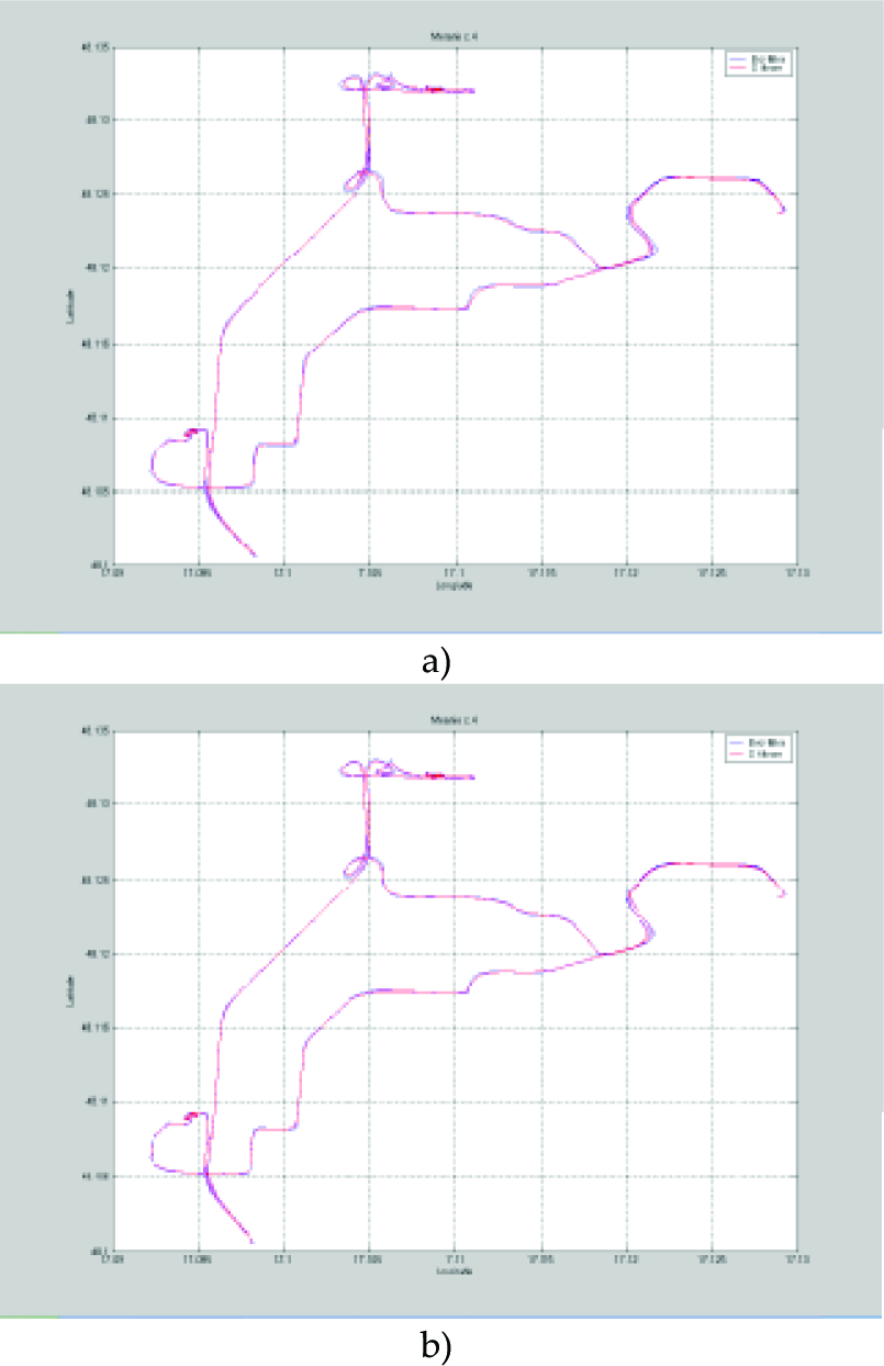
Mathematical filters can also be useful on precise measuring units, e.g., when RTK corrections are not available. Therefore, we tested mathematical filters on data from the Leica GPS without RTK corrections (Fig. 14). Both proposed filters (Kalman and moving average) removed local errors, but global errors remained. Generally, it can be stated that the proposed filters improve the accuracy of dynamic localization, i.e., trend of the robot's movement. With application on the precise GPS receiver without corrections very similar accuracy was obtained as with application with RTK corrections.

Application of mathematical filters on measurement with the Leica GPS without corrections (blue colour – measured data, red colour – Kalman filter, green colour – moving average filter).
5. Conclusion
For mobile robot localization in outdoor environments GNSSs can be used as a powerful tool. However, it is necessary to use additional methods to diminish local and global measurement errors. Local errors can be suppressed by application of specific mathematical filters. However, global errors can be suppressed only by more precise and more expensive devices. Considering application requirements, price-performance analysis will determine a system with sufficient parameters. In general, cheaper devices can only be used to measure changes in the position of the robot, while more expensive devices can be used as a system of absolute localization of the robot at any time.
Footnotes
6. Acknowledgments
This research was supported in part by VEGA 1/0177/11 and VEGA 1/0690/09 grants.