
Abstract
A new visual navigation method for a mobile robot is proposed in this paper. Its originality lies in integrating a sketched map with a semantic map together for the robot's navigation and in using unified tags to help recognize landmarks. In this sketched semantic map, the outline and semantic information of key referenced objects are used to represent themselves and a rough route for the robot's navigation is also sketched. Over the course of robot navigation along the route, and in order to easily recognize the referenced objects from the complex background, a kind of unified label is designed and pasted on the potential referenced objects in advance. A recognition method based on the Pseudo-Zernike Moment and the Normalized Moment of Inertia is used to compute the matching degree between the real-time image of the referenced object and its similar outline in a database. In addition, the odometer information is also fused so as to roughly localize the robot. Finally, through a series of experiments, the advantage and efficiency of the new navigation method with real-time dynamic obstacle avoidance are testified with the help of the imprecise real map and route.
1. Introduction
While robots are gradually moving into a dynamic family environment with personality and diversity, some traditional navigation methods depending on precise maps will become invalid for the complexity of the environment. In this case, to find a simple, direct and interactive means of navigation is imperative.
Since the 1960s, mobile robot navigation has attracted much attention in the community of robotics [1-5]. With the development of computer science and technology, visual navigation has become more popular because of its cheapness, reliability and the abundance of information. DeSouza[4] and Bonin-Font[5] have reviewed the development of this field over the past 10~20 years. For example, Bonin-Font[5] gave a survey of two ways: map-based navigation and mapless navigation. For map-based navigation, he focused on surveying metric navigation and topological navigation. In addition, DeSouza[4] also surveyed the developments of indoor navigation and outdoor navigation in structured and unstructured environments. For indoor structured environments, they focused on surveying geometrical and topological models of space. For indoor unstructured environments, they focused on surveying navigation using optical flows and appearance-based paradigms. Obviously, the sketched map is not mentioned there, let alone the sketched semantic map. However, with the development of human-robot interaction, robots will play an increasing role by interacting with humans according to semantics and other information.
It is noteworthy that Tversk et al. [6,7] set out from the point of view of cognitive science and gave a deep analysis of the role of a sketched map for human navigation. They pointed out the importance of route and direction for navigation, and also emphasized the influence of bias between sketched and physical maps on navigation. Due to the shortcomings of other maps (e.g., grid maps [8,9], topological maps [10], etc.), this kind of navigation by imitating human inquiries for strange routes is very attractive for robot navigation. However, there are only a few studies in this field. We reviewed past works in this field in [11,12]. For example, Kawamura et al. proposed a navigation method based on an Egosphere in [13,14] which did not yet rely on distance information (i.e., range-free). There are some limitations in their work, such as sensing more than two various objects simultaneously, sensing an object in the target description when it is not actually there, being easily confused if duplicates of objects that are in the target region are perceived, and failing in dynamic environments. Chronics and Skubic et al. performed a number of studies on navigation with sonar sensors based on a sketched map [15-17]. There are also certain limitations in their works, such as a high occurrence of mismatch because of the low resolution of the sonar sensors, etc. Of course, in order to overcome these limitations, we also proposed a visual navigation method using a sketched map in dynamic environments in [12]. However, this method needs to take photos for all the landmarks in advance, which will be matched with an image acquired real-time by the onboard camera of the robot. This is a significant limitation, because it is inconvenient for navigating in an unknown environment.
Aiming at the imitating-human-enquiry-navigation method, the key objects in the environment are always described from the point of view of colour, shape, texture and size, etc. By analysis, we find that if we have no physical image for the landmark, it is very difficult to describe it in terms of colour or texture. For the size of the landmark, we only describe it in terms of height and width in a sketched map, so we have no more detailed information. While shape information is more abundant than size information, we can regard it as an effective expression because it can be sketched easily by a mouse or by touch. In all, these key referenced objects in the environment will be described with their corresponding shapes and interrelated semantic information, which is very helpful for robot navigation. Therefore, these supply us with a motivation to study a visual navigation method based on sketched semantic map.
If a robot wants to acquire the outline of a referenced object, firstly, it needs to be sure as to whether that object is in an image acquired by the onboard camera. However, since the indoor environment is very complex, if there is no a priori knowledge, it is hard for a human to figure out the target, let alone a robot do that with computer vision. For a human, in this case, they need some tips or hints to focus on the field of interest in order to shorten the time for searching and improve the rate of recognition. Therefore, a connection needs to be established between the robot and its surrounding environment in order to find the corresponding target in an image as quickly and accurately as possible. This also supplies us with a motivation to design and use unified tags.
In this paper, a visual navigation method based on semantic information, an outline of referenced objects and a sketched route is proposed. In order to make the robot find out whether there is a target in an image as quickly and accurately as possible, we should paste a kind of unified tag for all possible/potential referenced objects. The onboard camera of the robot is used to acquire image information. The onboard sonar sensors are used to make the robot avoid obstacle. The onboard odometer information is integrated with visual information in order to help roughly localize the robot.
2. Representation of the route map
According to the imitating-human-enquiry-navigation mode, the following information is included when the robot navigates: key landmarks (represented by words and outlines, distinct from those which are only represented by an image in [12]), the initial location and direction of the robot, the navigation route and the approximate distance between the starting point and the end point.
For example, a disk is regarded as the referenced object in environment. The word “disk” is used to represent the semantic information. A circle drawn on a sketched map is used to represent the outline of disk, which needs to be matched with the outline of the image acquired in the course of navigation so that the relative position relation between the robot and this disk can be obtained. However, the hand-drawn outline is imprecise and might be distinct from different people. If the hand-drawn outline is used directly for matching with a real image, there might be a serious influence on robot localization. In view of this, we must design an outline database where the outline information of all kinds of referenced objects is included. In the course of matching, we first compare the hand-drawn outline with the outline in the database in order to obtain images with a similar outline. Next, the integrated image features are matched with the real-time image, so that a good matching effect can be obtained for eliminating the uncertainty of the hand-drawn outline.
Suppose the real environment is: Mreal
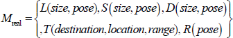
Here L(·) refers to the key landmarks in the environment, S(·) refers to static and motionless objects, which are not regarded as referenced objects because they have no distinct features. However, in the course of navigation, and in considering obstacle avoidance, the robot must deviate from S(·). D(·) refers to certain dynamic objects in the environment over the course of navigation. T(·) refers to the goal and the task area. R(·)refers to the initial pose of the robot.
In this paper, we set out according to the tendency of the hand-drawn route and divide the route into several segments. There is always a key boot point on every segment. The robot runs towards and arrives at the key boot point in every segment. In order to control the robot more conveniently, the motion mode adopts a linear motion between two key boot points in order to avoid the accumulative error from the robot's frequent turning. The selection of a key boot point relies upon the principle of lesser deviation [12]. The key steps are listed as follows:
1) Pick up the candidate of the key boot points. Start from the jumping-off point, detect in turn every discrete point, set the threshold M of angle change and set the minimum and maximum distance threshold Dmin and Dmax. The flowchart is shown in Fig. 1. According to experience, we set M = 20°, Dmin = 1cm, and Dmax = 8cm.

The flowchart for selecting certain candidate points
2) Pick up the key boot points. The key flowchart for picking up the key boot points is shown in Fig. 2. T i represents the i key boot point. T is the number of the candidates for key boot points. ib and ie represent, respectively, the beginning and end detection points. H represents the maximum number of candidates between two key boot points. Libie represents the line segment between the ib candidate and the ie candidate. Max(Dist(p, Libie)) represents the maximum distance among all discrete points p on an original curve between ib and ie to the line Libie. D is the pixel distance between any two neighbouring discrete points. α represents the threshold to decide whether to be a key boot point. Here, H=4 and α = 1.0.

The flowchart for selecting certain key boot points
3. Rough localization
When people search for objects in a complex environment, they always imagine the distinct features at first and then quickly search them. In view of this idea, in this paper the robot searches for objects and recognizes them with a tag in the course of navigation. However, what we want to emphasize is: it is unnecessary to design different tags aiming at different environments and referenced objects, while the tags are unified with a distinct feature that does not indicate any special physical significance but just shows where there is a target in the current field of vision. As for what the target is, there are no signs on the tag. All of the targets need to be recognized later on through the outline recognition arithmetic proposed in this paper. The tag designed in this work may be pasted on any possible\potential referenced objects in environment, which avoids the complexity of designing different tags according to different referenced objects.
Since the outline of the target needs to be figured out by tags, there are certain necessary hypothesizes for the navigation of the environment as follows:
The unified tag needs to be pasted for all possible referenced objects.
It require referenced objects with a single colour, a moderate size and a simple background.
In this environment, the following two steps for the robot in analysing objects according to visual information apply. Firstly, check whether there are any referenced objects in the field of vision of the camera. Secondly, decide whether the referenced object is the target on the sketched map.
3.1 Image segmentation
3.1.1 Recognition of tag
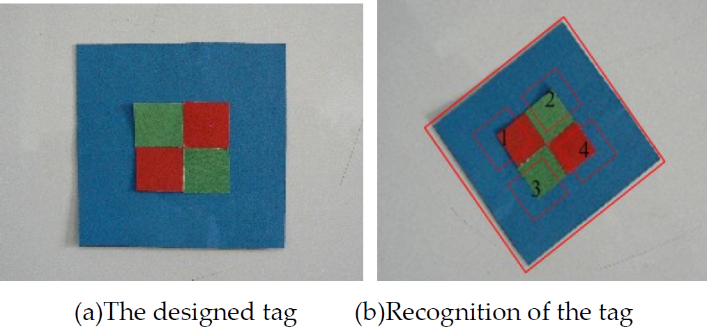
In this work, we design a tag as shown in Fig. 3(a), which can be recognized according to Fig. 3(b).
Label for recognition
At first, search for the blue rectangular frame on the outside -if it exists in the field of vision – and then check for the four small rectangular blocks (i.e., 1,4 red one; 2,3 green one) inside it
For Fig. 3 (b), we analyze and process the colour block in the HIS space. For convenience, the H and, S components are extended to [0, 255]. According to a priori knowledge, each colour block is partitioned according to the following:

This is if we find the blue rectangular frame in an image and then further analyse its interior and if formula (2) or (3) is satisfied and we are sure of the tag in the image.
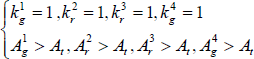

Here, Krx and Arx refer to the number and area of the red area in x small rectangular blocks respectively. Similarly, Kgx and Agx refer to the number and area of the green area in x small rectangular blocks respectively. At refers to the threshold of the area and here we take 15% as much of the area of the small rectangular block according to experience.
The experiment shows that the tag has the ability to reduce the influence of turn and also has good robustness of recognition for more complex and partially occluded environments.
3.1.2 Image segmentation
Here, image segmentation adopts a region growing method, which makes pixels and sub-regions aggregate as a bigger field according to a criterion defined in advance. That is, begin from a set of seeds and add some neighbouring pixels which have similar characters (i.e., greyscale) to every seed in the growing area [18]. In this paper, the flowchart of object segmentation is shown in Fig. 4, where the segmentation result is modified further according to the ratio between the length and width of the circumscribed rectangle.

Flow chart of the object segment
3.2 Recognition of object
Moment technology is a common method for image analysis, representation and outline matching [19]. For example, the Pseudo-Zernike moment has received a great deal of attention for its good orthogonalization, rotational invariance and insensitivity to noise [20]. When computing, move the origin of the coordinate to the barycentre of the object and normalize the image in order to keep the translation and rotation of the Pseudo-Zernike moment invariable[21].
In order to augment the feature information of the image, we also applied a normalized moment of inertia (NMI)[22] to represent the image, which has the same characters – i.e., rotational invariance, translation invariance and scale invariance.
3.3 Feature matching
The 3-order Pseudo-Zernike moment and the NMI have the capacity for resisting the disturbance of the rotation and scale and have a good resolution capability for different objects. Therefore, the Pseudo-Zernike moment and the NMI are used to describe and represent image features. If we match these features with an object, we then need to have a transformation of a hand-drawn outline and obtain its corresponding description matching area.
Here, the 3-order Pseudo-Zernike moment and the NMI are selected as a feature descriptor, which is an 11-dimensional vector V, as in (4):

Here, Aij refers to the Pseudo-Zernike moment with an order n and a multiplicity l.
Based on the above vector descriptor, the procedure for outline matching is as follows: for possible referenced objects, at first, enclose the area by a hand-drawn outline and compute the feature vector of the image from it and its corresponding semantic outline and then compute the Euclidean distance between them respectively. When the distances are less than the threshold, we save their corresponding semantic outlines in a sub-database for recognizing this target later on. Next, compute the mean vector V̄ and the covariance matrix S of all the images in the sub-database, which are regarded as the referenced features of the semantic target. Finally, compute the vector V of the real-time image, i.e., V', and further compute the Mahalanobis distance between V' and V̄ according to the formula (5) in order to recognize the target by comparing the matching result:
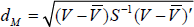
Here, S−1 refers to the inverse matrix of the covariance matrix S.
3.4 Rough localization of the robot
According to the principle of imaging from a pinhole, suppose the mean edge length Lm of a tag shot D
m
away, then the distance Dn between camera and the target is:

When the robot's location relative to the target is worked out according to formula (6), its location in the map can also be estimated.
4. Robot navigation
In this paper, the requirement of the sensors in navigation is: odometer, sonar and onboard camera.
1) Prediction
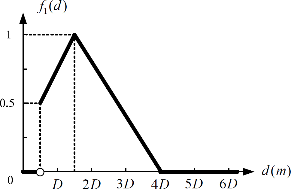
In Fig. 5, two black nodes represent the current key boot points Nc and the next key boot point Nn respectively. Suppose the robot is at Nc, whose direction is NcNn, two grey nodes N0.5 and N0.75 represent the position at 0.5Dist(Nc, Nn) and 0.75Dist(Nc, Nn) on NcNn. The objects O1, O2, O3 and O4 around Nn are within the range of the visual field of the camera. d1, d2 d3 and d4 represent the distances between each object and Nn. α1, α2, α3 and α4 represent the angles shown in Fig. 5. According to experience, if the distance di is too big or too small and the angle αi is too big, it is very difficult to recognize the target. Therefore, we propose two constraint functions, i.e., f1(d) and f2(α) in Fig. 6 and Fig. 7, which is regarded as the basis to judge the referenced object, D refers to the mean shooting distance, α refers to the angle between the referenced object and NcNn, d is the distance between the referenced object and Nn. For each object Oi, the function in (7) is used to evaluate the possibility of the referenced object:
Scheme for the predictive estimation method Constraint function only considering distance factor Constraint function only considering direction warp factor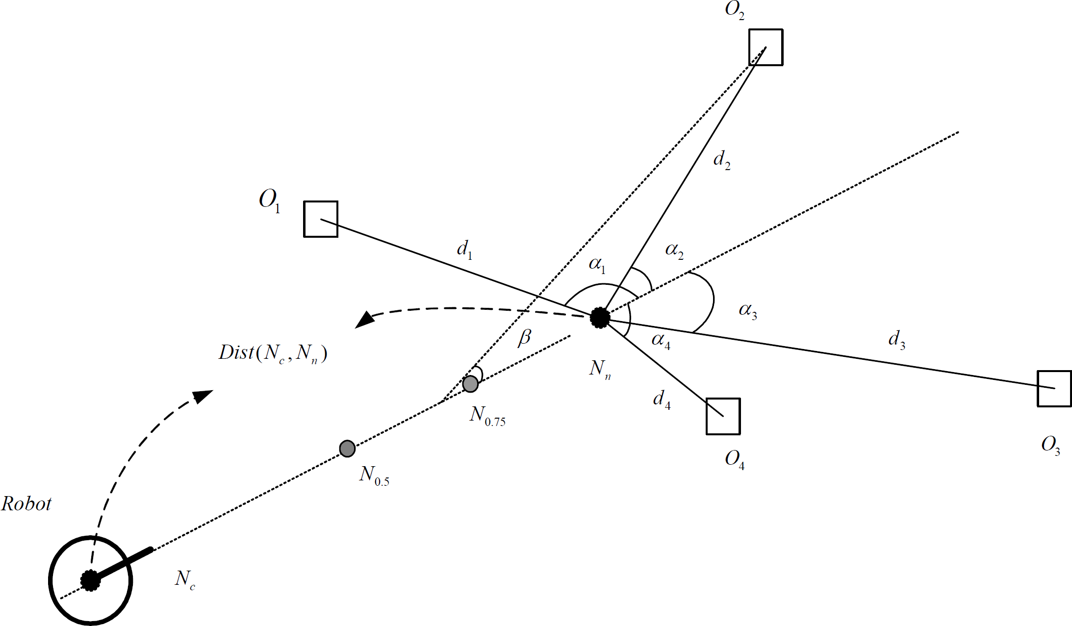


According to the experience, the threshold of maximum possibility is 0.2, i.e., if max{F(i)} < 0.2, then there is no referenced object around Nn. Otherwise, if F(i) is the maximum, then the i th object is regarded as the referenced object. If there is the same F(i) among several objects, then the object with the minimum α will be selected as the referenced object.
2) Scale updating
In the hand-drawn map, the pixel position of each referenced object and the pixel distance between the starting point and the end point are known. According to the scale relation between the real position and the pixel position, we can get the initial scale. The robot may update the scale by comparing the image information with the odometer information.
After updating, if the location of the robot has changed in the hand-drawn map, the scale will be updated. For example, suppose the scale of the map is Roldruler before updating. The position of the current key boot point is L1 and the next key boot point is L2. L2 is replaced by L'2 according to the image information. The scale after updating is Rnewruler according the formula (8):

Here, Ddist(.) refers to the Euclidean distance between two points. RC refers to the updating condition of scale, i.e., here

3) Free navigation
Free navigation means there are no obstacles to avoid in the environment, which may be concluded by the following 3 steps:
Compute the distance between the current key boot point and the next one according to the map scale and decide the running mode to choose.
Turn the camera to search for referenced objects according to the prediction method in this paper.
When the robot arrives to the next key boot point, it localizes itself according to the image and odometer information and then updates the scale of the map and goes to the next segment.
4) Navigation with obstacle avoidance
In order to effectively avoid obstacles over the course of navigation, the flowchart for visual navigation is shown in Fig. 8.
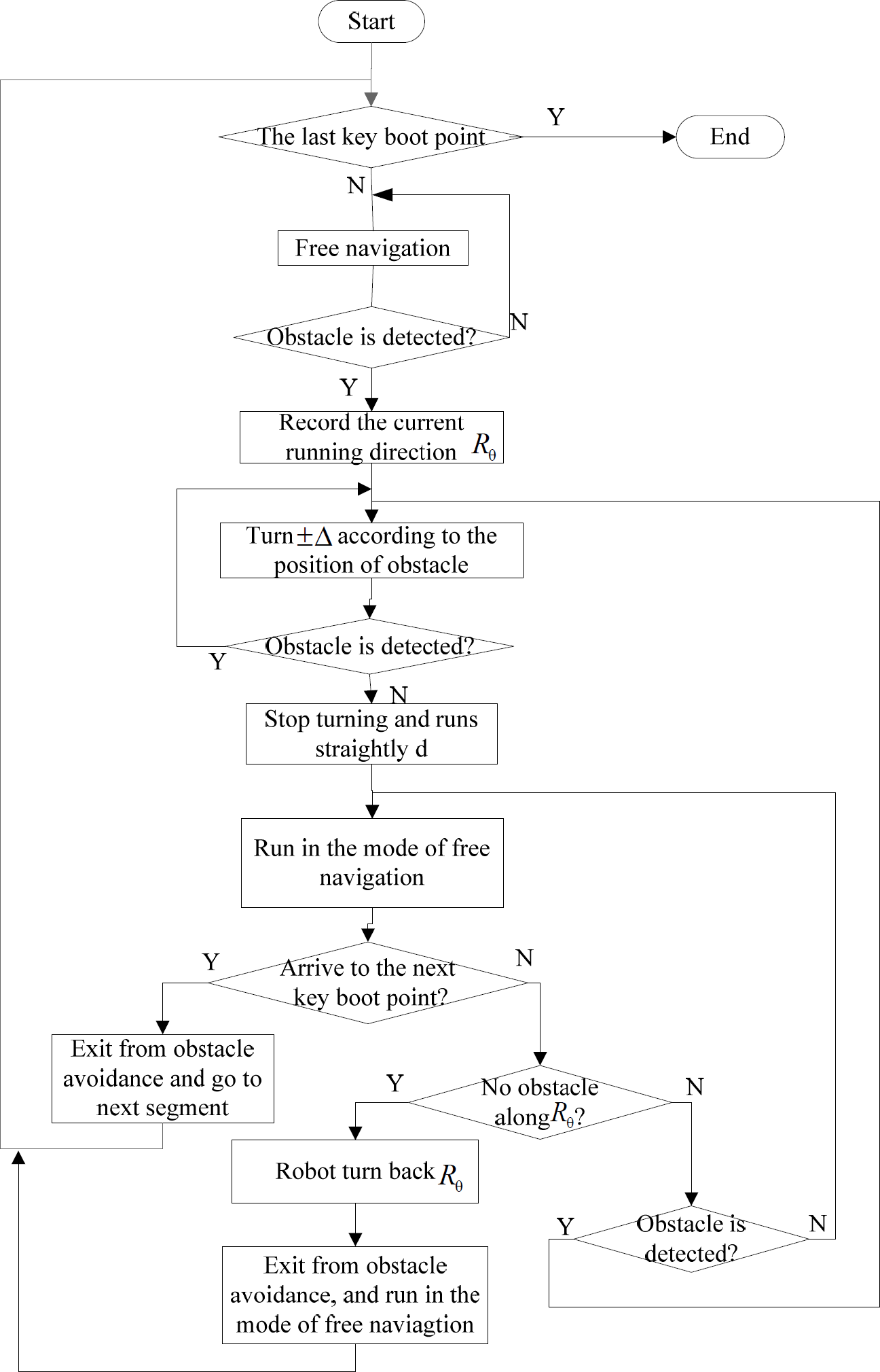
Flowchart for navigation and obstacle avoidance
5. Experimental results
In this paper, a Pioneer 3-DX as the platform of the experiment – in Fig. 9 – is assembled with an embedded controller, motors with 500-tick encoders, 19cm wheels, a tough aluminium body, 8 forward-facing ultrasonic (sonar) sensors, 8 optional rear-facing sonar, 1 laser rangefinder (not used here), 1 indoor PTZ camera system (Pan range: −100° – +100°, Tilt range: −30° – +90° (vertical), camera video signal output: NTSC analogue, colour, 480×350, Lens: 42°×31° field of view, 3.5mm-91mm focal length) [23]. In order to testify the navigation arithmetic, we conduct the experiment in a robot laboratory (seen also in Fig. 10) from 5 points of view, where some referenced objects – i.e., “washbasin”, “Pillow” and “dinner plate” – are selected.

Pioneer 3-DX robot
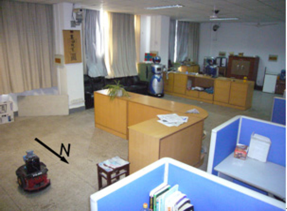
Real experiment environment
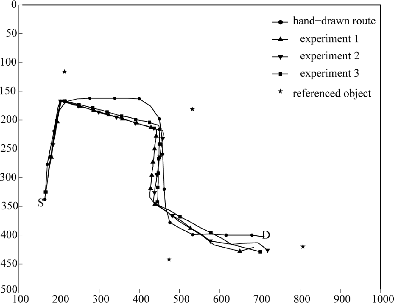
Experiment 1: In the event that other information remains invariable, only change the turning direction of the tag on referenced objects. The tag pasted is clockwise rotated 0o, 20o, 45o respectively. S and, D represent the initial and goal positions of robot. The experimental results of three experiments are shown in Fig. 11.

Influence of the change of label rotation
Analysis of the experimental results: when the tag is pasted arbitrarily, the robot always detects the tag and recognizes the target by image segmentation so that the robot can navigate successfully.
Influence of the change of label position
Analysis of experimental results: when the tag is pasted in different position on referenced objects, the robot always detects the tag and recognizes the target by image segmentation, so that the robot can navigate successfully. However, if a tag is pasted on the margin of a referenced object, this might have an effect on image segmentation and even on navigation. In this case, we should try to avoid it.

Influence of the distance change
Analysis of experimental results: seen from Fig. 13, generally speaking, when the approximate distance is close to the real one, the scale can be accurately updated according to the image information so that the robot will navigate successfully. However, when there is a large difference between them, the robot will be lost in the navigation.

Influence of the sketched outline change
Analysis of the experimental results: when the hand-drawn outline changes, the robot can still recognize the referenced objects and navigate successfully. This is because these features of referenced objects are not fully represented by a real-time hand-drawn outline but represented by the integrated outline features according to the corresponding outline database. Therefore, the sketched outline is not certain to be precise.

Results for outline database changes
Analysis of the experimental results: when the number of referenced objects is changed, the robot can still recognize the referenced objects and navigate successfully. This is because a referenced object is not represented by a single feature but by integrated features from the outline database. Therefore, when the amount is changed a little, there is no great effect on the integrated features or even on navigation itself.

Result for the location change of referenced objects
Analysis of the experimental results: when the relative positions of the referenced object have changed a little, and only if the topological relation among referenced objects remains unchanged, then the robot will navigate successfully. However, if the positions have changed a great deal, or even if some referenced objects go beyond the field of vision of the camera, then the robot will not find the referenced objects. In this case, the navigation might depend on more odometer information.

Results of the same object outline or the occlusion of some objects.
Analysis of experimental result: The recognition based on outline always suffers from the influence of similar /same outline and occlusion. However, known from the experiment, even if there are a few objects which are not recognized rightly, robot will arrive to the next key object with the help of hand-drawn map, because robot can estimate the approximate distance among referenced objects according to the scale updated recently.
The seven experiments all show the same high efficiency and robustness as [12]. However, the method proposed in this paper adapts better to dynamic navigation by comparison with the previous method [12] in Table 1. In Table 1, the recognition ratio of truth refers to Ntr/Nto, Ntr represents the number of true recognition objects, Nto represents the number of total objects; the success ratio of navigation refers to Nsn/Ntt, Nsn represents the successful times of navigation, Ntt represents the total times of navigation. Seen from Table 1, although the recognition ratio of truth for a new method is lower than that for the previous method in a static environment, the new method has a higher recognition ratio of truth than the previous method in a dynamic environment. These recognition results also have an effect on the final navigation, so we find that although the new method in a static environment has a lower success ratio in navigation than the previous method, it has a higher success ratio of navigation than the previous method in a dynamic environment.
The comparison between new proposed method and previous methods

We conclude as follows:
In any case, the path tendency of the robot is almost consistent, which is similar to that of a hand-drawn route. In the course of dynamic obstacle avoidance, the real path fluctuates a little. However, after finishing obstacle avoidance, the robot can resume its original motion tendency with the help of a hand-drawn map.
By changing the position and direction of the tag, the approximate distance between the starting point and the end point, the hand-drawn outline, the number of images in the database and the hand-drawn route, the robot can still navigate successfully. Therefore, the method proposed in this paper is very robust.
Since natural language is applied to robot navigation, it is more flexible, simple and convenient for human-robot interaction. Therefore, the method proposed in this paper is more competitive than that in [12].
Seen from the experimental results, the method proposed in this paper overcomes the limitation of [12] (that is to say, the referenced objects need to have photos taken in advance), so that it is fitter for unknown and dynamic environments.
6. Conclusion
In this paper, a novel visual navigation method based on a sketched semantic map is proposed by an imitating-human-enquiry-navigation method in order to make a mobile robot navigate in a unknown and dynamic indoor environment by interacting with humans. Its originality lies in integrating a sketched map with a semantic map to represent cognitive information for robot navigation. The sketched map includes key landmarks, the initial location and direction of the robot, a hand-drawn navigation route and the approximate distance between the starting point and the end point, which supplies us with some a priori knowledge and assures the navigation tendency and direction. In the semantic map, key landmarks are represented by words with a topological structure, which corresponds to the relative position relations among all the key landmarks. Of course, and in order to make the matching arithmetic more robust, the outline information of key landmarks is also considered as directly matching with database image information and then indirectly matching with real-time image information. During the course of recognition, and since people always imagine some distinct features of objects before searching for them, we design a kind of unified tag, which does not indicate any special physical significance, simply showing where there is a target in the current field of vision. As for what the target is, there are not any signs on the tag. All of the targets need to be recognized later on through the outline recognition arithmetic proposed in this paper. The tag designed in this work may be pasted on any possible\potential referenced objects in the environment, which avoids the complexity of designing different tags according to different referenced objects. Finally, we conduct a number of experiments to testify the high efficiency and robustness of this novel way by changing the position and direction of a tag, the approximate distance between the starting point and the end point, the hand-drawn outline, the number of images in the database and the hand-drawn route, etc. We also compare this novel method with a previous method [12]. In short, although this novel method is a bit weaker than the previous one for navigation in a static environment, it is better for unknown and dynamic environments because of its robust recognition arithmetic and its avoidance of taking photos in advance. It is very simple, flexible, effective, robust and convenient for human-robot interaction through natural language, and it is also very helpful and significant in assisting the harmonious integration of robots with families.
Footnotes
7. Acknowledgments
This work was supported by the National Natural Science Foundation of China (No. 60804063, 61175091), the Natural Science Foundation of Jiangsu Province under grant No. BK2010403, the Public Funds of Image Processing and Intelligent Control Key Laboratory of Chinese Education Ministry under grant No. 200902 and the Science and Technology Innovation Foundation in Southeast University under Grant No. 3208000501. The authors are very grateful to the anonymous reviewers for their valuable remarks which have permitted us to clarify and improve the overall quality of this paper.