
Abstract
The design and control of an active ankle-foot rehabilitation orthotic system that was designed as a wearable and portable rehabilitation and walking assistive tool is presented. This device can measure and assist the six degree of freedoms (DOFs) movement of the human ankle joint by using a Stewart platform mechanism, which can adapt to the displacement of the rotation axis during the movement of a human foot. The estimation method of an instantaneous rotation axis of ankle-foot motion is also proposed. In this paper, the motion measurement and motion control performance of the developed assistive device is evaluated. Static and dynamic motion measurement and motion reproduction performance verification experiments are conducted. The experimental results showed that the developed assistive device is enough for measuring and controlling the human ankle-foot motion.
Keywords
1. Introduction
Strokes are one of the most frequent causes of death in the world. One in six people worldwide will have a stroke in their lifetime. Each year strokes occur in about 15 million people and about six million people die following a stroke [1]. Stroke rehabilitation is a main therapeutic approach which can maximize motor performance and minimize the functional deficits of patient. Rehabilitation and physiotherapy can help to treat the patient's brain and nerves by self-reorganization or plasticity. This is the main therapeutic approach which can maximize motor performance and minimize the functional deficits of patient. In hospital, rehabilitation and physiotherapy are still generally carried out with the assistance of one or more physiotherapists through repeating the exercises many times. In recent years, with the development of robotics technology, many kinds of orthotic and assistive devices have been developed for rehabilitation and power-assist by controlling the position and motion of human joints [2–7]. Although an ankle-foot assistive device is a widely used device which corrects or addresses the motion between ankle and foot, most conventional ankle-foot assistive devices only have one degree of freedom. In the design of an ankle-foot assistive device, the most important thing is to find a way to control the movement of ankle joint naturally and correctly. However, this is difficult since the human has a very complex ankle joint structure. The human foot can not only rotate, but also translate due to the irregular connecting surface between bones. Over the past few decades many researchers have analysed the change of the rotation axis of the ankle joint and many types of optical and mechanical devices have been used [8, 9]. The ankle joint is responsible for the three DOFs rotation motion of the foot, dorsal and plantar flexion, inversion and eversion, internal and external rotation. Even for dorsal and plantar flexion, there are two different axes to respond them with approximately 20 to 30 [degrees] between them. The rotation axis of the foot always changes during the movement. Including the joints of foot, a large number of rotation axes exist in the ankle and foot. Individual measurement of all these axes is very difficult [10], however, most orthotic and assistive devices still fix the rotation axis of the ankle joint using motors or bearings. In order to realize a more effective and comfortable assistant to the foot motion, a device must be able to change its rotation axis during the movement. In this research, to realize such a complex displacement of rotation axis, a novel wearable ankle-foot assistive device, which has a Stewart platform mechanism, is developed. Six potentiometer assembled air cylinders are used to control and measure the posture of the foot in six DOFs (three DOFs rotations and three DOFs displacements of rotation axes), by changing the pneumatic pressures in the cylinders. This device can also estimate the instantaneous rotation axis of the ankle joint, which may be used to realize more validity motion and rehabilitation support. Some experiments have been conducted to estimate and control the subject's foot posture. The results show the validity of the estimate and control performance of the developed assistive device.
2. Wearable Stewart Platform-Type Ankle-Foot Assistive Device
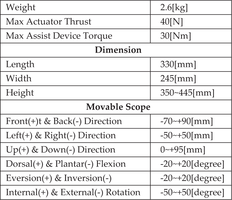
Figure 1 shows the Stewart platform-type ankle-foot assistive device we developed. Six linear actuators are mounted between two plates fixed on the leg and foot (leg plate and foot plate). Two linear actuators are mounted behind the heel (C3, C4) and the other four linear actuators are mounted on both sides of the foot (C1, C2, C5, C6). The motion of the ankle joint is controlled and measured by adjusting the length of the linear actuators [11]. The leg plate part is a ring-like frame that can be opened from the rear for users to enter their. The leg of users is fixed in position using velcro tape. A shin guard is included at the front of the leg plate whose position is adjusted according to the size of the leg of the user. The diameter of the shin guard can be adjusted from 90[mm] to 140[mm]. In addition, to help user easily ware and fix the developed assistive device, we placed an shoe on the foot plate. Shoes ranging from 220 [mm] to 280 [mm] can be mounted on the device. Ball-joints are used to mount six linear actuators between the two plates fixed on the leg plate and the foot plate by. Figure 1(b) shows the developed linear actuator, a potentiometer assembled pneumatic cylinder. The actuator uses the power of compressed air to produce push and pull forces in a reciprocating linear motion. However, there are some disadvantages of pneumatic actuators. A performance at slow speed and at a constant speed of the working bodies' movement is difficult and a requirement of compressed air is the inconvenience of preparation. However, there are more advantages when the device is used with human bodies compared with a conventional electric motor. The advantages are high reliability of work, low cost, ease at reversion movements, explosion and fire safety, ecological purity, accumulation ability, transportation and so on. Even if the developed assistive device malfunctions, the developed assistive device can reduce the risk of accidents because the air can be compressed and expanded. The pneumatic cylinders used are double-acting cylinders and an I-PD controller is applied to control at a desired position by adjusting the air pressure on the two chambers, one for out-stroke and one for in-stroke. An overshoot of an I-PD controller is usually smaller than that of a PID controller. Hence, it is safer to use I-PD controllers in a human assistive device. Table 1 shows the specifications of our assistive device. Figure 2 shows the geometry model of the Stewart platform-type ankle-foot assistive device. The center of the leg plate,


Stewart-platform-type ankle-foot assistive device

Geometry model of the proposed assistive device

Rotation and joints of ankle
Performance of Assistive Device
where
2.1 Controlling of posture (inverse kinematics)
The Calculation and control of the lengths of the cylinders can be posed as an inverse kinematics problem. Provided a desired foot posture

where

where 
By controlling all cylinders to have length
2.2 Measurement of posture (forward kinematics)
Using the measured length of the cylinders 
where 
where 

Using Equation (8), the next search posture 
where
3. Rotation Axis Estimation of Ankle Joint
3.1 Ankle joint
The ankle joint has a very complex structure which is responsible for the up-and-down, side-to-side and medial-to-lateral motion of the foot as shown in Figure 3(a). Despite its name, the ankle joint is not a singular joint but actually a combination of two different joints, the true ankle joint and the subtalar joint, as shown in Figure 3(b). The true ankle joint is made up of three bones: tibia, fibula and talus. This allows for the up-and-down motion of the foot. Under the true ankle joint, there is another joint which is called the subtalar joint. This is responsible for the side-to-side motion of the foot. The motion of the ankle joint is the motion of both these two joints and including the joints in the foot there are about eight axes in the ankle and foot [10]. Only from the posture of the foot, it is difficult analyse the status of all axes. All these axes also displace during the movement due to the irregular shape and contact force of the bones. Several special devices have been developed for obtaining the location of these axes [8, 9].
3.2 Rotation axis estimation
If we assume the foot of the user as a rigid body, then each mount has only one instantaneous rotation axis exits. Using the proposed ankle-foot device, the following method is proposed to estimate the instantaneous axis. According to our method, the rotation axis of the foot plate is a directed line segment and its direction and position are estimated separately.
3.2.1 Direction of rotation axis
For time instance time, t + 1, the foot postures 
where Δt is the time between two measurements. The singular value decomposition of 
where

where
3.2.2 Position of Rotation Axis
Let

By solving this equation with respect to 
where []+ is the pseudo-inverse matrix; 
4. Experiment and Result
Some experiments were conducted to verify the practical effectiveness of the posture measurement and control by the proposed ankle-foot assistive device. The length of cylinders is measured and calculated when a subject moves his/her foot. Using the measured data, the posture of the subject's foot and the instantaneous rotation axis are estimated for each measure point.
4.1 Static and dynamic measurement performance verification experiments
In order to verify the static posture measurement performance of the developed assistive device and confirm the accuracy, the posture of the foot plate is measured manually and the measurement results are compared with the posture estimated results on the proposed method. A device measurement holder is used to measure the posture of the device as ground truth values in accurately (Figure 4). The foot plate is fixed to the upper holder. The leg plate can be adjusted to an arbitrary posture. This posture can be changed by the spacers (Figure 4(b), 4(c)). Figure 4(d) shows an arbitrary posture with plantar flexion. Table 2 shows the measuring error of this developed assistive device. Translation measurement error is less than 0.5 [mm] and rotation measurement error is less than 0.6 [degrees]. In order to verify the dynamic posture measurement performance of the developed assistive device and confirm the accuracy, the motion of the device is measured using a motion capture system and the measurement results are compared with the motion estimated results by the device. Five subjects wore the developed assistive device and rotated their ankles over 15 seconds. (Figure 5) The motions were measured by the developed assistive device and the motion capture system. The maximum error of dorsal/plantar flexion axis is 1.4 [degrees], inversion/ eversion axis is 1.8 [degrees], and internal/external rotation axis is 2.2 [degrees]. These results show that the static and dynamic measurement performance of the developed assistive device is enough to measuring the human ankle-foot motion.

Static measurment performance verification device

Wearing the assistive deviceFigure 1. Stewart
Assist device error

4.2 Motion reproduction performance verification experiments
In order to verify the motion control performance of the developed assistive device, a measured ankle-foot motion was reproduced by controlling the length of cylinders of the device and the reproducibility of the motion is calculated by cross correlation function as a quantification evaluation value. Five subjects wore the assistive device and rotated their ankles randomly over 20 seconds. The motions were measured by the assistive device and then these measured motions were reproduced by the assistive device three times for each subject. In order to evaluate the reproducibility, a cross correlation function was used, which can measure the similarity of two waveforms. For continuous functions 

where Tis time delay,

6-DOF Reproducibility: (a)Left & Right Direction, (b)Front & Back Direction, (c)Up & Down Direction, (d) Dorsal & Plantar Flexion, (e) Eversion & Inversion, (f) Internal & External Rotation
Average reproducibility

4.3 Instantaneous rotation axis estimation experiments
In order to verify the proposed instantaneous rotation axis estimation method, the estimation experiment of test data was conducted. The test data are designed on the assumption that the device rotated the subject's foot down (plantar flexion) around the fix axis [0, 0,-300] in 6 seconds. Figure 7(a) shows the condition of the experiment, which is initial position, final position, the fix rotated axis and center of the foot plate. Figure 7(b) shows the estimated centers of the foot plate and Figure 7(c) shows the instantaneous rotation axes using the proposed estimation method. Though it seems that there is one axis line in Figure 7(c), there are many occasions where the estimated axes lines overlap. The estimated instantaneous rotation axis position and direction error is less than 0.1mm and 0.1 degrees, respectively. Figure 8 shows the estimated posture of the foot plate when the subject wore the device in reality. When the subject wore the device and rotated his/her foot up and down (Figure 8(a)), the displacement of the foot plate was about 72.9 [mm] and the rotation of foot was about 50.3 [degrees]. Figure 8(b) shows the change of instantaneous axis in the movement. The position of rotation axis displacement was movement of about 17.6 [mm] and the direction of it changed by about 13.4 [degrees]. Even though the subject only wanted to move his/her foot up and down, the rotation axis of the human foot still had a very large change. These changes have to be taken into account in the control and support of the human foot motion.
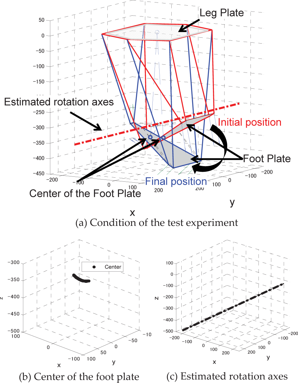
Instantaneous rotation axis estimation simulation

Change of rotation axis
5. Conclusion
In this research a novel wearable ankle-foot assistive device that controls and measures ankle-foot motion was developed. It could be used for rehabilitation and as a walking assistant. In consideration of the displacement of the rotation axis of human foot, a Stewart platform mechanism was used. Six potentiometer assembled cylinders were mounted between the leg and the foot plates. The foot posture of the foot in all 6-DOF direction were controlled and measured in inverse and forward kinematics. The static/dynamic measurement and motion reproduction performance verification experiments were conducted to validate the performance of the developed assistive device. These results suggested the developed ankle-foot assistive device can reproduce a healthy person's walk and physical therapist's motion. In addition, the instantaneous rotation axis of ankle-foot joint was also estimated based on the measured foot posture, which can make the motion control more accurate. In future, we will need to develop a method to create a personal model of ankle-foot joint from the estimated data and, using the model data to control the human motion, gain more accuracy and comfort through which to test the effectiveness in the rehabilitation and walking assistant.