
Abstract
In this paper, we propose a system to detect and track fingertips online and recognize Mandarin Phonetic Symbol (MPS) for user-friendly Chinese input purposes. Using fingertips and cameras to replace pens and touch panels as input devices could reduce the cost and improve the ease-of-use and comfort of computer-human interface. In the proposed framework, particle filters with enhanced appearance models are applied for robust fingertip tracking. Afterwards, MPS combination recognition is performed on the tracked fingertip trajectories using Hidden Markov Models. In the proposed system, the fingertips of the users could be robustly tracked. Also, the challenges of entering, leaving and virtual strokes caused by video-based fingertip input can be overcome. Experimental results have shown the feasibility and effectiveness of the proposed work.
1. Introduction
Because of the logographic nature of Chinese characters, their entry is a very challenging yet important task [1]. In Chinese input systems, Mandarin Phonetic Symbol (MPS) plays a very important role. Mandarin Phonetic Symbols are extracted from Chinese characters. Colloquially, MPS is often referred to as Bopomofo, Zhuyin Fuhao or else abbreviated as Zhuyin. There are a total of thirty seven Mandarin Phonetic Symbols (Fig. 1(a)) and each symbol represents a precise pronunciation. These symbols are building blocks of the pronunciation of the Chinese characters [2]. In mainland China, MPS was replaced by Hanyu Pinyin in 1958. However, in fundamental reference books, such as phrase books and dictionaries, MPS still coexists with Hanyu Pinyin. In Taiwan, MPS remains the prevailing Chinese input method in spite of the drawback of a high character repetition rate for the same MPS combination. Fig. 1 (b) and (c) show the typical layouts of MPS on a computer keyboard and a cell phone keypad, respectively. However, many users have gradually found such design of an MPS layout on keyboards or keypads unsatisfactory, especially for those who are not familiar with input texts on computers. With the prevalence of mobile devices and all-in-one computers, consumers desire a better and easier to use Chinese input interface.

Typical layouts of Mandarin Phonetic Symbols on a computer keyboard and a cell phone keypad.
Mobile computing has become a trend and the relevant technologies are expected to provide unlimited possibilities. As the functionalities of portable devices become more and more sophisticated, the design of the human interface becomes very important. Pen computing (Fig. 2 (a)) emerged due to the urgent need for convenient input interfaces. However, pens could be easily lost and would cause great inconvenience. Therefore, using fingertips to replace pens is favourable for users. Special devices have been investigated to provide a more convenient input interface, such as the pressure sensitive marking menus described in [1]. Also, touch panels that require no pens have become very popular on mobile devices, such as smart phones, in recent years (Fig. 2 (b)). However, touch screens are thicker and heavier compared to normal display devices. Therefore, video-based fingertip input is one possible route for human interface design in small and lightweight portable devices, since even low-tier cell phones are equipped with cameras nowadays, as illustrated in Fig. 2 (c). As for laptop and desktop computers, touch panels are criticized as not conforming to ergonomics under some circumstances. Especially for the emerging all-in-one computers, using touch panels is not a good means for inputting because the users would need to approach the screen, as illustrated in Fig. 2 (d). By incorporating video-based fingertip tracking techniques, the proposed video-based input concept could allow users to control the computer and input data with ease. The concept of the proposed input interface is to allow users to use their fingers to write on any surface, e.g., on a table (Fig. 2 (e)) or even in the air (Fig. 2 (f)). Therefore, video-based human interface is an alternative input method with high potential that provides improved ease-of-use and comfort to mobile device and computer users [3], [4].

Various human interface designs.
OCR/OLCR systems have been under development for many years [5]-[7]. However, their efforts still are built on pen-based input systems. In [5], the researchers tried to allow users to input multiple characters. Unfortunately, this idea is not suitable for hand-held devices because the touch panels on hand-held devices are usually large enough for a single character only. However, the ideas proposed in these works could be accomplished on mobile devices if a camera were used as the capturing device. Using the camera as the input device, users do not need a pen or a touch panel to input characters. Furthermore, they can easily increase the input scope by increasing the distance between the camera and the fingertip. In this paper, we propose a Chinese input system using Mandarin Phonetic Symbols using video-based fingertip tracking techniques. We use fingertips and cameras to replace pens and touch panels as input devices in the proposed system. The framework of the proposed system is illustrated in Fig. 3. First of all, the fingertip needs to be identified from the input video automatically. Afterwards, the located fingertip is tracked and the trajectory of the fingertip is recorded. Then, the recorded trajectory of the fingertip is recognized as Mandarin Phonetic Symbols. Finally, the Chinese Characters can be determined by the input Mandarin Phonetic Symbols and user selection.

The proposed system framework.
For recognizing symbols and characters, Optical Character Recognition (OCR) and Online Character Recognition (OLCR) have both made significant advances over recent decades and achieved very high recognition rates. However, the characters obtained by the proposed video-based fingertip input system have several key differences from traditional OCR or OLCR characters obtained by scanners, touch panels or pen tablets. In traditional OCR/OLCR systems, the trajectories of the fingertip consist of two kinds of stroke: the virtual-stroke and the real-stroke. The real-stroke means those strokes which construct a character or a symbol. By way of contrast, virtual-strokes are those strokes which do not construct a character or a symbol. More specifically, we cannot see the virtual strokes in print characters (which is why we call it virtual). Basically, virtual-strokes are the trajectories between each real-stroke in a character. However, in our application, there are two more types of virtual-strokes, namely entering virtual strokes and leaving virtual strokes. An entering stroke is the stroke before the first real-stroke and a leaving stroke is the stroke after the last real-stroke. In this kind of video-based OCR/OLCR system, we cannot know when the user will start to write down the character or symbol, hence the system simply records the trajectory of the fingertip in all the frames. Since all virtual-strokes are mixed with real-strokes, the challenges to the proposed system are greater than those of traditional OCR and OLCR systems.
The rest of the paper is organized as follows. In Section 2, we explain the fingertip tracking technique designed for the proposed system. Section 3 elaborates the feature extraction module for the tracked fingertip trajectories and the recognition models for Mandarin Phonetic Symbol Recognition. The experimental results are reported and discussed in Section 4. Finally, we draw conclusions in Section 5.
2. Fingertip Detection and Tracking
The fingertip detection process aims to locate the fingertip in the input video automatically. Fingertip detection is performed every N frames. The detected fingertip is tracked using a particle filter for the duration of the N frames.
2.1 Fingertip Detection
The fingertip is detected by adopting the method described in [8]. First, the hand silhouette is extracted using background subtraction [10]. Then, we employ the inner border tracing algorithm [9] to extract the border of the silhouette. These ordered pixels are called border-pixel-vectors (BPVs). We select the middle point P m of line P1P2 as the reference point (see Fig. 4) to calculate the Euclidean distance between Pm and BPV in counter-clockwise order. A distance distribution diagram shown in Fig. 4 can be obtained, and the global maximum corresponds to the location of the fingertip.

(a) Line segment used for generating the reference point Pm from BPV (b) The distance distribution diagram (c) The detected fingertip's location
2.2 Fingertip Tracking
We apply a particle filter to track the target fingertip in this work. Particle filters have the ability to deal with non-linear motions and non-Gaussian noises [11] and, therefore, are suitable for dealing with targets that are close to the camera and exhibiting dramatic motion changes that cannot be easily modelled by Kalman filters. Various designs of particle filters have been applied in different vision-based applications and systems [11]-[15]. Formulating the tracking problems as dynamic systems, the distribution of p(xk | z1:k–1) is obtained via the Chapman–Kolmogorov equation [13] in the prediction stage under the assumption that the pdf p(xk–1 | z1:k–1) at time instance k-1 is known, as shown in Eq. (1). Here, xk denotes the system state at time instance k and z1:k–1 denotes the measurement from time instance 1 to k-1. During the update stage, when the measurement zk at time instance k is available, it can be used to update the required pdf p(xk | z1:k) using Eq. (2). The particle filters aim to approximate the probability distribution of the system state by a sample set xk(i), i = 1… Ns, each associated with a weight wk(i). In the proposed framework, we use an ellipse to model the region of the target fingertip, as shown in Fig. 5. We assume that the ratio of the major axis ak to minor axis bk remains constant at every time instance k. Therefore, we only need to consider the position, scale and rotational angle of the ellipse. Thus, the system state xk at time instance k is defined as xk =[uk vk sk θk] T , where uk and vk are the coordinates of the target fingertip in the image plane, s k is the scaling factor and θk is the rotational angle of the ellipse.

Ellipse fitted on the target fingertip.


where
2.3 Appearance Model of Fingertips
Appearance models are very important to the tracking accuracy of particle-based trackers [16], [17]. Classical colour-based appearance models – such as the works described in [18] and [19] – are not suitable for fingertip tracking since the entire hand has similar skin colours, which would interfere with the tracking process. As shown in Fig. 6, the colour-based particle filter tracker lost track of the target after a few frames. In the proposed system, the appearance model of the particle filter should be able to overcome the problem caused by the inadequacy of colour-based appearance models. Researchers have shown that intensity gradient information could be integrated with colour features for video object tracking [20], [21]. Xu and Li [20] designed a human head tracker that utilized the normalized sum of the gradient magnitude around the boundary of the ellipse model fitted on the human head to complement the interior appearance modelled by colour histograms. Han et al. [21] combined colour histogram bins with gradient orientation histogram bins to obtain more reliable features for tracking. By inspecting the features of the fingertips, it can be observed that the gradient information could capture the shape feature of the fingertip and be useful for compensating for the insufficiency of colour information. Therefore, we integrate the histogram of the oriented gradients (HOG) into the appearance model of the fingertip.

Example of the tracking result of a colour-based tracker.
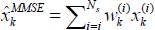
For colour information, a classical colour histogram with Ncolor bins is constructed using the pixels in the ellipse shown in Fig. 7. To integrate HOG into the appearance model, an auxiliary ellipse is associated with each particle, as illustrated in Fig. 7. More specifically, the size of the auxiliary ellipse is the same as that of the original ellipse model of the fingertip and the centre of the auxiliary ellipse is defined as the upper endpoint of the original ellipse model of the fingertip. The magnitude mij and orientation φij of the gradient at each image pixel Iij in the auxiliary ellipse is computed using Eq. (3) and Eq. (4) [22] in order to obtain the HOG. The two dimensional space of mij and φij is divided into NHOG histogram bins [23]. The colour histogram and gradient histogram are concatenated to form the appearance model of the target fingertip. The weight of each particle is computed based on the Bhattacharyya distance [24] D(HistA, HistB) of the appearance of the target fingertip (HistA) and the appearance obtained from the particle (HistB), as shown in Eq. (5). Note that Eq. (5) associates smaller Bhattacharyya distances with larger particle weights via a Gaussian with variance σ. The weights are normalized and the minimum mean square error estimation of the system state is obtained using Eq. (6) [18].

An ellipse for colour histogram construction and an auxiliary ellipse for HOG construction.


3. Feature Extraction and Mandarin Phonetic Symbol Recognition
In this section, we describe the procedures for feature extraction and Mandarin Phonetic Symbol Recognition. The characteristics of Mandarin Phonetic Symbols are very similar to Mandarin characters. More specifically, the Mandarin Phonetic Symbols are mostly constructed by straight lines, except for two symbols  and
and  . Hence, based on the observed characteristics of Mandarin Phonetic Symbols, we design the Inter-Frame Directional (IFD) Code as the features for MPS recognition.
3.1 Inter-Frame Directional Coding
We adopt the vector of fingertips between adjacent frames as the features. Since the stroke directions are slightly slanted due to the different writing habits of different people, we divide the inter-frame stroke direction into eight code words, called Inter-Frame Directional Code, which are described in Fig. 8.

The defined eight inter-frame directional code.
The sequence of a phonetic symbol generates a sequence of directions, which corresponds to a code sequence. For example, the Phonetic Symbol  with stroke order “↙”, “→”, “↙”, “↖” generates the code sequence “5 5 5 5 5 0 0 0 0 0 0 5 5 5 5 5 3 3 3 3” or “5 5 5 5 5 0 0 0 0 0 0 6 6 6 6 6 3 3 3 3”, depending on the writing habit of the person. In the following subsections, we will demonstrate how to utilize the IFD code sequence for effective MPS recognition.
3.2 Entering and leaving stroke elimination procedure
As we mentioned in Section 1, the trajectories of the fingertip will consist of real strokes and virtual strokes. Among these strokes, we further define four types of stroke according to their special characteristics, as follows:
Entering-stroke: the first virtual-stroke
Starting-stroke: the first real-stroke
Ending-stroke: the last real-stroke
Leaving-stroke: the last virtual-stroke
It is noticeable that the entering-stroke and the leaving-stroke are virtual-strokes and the starting-stroke and the ending-stroke are real-strokes. For complete trajectories of the fingertip, the order of these types of stroke is: entering-stroke, starting-stroke, real/virtual stroke, ending-stroke and leaving-stroke. Fig. 9 shows the notation of these strokes to provide a clearer understanding.
Representation of strokes.
As we can observe from Fig. 10, the intermediate virtual stroke is somewhat stable. However, the entering and leaving strokes are very unstable and would severely interfere with the recognition process. To verify this phenomenon, we designed an experiment for recognizing two kinds of trajectories. The first one involves the original trajectories, which contain entering and leaving strokes. The second one involves those trajectories which do not contain entering or leaving strokes. As we can see in Table 2 and Table 4, the recognition rate drops to around 50% when the entering and leaving strokes are included, whether using the HMM or the DTW recognition method. Hence, it is necessary to eliminate the entering and leaving strokes, which are the first and the last strokes in the sequence. In order to classify the first and the last stroke, we must detect the turning points in the video sequence.

Effects of unstable entering and leaving strokes.
The turning points can be obtained by subtracting the current code from the previous code. The difference value dt at frame t is defined as follows:

For example, the difference of the IFD code sequence “5 5 5 5 5 0 0 0 0 0 0 5 5 5 5 5 5 3 3 3 3” is “0 0 0 0 0 3 0 0 0 0 0 −3 0 0 0 0 0 −2 0 0 0”. The meaning of dt depicts how the fingertip changes its direction. When dt is equal to zero, the direction of the fingertip does not change. When dt is positive, the fingertip changes its direction counter clockwise. Conversely, the fingertip changes its direction clockwise when dt is negative. The turning point can be easily obtained by thresholding those non-zero values. In our experiments, the threshold value is 2, which is about 90 degrees. However, through the experiments we find that the code sequence may be “0 0 4 0 0” or “0 0 7 6 0 0”. These are caused by tracking errors, the zigzagging of user input or a slow writing speed. For the first case, we would get two consecutive turning points (there is no turning point perceptually) while for the second case, we cannot get any turning point (there is a turning point perceptually). Hence, we use two criteria for turning point detection. That is, the fingertip's position (ut,vt) is regarded as a turning point if:
Both |dt| and |dt+dt+1| are above the threshold.
|dt+dt-1| is above the threshold.
Fig. 11 shows the detection results using the above criteria. The red circles in Fig. 11 (b) are the detected turning points.

(a) The input trajectory (b) The turning point detection results.
The trajectory between two turning points can be regarded as a stroke. We check these strokes and eliminate those strokes which are too short. The short strokes are usually noise and provide little contribution for recognition. Hence, we discard these short strokes for better recognition results. After obtaining the turning points, we can define the entering and leaving strokes, which correspond to the trajectories before the first turning point and the last turning point. However, from Fig. 10 we can see that sometimes there is no leaving stroke. This is because the users may leave the scene very quickly or the leaving stroke may have the same direction of the ending stroke. In such cases, we should not eliminate the last stroke. Thus, we check the length of the last stroke. If the last stroke is long enough, we treat it as an ending stroke and keep it. Otherwise, we treat it as the leaving stroke and discard it. In Section 4, we will show the experimental results of the Mandarin Phonetic Symbols before and after removing the entering and leaving strokes.
3.3 Recognition Model
The MPS recognition is performed using HMM classification [25]. Graphical models are effective ways to represent and solve problems with uncertainty and complexity [26]. In recent years, the HMM has extensively been applied to speech recognition to resolve segmentation, time warping, stochastic randomness, etc. Prominent results have been widely recognized in the open literature. In terms of the IFD code sequence, we observed that its distortion is quite similar to that of speech recognition because the length of the IFD code sequence varies due to the writing speed.
A Hidden Markov Model is a finite set of states, each of which is associated with a probability distribution. In a particular state, an observation can be generated according to the associated probability distribution. Therefore, given an HMM λ and a sequence of observations O = {O1, O2,…, Ot}, the probability p(O | λ) can be computed, which represents how likely O is to be generated by λ. Each Mandarin Phonetic Symbol s is trained independently to optimize the model parameter λ s by a set of a given observation sequence O. The training process can be achieved by the Baum-Welch algorithm and the likelihood is calculated using the forward algorithm [25].
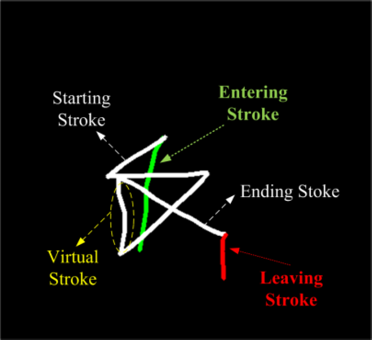
3.4 Confusion Symbol Set
We list the confusion symbol sets of MPS in Table 1. From Table 1, we can observe that the transitions of the IFD code of each symbol in the confusion set look very similar or belong to the subset of the other symbol in the same set. These symbols have higher chances of being misclassified using HMM. Therefore, every symbol that is recognized as one of the symbols in the confusion sets should be further checked by the confusion symbol verification procedure. The confusion symbol verification procedure can verify the correctness of the HMM recognition result according to some predefined rules to resolve the problem of confusing symbols. For example, the main difference between  and
and  lies in first stroke. Since we have successfully extracted the turning points and the strokes, the symbol should be
  instead of
  if the IFD code of the first stroke is 5. Also, there are certain regulations of the possible combinations of the consonant set, the medial set, the vowel set and the tone set in MPS. For example,
  cannot stand alone and must be combined with other symbols. However, it is possible for
  to stand alone. These regulations can also be used for confusion symbol verification.
List of Confusion Symbol Sets

4. Experimental Results
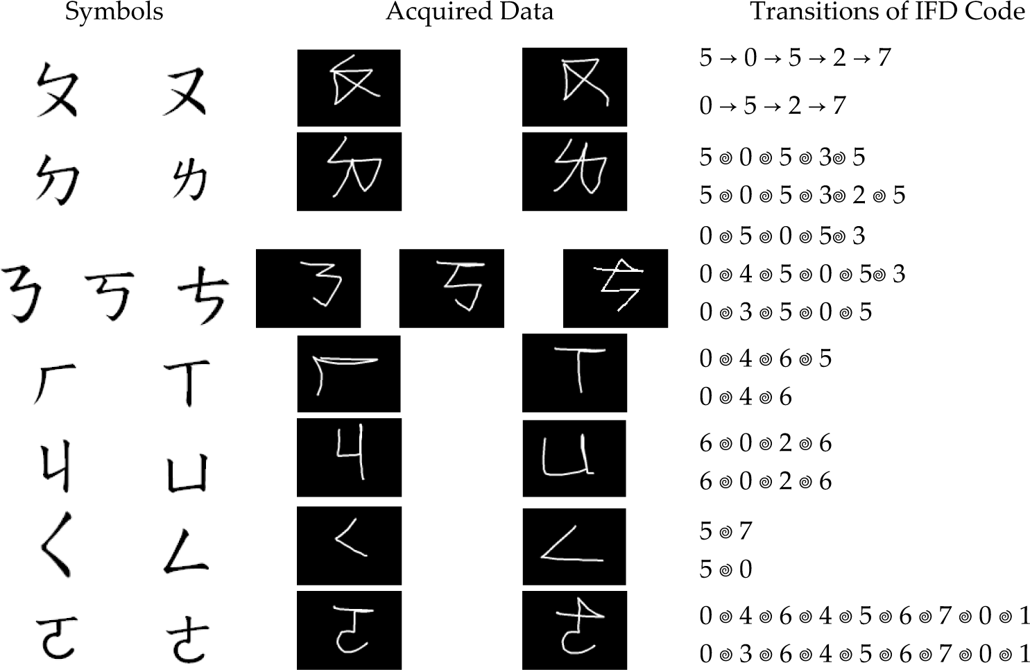
In this section, we demonstrate the experimental results that verify the feasibility and effectiveness of the proposed system. The fingertip tracking results, entering and leaving stroke elimination results and the recognition rates of MPS are displayed in the following subsections. Fig. 12 is an example of the whole system. In Fig. 12 (a), the camera is mounted right above the table. In Fig. 12 (b), the camera is mounted on the top of the monitor so that the user can write the MPS in the air. Fig. 12 (c) and (d) shows the picture captured by the camera where the red circle denotes the tracked fingertip in the current frame and the green circle denotes the location of fingertip in the previous frame. Fig. 12 (e) and (f) shows the tracked trajectories.
Example of the proposed framework. (a) and (b) The capturing environment. (c) and (d) Snapshots from the camera. (e) and (f) The Fingertip tracking results.
4.1 Experimental Results for Fingertip Tracking
For fingertip tracking, the number of histogram bins of the colour histogram Ncolor is set as 512, dividing each of the RGB channels into 8 levels. Moreover, the number of histogram bins of HOG NHOG is set as 64, with 8 levels for the magnitude mij and 8 levels for the orientation φij. Fig. 13 shows the tracking results of the symbol  using the colour histogram-based appearance model. We can observe that the tracker lost track of the target fingertip after a few frames because the colour information cannot discriminate the fingertip from other parts of the hand. The resulting tracking trajectories of such a tracker would lead to inaccurate recognition results. The tracking results of the same symbol using the combined appearance model are shown in Fig. 14. With the auxiliary ellipse and the HOG information, the tracker could accurately track the fingertip. As a result, the trajectory of the tracked fingertip would resemble the input symbol
  visually and be more favourable for serving as the input of the recognition system.

Tracking results of the symbol using the colour-based appearance model.

Tracking results of the symbol using the combined appearance model.
4.2 Recognition rate
In this subsection, we demonstrate the recognition rate of our system. Firstly we show the results of the entering and leaving stroke elimination procedure in Fig. 15. After eliminating the entering and leaving strokes, the remaining strokes are much more stable.

Trajectory analysis. Top row: original trajectories. Bottom row: removing the entering and leaving strokes.
The Mandarin Phonetic Symbol sets are collected from ten different people, including six males and four females – among them is a left-hander while the others are right-handers. Each person wrote down the MPS five times on different days, which resulted in fifty samples in total. The capturing device was a Logitech Quickcam Pro 5000 with 30 fps. The average frame number for 37 MPS was 25.71 and the average recognition time for a single symbol was 0.05 seconds. We adopt the leave-one-out cross validation rule in order to obtain unbiased results. Due to the effect of the confusion symbols, we use the cumulative matching score (CMS) as the recognition results. Since the confusion symbols are less than 3, we only list the top three matching results. The recognition methods used in our framework are Hidden Markov Models (HMM) and Dynamic Time Warping (DTW). Table 2 and Table 4 tabulate the recognition rates of the two methods. As we can see, these two methods have similar recognition rates in our framework. As we mentioned in Section 3, the recognition rate is not acceptable when the input trajectories contain the entering and leaving strokes. As we can see in Table 4, the recognition rate is greatly improved when eliminating the entering and leaving strokes. Moreover, we also examine the effect on the recognition rate using different numbers of hidden states in HMM. Table 3 tabulates the recognition rate using a different number of hidden states. We can see that the recognition rate (best 3 matches) is 94.65% with a standard deviation of 5.04 when Q is equals 4. Notice that the recognition rates in Table 2 to Table 4 are before confusion symbol verification procedure.
Recognition rate using HMM and DTW methods with entering and leaving stroke

Recognition rate of the 37 phonetic symbols without entering and leaving stroke

Recognition rate using HMM and DTW methods without entering and leaving stroke

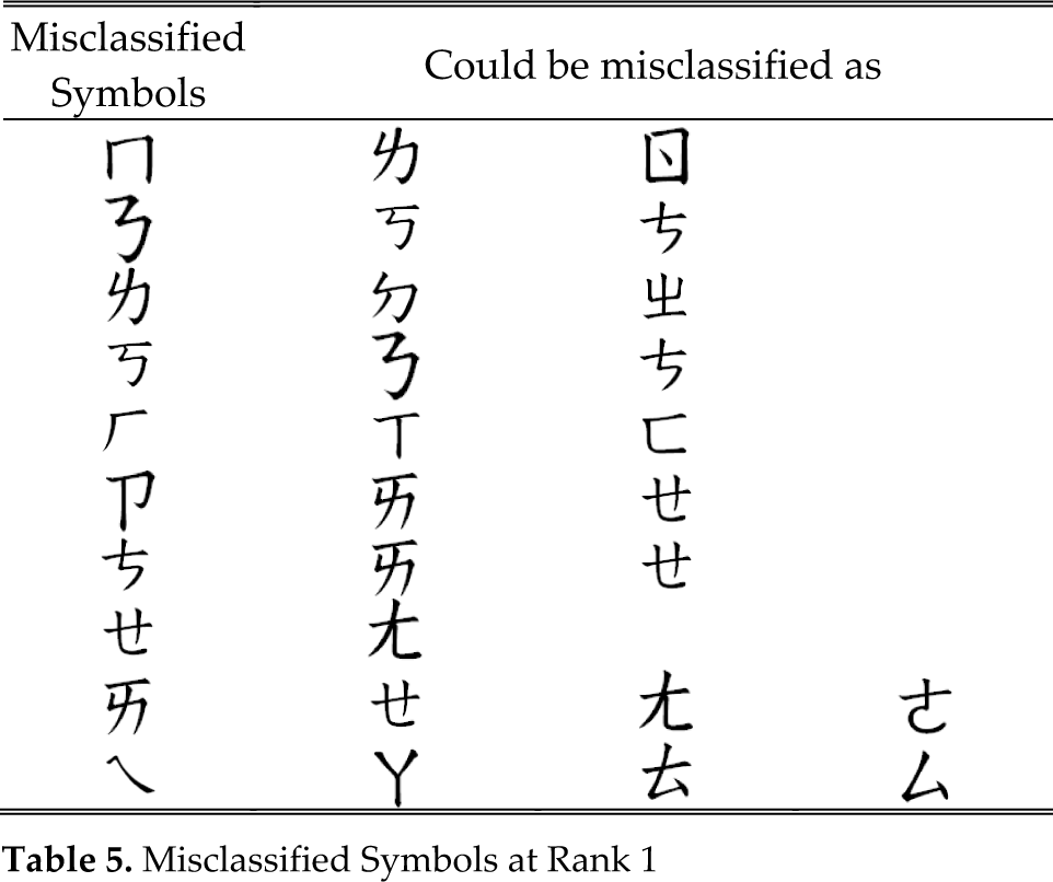
In the OCR/OLCR system, resolving the confusion set is an unavoidable problem. Table 5 shows the list of misclassified symbols in our work. It is noticeable that the symbols  and
and  are totally dissimilar in their appearance. However, they have quite similar IFD code sequences, which would confuse the trained HMMs. Generally speaking, the recognition rates using HMM are satisfying at rank 3. We believe that with the further enhancement of the confusion symbol verification procedure, high recognition rates that support practical usage can be achieved.
Misclassified Symbols at Rank 1

5. Conclusions
This paper designs an online fingertip tracking method with video-based Chinese input applications. In this framework, users employ their fingers as the input device instead of using pens or keyboards. Unlike other languages based on alphabets, Chinese character input systems are more challenging because of their logographic nature. Although this paper focuses on Mandarin Phonetic Symbols, the concept of the proposed video-based fingertip input method can also be applied to other general input systems. In this work, a particle filter with an enhanced appearance model is used to track the target fingertip. The tracked trajectories are first coded by Inter-Frame Directional coding. After locating the turning points and strokes of the input, the entering and leaving strokes are eliminated so that the recognition process would not be affected by these unstable virtual strokes. Because the real-strokes and virtual-strokes are all mixed up when using a camera as the capturing device, solving the entering and leaving strokes is a crucial task. Next, the Inter-Frame Directional code of each trajectory is analysed by Hidden Markov Models for Mandarin Phonetic Symbol recognition. From the experimental results, we verify the performance of the proposed system. We believe that the proposed input interface has high potential and can be applied to various devices.
Footnotes
6. Acknowledgements
This work is supported by National Science Council of Taiwan under project code NSC101–2221-E-008-017-MY3.