
Abstract
This paper presents an optimal control method based on control effort minimization for a legless piezo capsubot. The capsubot is an underactuated nonlinear dynamics system which is driven by an internal impact force and friction. Here, the motion mechanism of the capsubot is divided into two stages. In the first stage, the aim is to design an optimal controller minimizing energy consumption. In the second stage, optimization is not an objective and instead a four-step strategy for inner mass of the capsubot is proposed. Then, based on the proposed motion strategy, a trajectory profile is given. Using this trajectory profile, the capsubot moves in the desired direction. To evaluate the performance of the proposed control scheme, a comparative study has been performed by means of simulation. Simulation results show that the proposed approach is promising as compared to the Open-Loop Control (OLC) approach and Close-Loop control (CLC) approach which are widely used in the literature for control of capsubots.
1. Introduction
Recently, due to enormous advances in science and technology, autonomous mobile robots have attracted researchers' attention [1], [2], [3]. A capsubot is a type of autonomous mobile robot which can explore fields inaccessible to humans and transmit useful data for analysis [4]. In medical applications, some tiny capsules can be equipped with a miniature camera and can be taken down by the patient to diagnose diseases while causing less pain [5]. In general, two types of capsubots exist: legged capsubots and legless capsubots. The former has an external driving mechanism outside the capsule [6], [7] while the latter is driven by an internal impact force and friction [9], [10]. The disadvantage of the legged capsubot is the complex structure of its mechanism which makes the control difficult in rigorous environments [8]. On the other hand, the legless capsubot has a simple motion structure and can be positioned precisely in a complex environment. While the problem of the design and driving methods of the legless capsubot have received the attention of the researchers, the problem of optimization and control of the legless capsubot has not received the attention it deserves [4]. Optimal control is playing an increasingly important role in the design of modern systems. This method aims to maximize the system efficiency and minimize the predesigned cost function [11].
A seven-step motion strategy in control of capsubot systems is proposed in [4]. With this strategy, three control approaches are investigated: the Open-Loop Control (OLC) approach, the Closed-Loop Control (CLC) approach using the partial feedback linearization technique and a Simple Switch Control (SSC) approach. Moreover, a variable structure control of a capsubot system is proposed in [5]. In [12], positioning control of a capsubot using sliding mode control is designed because of its robustness to parameter changes. An iterative learning control scheme was designed for a capsubot in [13] and a classic model predictive control approach for a time delay capsubot system is presented in [14] which uses a linearized model for predicting system behaviour. In [15], a four-step acceleration profile for the inner mass of a capsubot system is proposed.
In this paper, the modelling problem of a legless capsubot is investigated. Then optimal control is used to reduce the energy consumption in the capsubot motion. Based on the cost function considered for the optimal control strategy, we can see that less energy is consumed as compared to the OLC and CLC approaches in [4]. In addition, the input force is smoother than the variable structure control in [5], sliding mode control in [12], iterative learning control in [13]and the model predictive control approach in [14].
The remainder of this paper is organized as follows.
Section 2 gives a dynamic model of the capsubot. In Section 3 the motion mechanisms and idea of control are proposed. Controller design is proposed in Section 4. In Section 5 simulation results and the test results are presented. Section 6 concludes the paper.
2. Capsubot dynamics model
The schematic of the capsubot system is shown in Fig. 1. This capsubot has three main parts: the first main part is the capsubot shell with mass

Structure schematic of the legless scapsubot system.
Using Newton's second law, the following relation is obtained

The inner mass of the capsubot is obtained in a similar way

where
Substituting (2) in (1) and rewriting it gives

Therefore

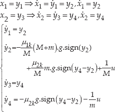
The legless capsubot is an underactuated system because it has one control input generated by the piezoelectric part while the legless capsubot has two variables – the capsubot shell position and the inner mass position have to be controlled. Therefore, we obtain the state space equations of the system as
3. Motion mechanism
In this section, the motion mechanism of the capsubot is presented. Here, the motion mechanism of the capsubot is divided into two stages. In the first stage, the fast backward motion of the inner mass leads to forward motion of the capsubot. In the second stage, the slow forward motion of the inner mass leads to no change in capsubot movement. The aim of this paper is to design an optimal controller which minimizes energy consumption in the first stage of the motion mechanism.
3.1 Capsubot forward motion mode, t∊[0; t2)
In this stage, the main goal of the capsubot is to move forward. In this mode, two phases are defined.
Phase I: In this phase, acceleration of the capsubot is positive.
Phase II: In this phase, acceleration of the capsubot is negative.
1. Phase I,

2. Phase II,

We assume that the capsubot velocity is zero at the end of this phase (
3.2 Stationary mode,
t
∊ [
t
2; t 3):
In this stage, optimization is not an objective; however, the following conditions are satisfied:
Inner mass returns to the initial condition.
Capsubot during this mode does not move.
This mode includes four phases as follows [5]:
Phase I,
Phase II,
Phase III,
Phase IV,
4. Control design
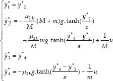
The sign-function used in (5) is not continuous which creates difficulties in differentiation and solving the optimal control problem. Therefore, we use the function tanh(y/ε), ε→0, instead.
A control input

where
The system state equations are as follows:

Using the Hamiltonian definition [11] we can write

where
Using (5) and (6) we can obtain

The necessary condition for optimality can be obtained as

where (

Therefore, the necessary conditions and boundary conditions for the first stage are obtained as follows:
Hence, we let

The above nonlinear equations are solved by numerical methods (run in MATLAB Ver.7.12.0.635).
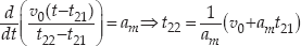
In stage 2, the partial feedback linearization control approach is used [4]. So, in stationary mode the desired velocity of the inner mass (ẏ3d(t)) can be written as [5]:

For calculating the parameters in the desired velocity profile, we have
Due to the continuity in the velocity of the inner mass, we can write

and


In this phase, the maximal deceleration (-
The initial and final velocity of the inner mass are ω0 and zero respectively. In phase II, the maximal acceleration (

So, from (5), we can write

Using the partial feedback linearization control approach, the control law can be selected as follows [16]:

where

Let

Applying (13) to (11) gives the error equation; it is quite easy to show that the closed-loop system is characterized by the error equation
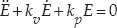
The value of
5. Simulation results
In this section, capsubot movement is simulated in two cases. In Case 1, Open-Loop Control (OLC) and Close-Loop Control (CLC) are used with parameters given in [14] and in Case 2, the proposed optimal control strategy is used. In this paper, it is supposed that the static friction coefficient is about twice the kinetic friction coefficient. Thus, μ
1s
Parameters of the simulated capsubot system.

To compare the OLC, CLC [4], and the optimal control approaches with each other, we must consider the same displacement for them. Because the capsubot displacement in the OLC and CLC approaches are the same, we use a figure to depict displacement of the capsubot in CLC and OLC. So Fig. 2 shows the capsubot motion in one cycle using OLC and CLC, and Fig.3 shows the capsubot motion in three cycles using optimal control.

Trajectories of the capsubot positions in one cycle using OLC and CLC.

Trajectories of the capsubot positions in three cycles using optimal control.
As depicted in Fig.2 and Fig.3, the amount of displacement using the OLC and CLC approaches are equal to the optimal control approach in the same time interval.
Fig.4 and Fig.5 illustrate the capsubot velocity and the inner mass velocity respectively using both OLC and CLC approaches. Fig.6 and Fig.7 show the capsubot velocity and the inner mass velocity respectively using optimal control.

The capsubot velocity in one cycle using OLC and CLC.
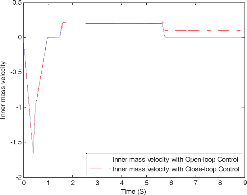
The inner mass velocity in one cycle using OLC and CLC.

The capsubot velocity in three cycles using optimal control.

The inner mass velocity in three cycles using optimal control.
Comparing the performances of these three controllers for the same displacement, it is obvious that the capsubot and the inner mass velocities using the optimal control approach are smoother than the OLC and CLC approaches. In addition, the absolute peaks in the former approaches are more than the latter one.
The forces generated by piezoelectric element in OLC, CLC and optimal control are shown in Fig.8, Fig.9 and Fig.10, respectively.
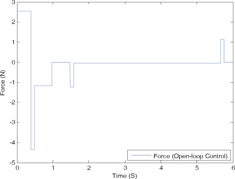
Force used in the OLC in one cycle.
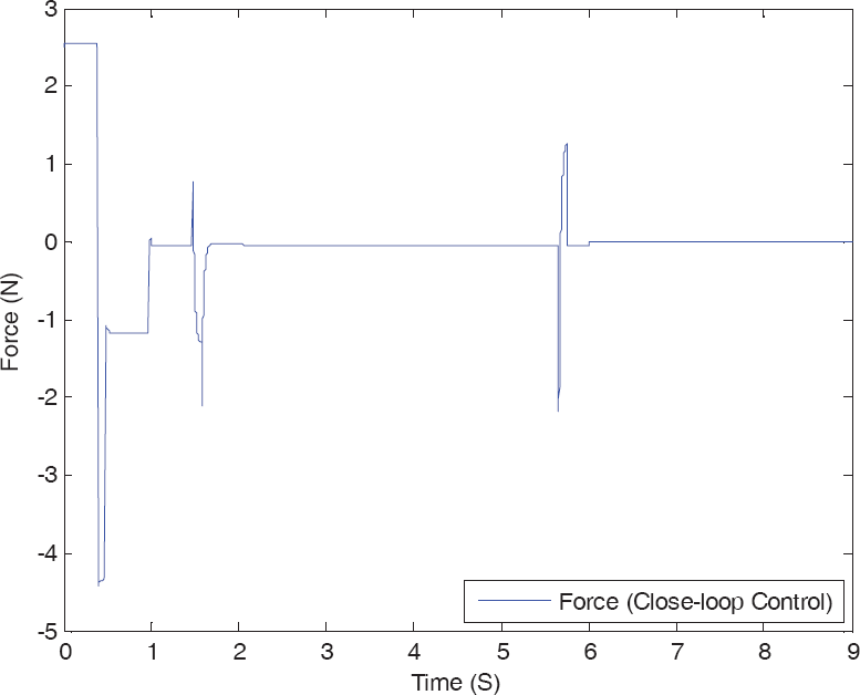
Force used in the CLC in one cycle.

Force used in the optimal control in three cycles.
Energy consumption can be calculated as follows:
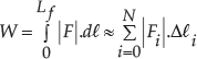
where
6. Conclusions
This paper presented an optimal control approach for the capsobut system. Simulation results show a significant improvement in smoothness and energy consumption in the proposed approach leading to selection of cheaper piezoelectric element as an actuator.
Further work on this field includes robust control with parameter uncertainty and disturbance, adaptive control with extended parameter uncertainty, and testing of the device in a real complex environment.