
Abstract
In this paper, a stabilized feedback control is designed for a class of unicycle non-holonomic mobile robots. The approach is based on kinematic polar coordinate transformations. The suggested control scheme allows the robot to achieve stabilized near-optimal trajectories, while satisfying the hard constraints of specified initial and final postures (positions and orientations). Simulation experiments showing the effectiveness of the proposed technique are provided and discussed.
1. Introduction
Recent advances in robotics have led to higher complexity in these systems from several perspectives, including stochastic identification, adaptivity and stabilizable feedback control design, in order address the primary challenges faced by today's engineering research community [1–5]. This paper considers the stabilizable feedback control design problem of a unicycle mobile robot. The roots of this problem date back to the pioneering work of Dubins [6] who set the problem of characterizing the shortest path for a particle moving forward with a constant linear velocity. This simple kinematic model opened the way for many researchers into the trajectory planning problems of robotic systems. In [7] the authors considered the same problem, where backward motions were allowable. A shortest path synthesis of Dubins' car has been determined according to Pontryagin's Maximum principle in [8].
These results have been extended in [9] to a case where obstacles are present. Clothoid-like approaches have been proposed by many researchers for path preserving curvature continuity. In particular, this approach has been used as a CAD tool in [10–12]. In strongly non-linear, coupled mechanical structures, obstacle avoidance and high velocity and precision tasks, these approaches fail to give acceptable results [13, 14].
On the other hand, non-holonomic systems have velocities subject to non-holonomic constraints. Such constraints come up in locomotion applications such as wheeled mobile robots and cannot be transformed to pure configuration constraints. For an overview of modelling and control of non-holonomic systems, see [15]. Compared to holonomic ones, non-holonomic systems are much more difficult to control.
Recently, more advanced techniques have been introduced [16–19] in which several optimization methods have been implemented in the multi-objective control of wheeled mobile robots. In [16] a summary of developments in the control of non-holonomic systems is provided. The article provides an accessible presentation of the area, with various models, problem formulations, approaches and results in a proper context. This overview provides a good introduction to the subject
In this paper, we focus on a feedback control system of wheeled mobile robots involving geometric transformation from Cartesian to polar coordinates. The main objective is to achieve stable feedback control, allowing the robot to move from a given initial to a final posture including position and orientation. In Section II the system model is introduced. Section III contains the control law for transformation into polar system coordinates. Section IV provides with simulation results and discussions and finally Section V concludes this work.
2. Modelling
2.1. Kinematic and dynamic analysis
The main problem addressed in this work is posture stabilization. Consider an open 2D area, with no obstacles, as the workspace of the robot (Fig. 1). An initial and desired final configuration (posture) of the robot would be given as:
Two-Wheeled Unicycle Mobile Robot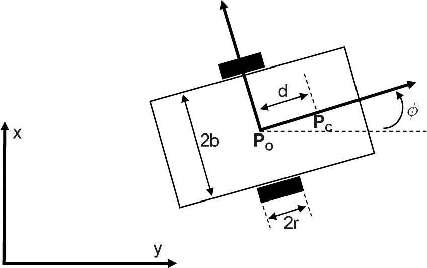
The non-holonomic kinematic constraints are given as:

(with r as the radius of the wheel).
Let us have a full rank matrix

The previous equation gives us the kinematic relation:

Differentiating

with:
as corresponding matrices.
One can reorganize then such that:

Without loss of generality, one can drop the bar notation to obtain:

The previous equations give us the following expression: (One can see also Refs. [2, 3])

To simplify even more, an auxiliary input u can be formed through feedback linearization as:

The input law in (4) when substituted in (3) will give us system equations in the form of [16–19]:

It is known that for posture stabilization [21–27], Brockett conditions [28] should be satisfied. So a conventional smooth feedback control scheme cannot solve for stabilization. The dynamic model of this system consists of both the kinematic relation and the decoupled “2nd-order inputs”, i.e., the acceleration inputs. Furthermore, the wheel velocity inputs of the kinematic relation can be transformed into unicycle velocity inputs of linear velocity υ and angular velocity ω. The transformation is a one-to-one relation that can be applied interchangeably. With this relation, one can have the same system dynamics with only a geometric change in inputs. Therefore, a complete kinematic model can be described as:


One also can view the above model in this form:

2.2. Polar coordinates based model
The control design with polar coordinate mapping is considered here. It is carried out to fulfil Brockett conditions and to provide natural motion solutions, as will be shown. Also, polar solution provides continuous smooth behaviour throughout the whole process except at the origin (i.e., the target). The control law of polar coordinates has a singular point in the origin [15]. However, this should not be a problem when adopting the method, as it is enough to approach only the region very near to the target.
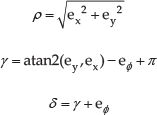
For the posture vector of ν

We can see that ρ resembles the distance from the origin of the environment frame to the origin of the robot frame, γ is the angle that the robot's frame makes with the environment (fixed) frame and δ is the rotation angle of the robot body inside its frame. The

With the new variables in the polar space, a control law is derived to stabilize the system to the target with

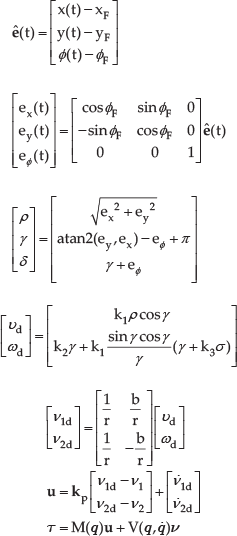
Now, let the error vector be transformed into the target frame as:
One can have the polar-coordinate error transformation as:
With the defined error variables
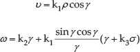
With
3. Control Law design
3.1. Acceleration inputs
Until now, we have only considered the kinematic solution for posture stabilization. However, the dynamic model of the robot includes inputs for linear and angular accelerations rather than velocities [29–30]. To design the acceleration inputs, the robot's linear and angular velocities must become extra system states. The complete system would then be as:

To stabilize the above system, but now with acceleration inputs rather than velocities, the problem does not need a special feedback design to compensate for the new 2nd-order introduced dynamics. A solution for this is to have the new inputs computed as:

With
Also,
3.2. Torque inputs
The ultimate goal of this study is to stabilize robot states trajectories and stabilize torques trajectories. So, with auxiliary acceleration inputs attained, a static relation is used to find the torques. The velocities of right and left wheel

So the auxiliary inputs can be designed as:

with the desired velocities of
The torques trajectories are computed by:

Therefore, a complete control scheme for the posture stabilization of a non-holonomic unicycle mobile robot to a target of
The above feedback law will allow target attainment and generates the torque commands as an output.
4. Numerical Simulations
4.1. Simulation set up
The stabilization law is tested for several initial and final positions and orientations. The overall goal of this stage is to have complete wheel torque trajectories that drive the robot system from different initial positions and orientations to different final positions and orientations. Three simulation scenarios will be presented here. Consider an open 2D environment of

Wheeled mobile robot e-puck (Courtesy by http://mobots.epfl.ch/e-puck.html)

4.2. Simulated scenarios
Three scenarios were considered:
This case is selected as the basic test for the control law. One can see that the initial position and orientation resemble a normal setting. The final position and orientation is selected with different orientation than the initial one in order to see the manoeuvre. The first plot of Fig. 3 is the planar view of the motion, with path shown by the dotted line and orientation evolution shown by solid lines tangent to the path.

Simulated results for the first scenario, (a) (x, y) motion, (b) Error on (
The second plot shows the error trajectories for all the posture variables of x-, y-coordinates and orientation. The third plot shows the torques variations of both wheels. The torque effect is shown for a shorter time than the motion's time, as the torque effect ends early.
This case includes a backward manoeuvre carried out by the robot and instructed by the control law (Fig. 4). Further comments are mentioned at the end of this section.
Simulated results for the second scenario (a) (x, y) motion, (b) Error on (
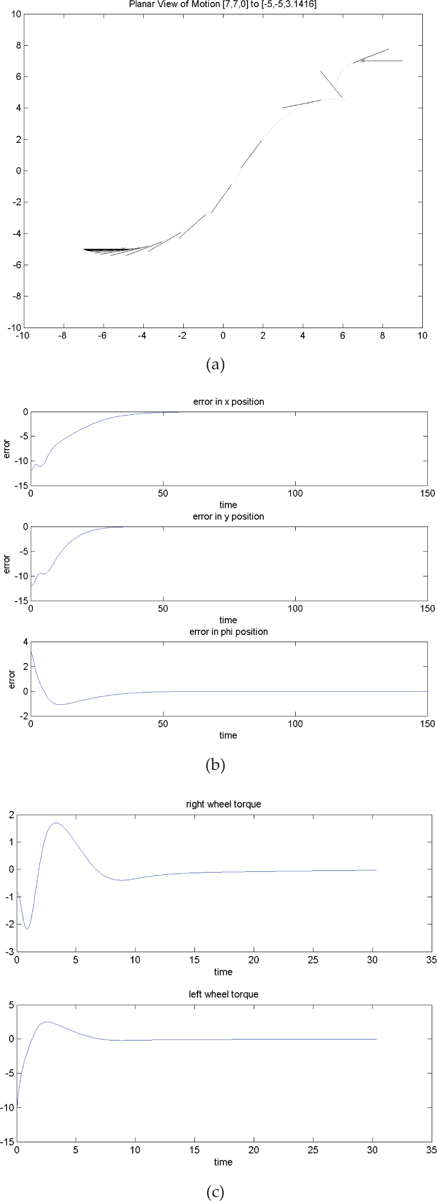
This case includes a rather harder manoeuvre (Fig. 5), as is obvious from the first plot. Also, one can observe the sharp turn carried out at the beginning of the motion.

Simulated results for the third scenario, (a) (x, y) motion, (b) Error on (
4.3. Discussion
The feedback controller based on polar coordinates gives good and natural results.
The discontinuity at the origin (target) did not limit the solution performance.
Most of the energy is spent by the wheels in a relatively small time. This should be overcome in further improvements to optimize the process and distribute the energy throughout the motion. This task is being processed as part of on-going work. Part of these problems was treated in the context of motion planning and offline programming in [31–32].
5. Conclusions
In conclusion, this paper presents a control law for a unicycle non-holonomic mobile robot. The control law stabilizes the robot with satisfactory results. The constraints on the input torques are not enforced at this stage. That is why relatively high initial torque values can be seen. This is expected as the feedback law principle dictates it. The solutions are a good initialization of the work, in terms of objective satisfaction, namely non-holonomic constraints, reaching a target, the apparent smoothness of the trajectories and the easy reproduction of any settings. The future target is to generalize this to a multi-objective system, involving energy and time minimization, limitations on input torques and obstacle avoidance.
Footnotes
6. Acknowledgements
The authors gratefully thank King Fahd University of Petroleum and Minerals for supporting this paper under grant #FT100029.