
Abstract
Sound source localization based on a microphone array for mobile robots faces great challenges because of factors such as uncertainty of the robot's movement, noise and reverberation, the requirements of a compact microphone array and so on. This paper studies a method for sound source localization in a dynamic environment using a cross-microphone array plane, which consists of four microphones on an intelligent mobile robot platform. Firstly, the method of spectral subtraction and campestral mean normalization is introduced to de-noise. Then GCC-PHAT-ργ and the guided spectral-temporal (ST) position method are proposed to suppress noise and reverberation based on the generalized cross-correlation method to estimate time delay. Finally, the sound source is positioned by adopting the geometric location method. This system is tested by a total of 2,016 sets of experiments. Even in an intensely noisy and reverberating environment, the guided ST position method achieves angle positioning accuracy of more than 95% with a less than 15 degrees localization error. Meanwhile, all the experimental data can be processed in real-time, within 0.4s.
1. Introduction
The technology of sound source localization for robots is a simulation of the human auditory system. It receives sound signals using a microphone array and other sensors which are placed on the robot. These signals can be processed in order to achieve sound source position detection, speech recognition and so on [1]. In the case of earthquakes and other catastrophic accident scenes, humans cannot effectively handle the circumstances owing to radiation and pollution. The sound source localization system of a mobile robot can have advantages in these situations and complete voice positioning tasks.
The application of sound source localization technologies has been broadly researched in the areas of mobile robots and communication technologies. Early in 1995, Robert from MIT [2] installed a simple auditory system in a robot, although the functions of this auditory system were limited. In 2006, the Honda Research Institute [3] developed a multi-source real-time tracking system through a joint of an In-Room Microphone Array (IRMA) and a microphone array embedded in a robot's head. In 2007, Valin [4] developed an obstacle-avoidance robot based on beamforming technology using an 8-channel microphone array. At the same time, Hara reported that an 8-channel system using a robot embedded microphone array (REMA) had better performance for sound source localization [5]. However, the performance is worse when the robot is in motion, because it is difficult to synchronize signal capturing with motion precisely and adapt to acoustic environmental changes during robot motion [3].
The technologies for sound source localization based on a microphone array can be categorized into three classes: (1) directional technology based on high resolution spectral estimation [6]; (2) controllable beamforming technology based on the biggest output power [7]; (3) technology based on time delay of arrival (TDOA) [8, 9]. The first method often aims at narrowband signals, but voice signals are broadband signals which need to improve positioning accuracy with high computational complexity. The second method requires a priori knowledge of sound source and environmental noise, and the computational complexity is also high. Lastly, the TDOA method has strong real-time applicability and is suitable for single speech sound source localization. Through appropriate improvements to overcome noise and reverberation, it can achieve better positioning accuracy.
The TDOA method is generally referred to as a two-step method: the first step estimates the time delay of each pair of microphones. Then, using the geometric positioning method, the second step localizes the sound source based on TDOA. The generalized cross-correlation (GCC) method is a classic technique for time delay estimation (TDE) [8] and several weighting functions are also proposed. Phase transition (PHAT) weighting function sharpens the peak of time domain cross-correlation function by pre-whitening the cross-spectrum of signals, which improves the performance of TDE to a certain extent when environmental noise and reverberation exist. This algorithm has low computational complexity and is easy to implement. However, if environmental noise and reverberation is too large, the accuracy of TDE will decline significantly. Generally, it estimates single time delay, which indicates that it cannot be applied to multiple sound sources.
Sound source localization using the TDOA method for mobile robots faces difficulties when the following arise: (1) people speak continuously, the robot moves, room reverberation [10] changes simultaneously (which needs accurate reverberation estimation and good real-time ability [3]. (2) When a robot is in motion, the motor leads to a noise increase. An effective de-noising algorithm is needed to separate voice and noise. (3) A large size microphone array [11, 12] installed on a robot will lead to movement difficultly, so it is necessary to calculate the precise location of the source with an appropriate amount of microphones. (4) Continuous localization means robots can quickly estimate the space reverberation model for a single source and locate a number of sound sources which are generated in a short time. Obviously, the most critical factors with continuous localization for mobile robots are real-time functioning and accuracy. Localization algorithm must have low computational complexity for real-time demand and the changes of environmental reverberation must be detected in time to meet accuracy.
To address the issue of uncertainty with the parameters of ST position [13], this paper produces guidance on the ST position method and designs a novel guided ST position algorithm based on the GCC-PHAT-ργ method to get prior knowledge, such as the rough location of the sound source, changes of environmental reverberation, etc. It is proved that the detection of sound location is strong in real-time for mobile robots using a 4-channel microphone array. Our contributions are as follows:
A new weighting function PHAT-ργ for the generalized cross-correlation method is proposed to suppress the impact of noise.
A guided ST position method is proposed combined with the PHAT-ργ method to reduce reverberation and determine accurate location of the sound source by the mobile robot. For sharpening the peak of cross-correlation function, the segmentation of the frequency slices were weighted in the guided ST position method.
A microphone array model and general structure are introduced for a mobile robot to improve the positioning accuracy and correspond to the speed and walking routes.
A continuous real-time location system is achieved while the robot is in motion and a game named ‘hide-and-seek' is used to verify the compatibility, robustness and efficiency of the system.
This paper is a revised and expanded version of a paper entitled ‘Continuous Sound Source Localization Based on Microphone Array for Mobile Robots' presented at the IEEE International Conference on Intelligent Robots and Systems (IROS2010) held at Taipei, Taiwan [14].
The rest of this paper is organized as follows: section 2 describes the model of the microphone array. De-noising techniques, and the PHAT-ργ and guided ST position methods will be described in section 3. In section 4 experimental results and analysis are shown, and conclusions are drawn in section 5.
2. Microphone array structure
The design of a microphone array on a mobile robot relates to the following issues: (1) the amount of microphones; (2) the shape of the microphone array; (3) the distance between two microphones; (4) the features and properties of the robot. Firstly, too many microphones are inconvenient for robot movement and hence increase the complexity of the algorithm. By contrast, if too few microphones are used, the positioning accuracy cannot be guaranteed. Secondly, for omnidirectional azimuth localization, the microphone array should be approximately isotropic on the horizontal plane. Finally, it has been found that the distance between the microphone pair should be in a certain range. For example, assuming the distance is 0.1m, the sampling rate is 44100Hz and the sound velocity is 340m/s, the maximum sampling point difference will be 0.1×44100/340=13, which concludes that the average resolution of this microphone pair is 180°/26=6.7°. Taking the TDE error into account, this resolution is too bad for sound source localization. Therefore, the microphone spacing cannot be too small. On the other hand, because of the constraints of the size of the robot platform and the far-field assumption, microphone spacing cannot be too large. Paper [15] shows that when the microphone distance b and the distance r from sound source to the centre of the microphone array satisfy the relationship r/b>3, the quantization angle error is less than 0.4°. As shown in Figure 1, our microphone array is composed of four microphones with a cross-shaped plane. Any one microphone pair in this array can be used to calculate the time difference of sound transmitting from the sound source to these two microphones. For safety the relative distance between robot and speakers must be preserved, the minimum of r is 1m. According to the relationship r/b>3 and the robot size, the distance between two microphones is set to 0.4m.

Microphone array
3. Guided ST position algorithm
The GCC-PHAT-ργ method is based on the non-reverberation model. It cannot detect the speakers correctly in a directional interference noise environment. The robot's motor generates directional interference, therefore, this section introduces a de-noising algorithm and proposes a method named guided ST position to eliminate noises, room reverberation and calculate the location of the sound source in real-time.
3.1. De-noising Algorithm
The signal that microphones receive is mixed with noise when noise interference exists. The noises which the robot faces consist of the robot's body noise, changing ambient noise at different working scenarios, etc. Body noise comes from the mobile robot's motor and the environmental noises in this paper include air-conditioning noises and some kinds of weak outdoor noise (car engine sounds, voices, etc.). These noises can be considered as short-sighted steady additive noise. The spectral subtraction and cepstral mean normalization methods [16] are applied to remove noise. By estimating the noise power in each frame and subtracting it from the total power spectrum, the spectral subtraction method can estimate the pure audio power spectrum, while the phase of clean speech frame is replaced by the phase of noisy speech. Cepstral mean normalization is also applied to the de-noising algorithm. Its goal is to eliminate bias in the cepstral domain caused by convolution noise. Moreover, it can also deal with background additive noise to a certain extent. The block diagram of the de-noising algorithm is shown in Figure 2.
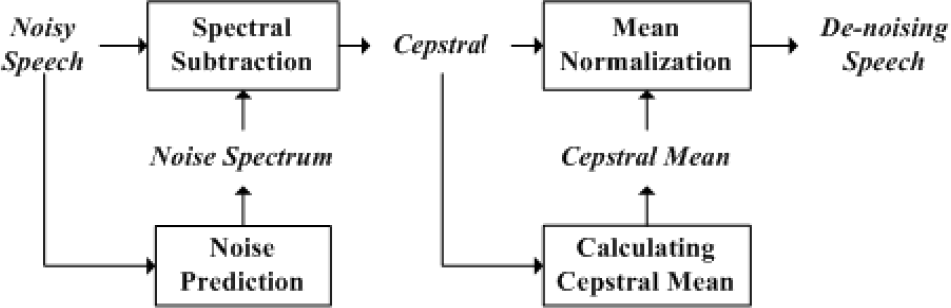
Block diagram of the de-noising algorithm
Taking advantage of this de-noising algorithm, Figure 3 gives the de-noising effect of noisy speech in the time domain. It can be seen that the de-noising algorithm can effectively remove the background noise and has little effect on the signal distortion.

Time-domain waveform diagram
3.2. GCC-PHAT-ργ Method
For the classic time difference of arrival algorithm, such as the GCC method, the peak position of the cross-correlation function is the relative delay between two signals. Firstly, the algorithm calculates the cross-power spectrum and gives a certain weight to curb the impact of noise and reflection in the frequency domain. Then the cross-correlation function is obtained through transforming the cross-power spectrum to time domain. Suppose the sound source signal is s(t). The position of m-microphone is

where

where

where the independence between signal and noise is supposed.
The phase transform (PHAT) weighting function can be expressed as

It can improve positioning accuracy by using the modified weighting function in the PHAT-ργ method in small SNR and large reverberation situations.
3.3. Guided ST Position Algorithm
The PHAT-ργ method is an effective algorithm and it has strong real-time efficiency. However, the time delay will have more errors when noise and room reverberation are more serious, which worsens the localization performance of angle and distance of sound source. The guided ST position method based on the PHAT-ργ method can solve this problem. Firstly, the GCC-PHAT-ργ method is used to determine the approximate location of the sound source. Then, based on the priori knowledge of the room reverberation estimated from the approximate location, a local estimate method is applied to estimate the exact location of the sound source. In this method, a local estimate with ST position weighting function is applied. The difference of this method to GCC is that GCC is weighted to the entire voice, while the local estimating method calculates the cross-correlation function for every cell of voice segment separately.
Paper [15] proposed a new weighting method named spectro-temporal position (ST position). As the voice segment has more than one cell, the i-frame and j-band is denoted by c(i, j). Cross-correlation functions of all cells are calculated and weighted using the ST position method. Finally, the time delay information of each cell is super positioned to form the final time delay.
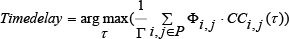
Where P is the set of i, j and Γ is the number of elements in P. Φ, CC and τ are the weighting function, cross-correlation function and time difference of cell c(i,j), respectively. Q is defined as the cross-correlation coefficient in every cell. Q is mainly dependent on two factors, namely, frequency f and the distance from starting point of voice segment s. The cell becomes more reliable when its Q-value increases and meanwhile, more resistant to room reverberation. When the cell is getting close to the starting point of the voice segment, the proportion of direct voice in this cell is bigger and the same as its Q-value.
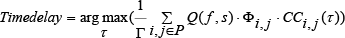
However, this method has a problem that Q-value is unpredictable during operations performed by the algorithm. It needs to statistic using pre-training data and this increases the limitations of the algorithm, which indicates that it will be invalid when the acoustic environment of sound source varies. GCC-PHAT-ργ can obtain the approximate relative position of the sound source and the robot, which is used to roughly estimate the sequence of voice signals received by different microphones and the reverberation environment. By using the known location, the sound source signal can correct the SNR value and determine the correct frequency chip, and the frequency of on-chip with SNR to be ranked. According to the different SNR, Q-value is set. Instead of lots of statistics, it just needs a Q-value determined by the relative standards, such as Q-value limited in the range of 0-1. The Q-value of those voice sections that are close to the starting point is close to 1, otherwise, Q-value tends to 0. It is a novel approach to take advantage of this approximate location of sound source to determine the Q-value without advance statistics. The weighting function is changed as,
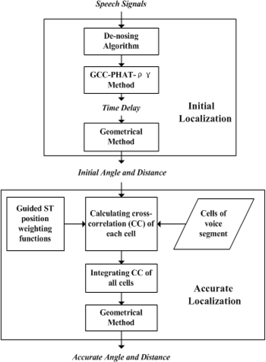
Flow chart of the guided ST position algorithm
Figure 4 is the flow chart of the spectral segmentation algorithm, which consists of two parts: the initial localization gets the approximate angle and distance using GCC-PHAT-ργ. The accurate localization uses the guided ST position method which calculates the cross-correlation function for every cell of voice segment separately. Different cells have different weighting functions and coefficients Q. Here, Q has a relationship with frequency f and the distance from the starting point of voice segment s. The biggest problem with this method is that Q-value is unknown during operation and needs to statistic using pre-training data. Then the sequence of voice signal received by different microphones and the reverberation environment of a robot are estimated using the rough sound source location, so that the Q-value can be achieved by the guided ST position method.
4. Experiments and analysis
4.1. Configuration of Experimental Environment
The mobile robot works in a hall of 8m×8m, which is a semi-indoor environment. Our scene graph of the robot and microphone array model is shown in Figure 5.

Mobile robot and microphone array
Four BSWA MPA416 microphones and a MARIAN TRACE8 multi-channel audio sample card are used for the sampling of sound. In addition, the data sampling rate will largely affect the performance of localization. However, a higher data sampling rate means that more data points need to be analysed and computational complexity will increase. Therefore, this system selects the data sampling rate of 44.1kHz. The microphone array is placed on the shoulder of the robot with a height of 1m. Given that the height of the mouth of a standing adult is about 1.5m, the plane of the microphone field is chosen as the standard when evaluating the localizing performance on the horizontal plane and all the localizing results have to be projected to this standard plane. The robot is placed in the centre of the hall, with another 72 points in the floor as testing sound sources. The sound sources are evenly distributed at every 15 degrees and three positions in each direction, with a distance of 1, 2, 3m from the centre, respectively. The following three groups of highly-targeted experiments are designed to test the performance of our method precisely. Figure 6 shows the plane diagram of the robot and sound source points.
4.2. Static Experimental Results
First, in order to test the real-time ability and accuracy of the algorithm, we set the single localization and multiple positioning experiments for the static robot. The robot is fixed in the centre of the hall. The 72 points to be tested are shown in Figure 6 and 28 sets of data are collected

Plane diagram of robot and sound source points
for each point, in total 2,016 groups of data. The content of voice can be an arbitary word, such as “positioning”, “PengPeng”, “hello”, “note” and so on, and it is verified that the performance of sound source localization is irrelevant with the content. Three different SNR environments are tested, namely SNR is 10, 25, 40dB.
Single angle localization results

Table 1 shows the angle localization accuracy of the three algorithms with different SNR, in which the localization error is less than 15 degrees. Because of the width of the human body, sound source will produce the equivalent of obstruction reflection, which will be reflected off some of the walls into the microphone. Its impact on the direct sound reflection is greater than the wall, thus allowing for error in the 15 degrees range is feasible. It can be seen that the PHAT-ργ weighting function improves the localization accuracy. Moreover, the guidance spectral segmentation method gets the best performance. All of the experiments are achieved in time, within 0.4s. In particular, the performance of 2m is better than others, which can be attributed to the better far-field characteristic and better recording condition.
Multiple angle localization results

Table 2 shows the multiple positioning accuracy of angle for three algorithms with different SNR, in which the localization error is also less than 15 degrees. In the application of human-robot interaction, if incorrect localization results occur, re-positioning is a reasonable method for rectifying this. If the robot fails to locate the sound source, the speaker will re-call a word from the same position. This experiment still tests the 2,016 sets of experimental data mentioned above. Compared with single localization, it can be seen that the accuracy of two consecutive positions is much better, which can largely avoid the occasional error of the first localization. The guided ST position algorithm obtains localization accuracy of up to 99.55% with SNR 40dB for the case of 2m, which is very accurate for human-robot interaction.

Localization results and errors of the GCC and guided ST position methods
It is easy to observe the angle localization results and localization error of the GCC method and spectral segmentation algorithm from Figure 7, respectively. The abscissa presents the real angle value. The average value of 84 groups of experiments is used for each angle. It can be seen from the figure that the angle localization performance of our algorithm is better than the GCC method, and the localization error of our algorithm is very small, which meets the system requirements.
The distance localization results of guided ST position with SNR 10dB are shown in Table 3, which concludes four kinds of localization error, namely the difference between the localization value and the real value is less than 0.3m, 0.5m, 0.8m and 1m. It can be seen that localization errors of distance are almost less than 1m, which can be effectively used for human-robot interaction to a certain extent. However, more work should be done to improve the performance.
Distance localization results

4.3. Dynamic Experiments of Human-Robot Interaction
A game named ‘hide-and-seek' is designed for this robot for continuous localization which combines speech recognition and hand detection technology. In a room of 64m2, the robot is located at the centre of the room as the starting point and three people or more stand around it. It can recognize spoken orders such as “localization”, “turn left” and so on. When the robot moves according to the orders, the people located in the different places put up their hands and call “localization”, the robot could find the sound direction and turn to the person. When it faces the person directly, the camera will detect the people who put up their hands and move towards him/her. Figure 8 shows the hide-and-seek experiment between robot and human. However, owing to the different height of speakers, the mouth of speaker couldn't keep the height of 1.5m. Moreover, there exist measurement error of the real value of speaker's position. Therefore, localization error is inevitable. However, from an experimental point of view, these errors are permitted in a controllable range. The experimental results mentioned above show that 90% of the data had angle errors less than 25 degrees. As our camera's detection range is ±23 degrees, sound source can be accurately located using audio-visual fusion mechanisms.

Interface diagram of “hide-and-seek” between the robot and humans
5. Conclusions
In this paper a speech source localization method is proposed for a mobile robot, which uses single voice or multiple voices to locate the angle and distance of a speaker. The movements of the robot and human always change the acoustic environment, which should be taken into consideration. A new weighting function for generalized cross-correlation, named PHAT-ργ, is proposed to suppress noise. Based on the time delays estimated by GCC-PHAT-ργ, the geometrical position method can calculate a rough location of sound source, which is used for modelling a more exact acoustic environment, including noise and reverberation. The guided ST position method is used for accurately locating the angle and distance of sound source through the more exact acoustic environment model. The results of our experiments demonstrate that this system provides better performance in aspects of localization angle, and real-time and audio-visual fusion.
Footnotes
6. Acknowledgments
This work is supported by the National Natural Science Foundation of China (NSFC, No.60875050, 60675025), National High Technology Research and Development Programme of China (863 Programme, No.2006AA04Z247), Scientific and Technical Innovation Commission of Shenzhen Municipality (No.JC201005280682A, CXC201104210010A).