
Abstract
Collaborative tasks between human operators and robotic manipulators can improve the performance and flexibility of industrial environments. Nevertheless, the safety of humans should always be guaranteed and the behaviour of the robots should be modified when a risk of collision may happen. This paper presents the research that the authors have performed in recent years in order to develop a human-robot interaction system which guarantees human safety by precisely tracking the complete body of the human and by activating safety strategies when the distance between them is too small. This paper not only summarizes the techniques which have been implemented in order to develop this system, but it also shows its application in three real human-robot interaction tasks.
1. Introduction
Robotic manipulators are increasingly widespread in current industries [1] due to their positional precision, repeatability and durability. They are usually applied in repetitive assembly tasks, where all the components are always in the same position and only the positional control of the robot is needed. Nevertheless, the application of robotic manipulators that can react to changes in their environment may improve the productivity of current industrial processes. In particular, context-aware robotic manipulators do not need to be completely isolated from the rest of the production line [2] and thus the cost of the manufacturing process can be reduced, not only in terms of space (by removing the current fenced robotic cells) but also in terms of time (by redefining the production processes so that many more subtasks can be performed simultaneously). In order to develop this context-awareness, robotic manipulators are gradually incorporating additional sensors which register important information from the environment in order to adapt their behaviour according to changes in it. For instance, cameras and force sensors are usually installed at the end-effector of the robot [3] in order to determine the trajectory which has to be tracked by the robot, depending on the evolution of the visual features registered by the camera (i.e., visual servoing techniques) and the contact forces/torque detected by the force sensor (i.e., force control).
This context-awareness of robotic manipulators enables the participation of new agents during the production process, such as human operators who can develop those subtasks which cannot be completed by robots. In fact, robots and humans present complementary features for the development of common tasks. On the one hand, the robot completes those subtasks which are exhausting or dangerous for the human. On the other hand, the human performs those subtasks which cannot be executed by the robot because of their complexity. For instance, humans are able to perform specialized tasks which require intelligence and dexterity. This synergy between humans and robots enables the development of more flexible and complex tasks which cannot be performed individually by a human or a robot [4]. Furthermore, the application of human-robot interaction in industrial environments can also improve the productivity of the system because the robot can continue its normal work while human operators are inside the workcell [5].
Nevertheless, in order to make possible such human-robot cooperation, it is necessary to guarantee the safety of human operators [6]. This safety requirement is imperative in human-robot interaction systems where humans cooperate with industrial robots because of their large dimensions, their weights and the high speed of their operation. In fact, collisions between humans and industrial robotic manipulators may be very dangerous for humans and they must be completely avoided.
The traditional solution to the safety problem is based on isolating the robot with physical barriers, such as fences or light curtains (i.e., optoelectronic sensors) which stop the robot immediately when crossed by a human. The first robot safety standards, such as ISO-10218:1992 [7], were based on this paradigm. The segregation between robots and humans avoids any risk of collision but significantly limits the flexibility of the task. In fact, this safety solution cannot be applied in tasks where the human and the robot must share the same physical workspace or in tasks where their completion requires collaboration.
These drawbacks have triggered the development of new safety standards which permit the coexistence of humans and robots in the same workspace under certain circumstances [8]. For instance, the standard ISO-10218-1:2006 [9], which constitutes the first part of the revision of the previous standard ISO-10218:1992, defines a group of new collaborative operation modes where purposely designed robots work in direct cooperation with humans while always respecting hard limits on maximum velocity (250 mm/s) and static force (150 N). While the standard ISO-10218-1:2006 is based on the design and construction of the robot itself, and is useful for robot manufacturers, a new standard - ISO-10218-2:2011 [10], which is now under development and constitutes the second part of the revision of ISO-10218:1992 - will determine the safety requirements for the installation of robotic cells. These standardization efforts show the increasing interest of industries in human-robot collaboration.
Several approaches have been developed in the previous research in order to implement safety in human-robot interaction tasks. The first approach is based on mechanically redesigning the robot so that it does not cause any injury to humans in cases where there is a collision. Generally, these safe robot designs include the use of a whole-body visco-elastic covering for the robot [11–12] and/or mechanical compliant joints based on cable transmissions, springs or even with flexible links [13]. Nevertheless, these compliant transmissions are rarely applied in industrial manipulators because they cause slower responses and increased oscillations that reduce the positional accuracy and the velocities of the robot. In addition, visco-elastic covers are useless for heavy industrial robots whose inertias are too high because collisions with humans continue to be too risky. Another solution for human-robot collisions is the use of motion controllers that decrease the contact forces when a collision with a human is detected by force/torque sensors installed at the end-effector and/or at the joints of the robot [14, 15]. All these techniques constitute post-collision strategies that reduce the effects of collision but which do not avoid them. Nevertheless, in industrial environments where humans collaborate with robots, the collisions should always be avoided because they can disturb the human operator while he/she is performing the task.
Therefore, the implementation of human-robot interaction tasks requires pre-collision planners which modify the trajectories of robotic manipulators depending on their distance from human operators. When this distance is too small, the planner should change the trajectory of the robot in order to avoid any risk of collision. In addition, since these systems need to track the movements of these human operators in order to compute the human-robot distance, more flexible interaction tasks can be performed by employing this contextual information. Thus, human-robot interaction tasks become more natural and unobtrusive because the trajectories of the robots are dynamically changed depending upon the human operator's movements.
This paper presents the research work that the authors have developed in recent years in order to design and implement a human-robot interaction system which fulfils all of these requirements. The proposed system is divided into two main components: a human tracking system and a human-robot distance computation system. The main contributions of these systems are presented in sections 2 and 3 of this paper, respectively. Then, in section 4, several real human-robot interaction tasks are shown in order to verify the correct behaviour of the system. Finally, section 5 summarizes the results obtained and the advantages of the proposed system.
2. Human Tracking System
2.1. Components of the Human Tracking System
As described in the introductory section, the human-robot interaction system must be context-aware and know exactly where human operators are during the development of collaborative tasks. Therefore, a precise localization of these human operators is needed. Nevertheless, most indoor localization systems only register the global position and orientation of a person but they do not consider the positions of the person's limbs. Motion capture systems do not have this drawback because they are able to measure full-body movements and thus they are suitable for human tracking in industrial environments.
Several sensor technologies are used for motion capture nowadays [16–17]: mechanical, magnetic, optical and inertial. They have different advantages and disadvantages, depending on the physical properties of each type of sensor. Mechanical systems are accurate but they are uncomfortable for daily work because their exoskeletons limit the human operator's movements. Magnetic systems are negatively influenced by the magnetic fields of industrial environments. Optical systems suffer from occlusions which reduce their accuracy, especially in cluttered industrial workplaces with huge moving objects, such as robotic manipulators. Motion capture systems based on inertial sensors overcome these drawbacks because they are comfortable due to their small size sensors, they are robust in relation to magnetic field distortions [18], and they do not suffer from optical occlusions.
Due to these advantages, a GypsyGyro-18 inertial motion capture system from Animazoo [19] is proposed to track the movements of all the limbs of the human operator. This system is composed of a Lycra suit over which 18 IMUs (Inertial Measurement Units) are attached. Each IMU is placed over a rigid segment of the human operator's body and provides the system with the orientation measurement of this segment. The combination of the orientation measurements of all the IMUs enables the system to obtain a skeletal model of the human operator where the relative positions and orientations of the bones of his body are calculated.
Nevertheless, the global position of the skeleton obtained from this system is obtained by a footstep extrapolation algorithm that accumulates small errors through time due to the inertial measurements' integration [20]. In order to correct these errors, a global localization system should be added. The authors propose adding the Ubisense localization system [21] to the human tracking system in order to solve this problem. This system is based on UWB (Ultra-WideBand) signals and it is immune to multi-path fading and radio-frequency interferences. The global position measurements of this UWB system should be combined with the measurements from the inertial system in order to get a precise estimation of the global position and orientation of the full body of the human operator. The next subsection describes in detail the fusion algorithm which has been developed in order to perform this measurement combination.
2.2. Sensor Fusion Algorithm for Human Tracking
The two components of the human tracking system have complementary features. On the one hand, the inertial motion capture system has high error values (larger than 60 cm) for the global position of the human operator while the UWB localization system obtains more accurate position measurements (with errors smaller than 15 cm). On the other hand, the sampling rate of the UWB system (with a maximum value of 10 Hz) is not high enough to track quick human movements while the inertial motion capture system supplies high data rates (30–120 Hz). This complementarity guarantees that the combination of both systems will make the most of their advantages. The position measurements of the UWB system will correct the error accumulated by the inertial system while the position measurements from the inertial system will reduce the latency of the UWB system by providing new measurements between each pair of successive UWB measurements.
A fusion algorithm [22] based on Bayesian Filtering [23] which takes into account this complementarity is developed. The proposed algorithm combines a Kalman filter [24], which is applied to the inertial measurements, with a SIR particle filter [25], which is applied to the UWB measurements. Figure 1 shows a general scheme of the structure of this Kalman-particle filter fusion algorithm.
The prediction step of the Kalman filter adds a Gaussian noise to the previous state estimate
Each time a UWB measurement

General scheme of the Kalman-particle filter fusion algorithm
This fusion algorithm obtains better global position estimates than previous systems where a Kalman filter or a particle filter are individually applied [22]. The fast measurements of the inertial motion capture system can be easily represented with the linear Gaussian models of a Kalman filter, while the slow measurements of the UWB system are better modelled with a non-linear non-Gaussian technique (such as a particle filter) because of their high latency. The use of the efficient Kalman algorithm for inertial measurements improves the computational performance of the fusion algorithm in comparison with other fusion algorithms, which only apply particle filters to all measurements [26–28]. The use of the particle filter in order to correct the inertial error when UWB measurements are received improves the precision of the position estimates in comparison with previous fusion approaches, which only apply Kalman filters to all measurements [29–31].
3. Human-Robot Distance Computation System
3.1. Hierarchy of Bounding Volumes
As described in the introductory section, the developed human-robot interaction system should modify the behaviour of the robot based upon the human-robot distance. In order to compute this distance, the authors propose a new system which uses a hierarchy of bounding volumes as an efficient representation of the surfaces of the robot and human bodies. Each limb of the human body and each link of the robot structure is covered with a SSL (Sphere-Swept Line) bounding volume [32]. This kind of bounding volume has been selected because it provides a good relation between the precision of the spatial representation and the computational cost of its pairwise distance calculation. In fact, SSLs provide a very tight fit for cylindrical links [33] in comparison with previous approaches based on spherical representations [34–35].
Nevertheless, a total of 144 pairwise distance tests are required each time the minimum human-robot distance is calculated, since there are 18 SSLs for the human operator (2 for the feet, 2 for the legs, 2 for the thighs, 1 for the abdomen, 1 for the thorax, 1 for the neck, 1 for the head, 2 for the shoulders, 2 for the arms, 2 for the forearms and 2 for the hands) and 8 SSLs for the robotic manipulator (1 for each link of the robot, including the base and the end-effector). In order to reduce this number of distance tests, the authors propose the use of a hierarchy of bounding volumes with three levels. Table 1 shows the components of the hierarchy of bounding volumes of the human operator and Table 2 shows those of the robotic manipulator.
Hierarchy of bounding volumes for the human operator

The third level of this hierarchy is composed of the SSLs bounding volumes described above, and it is only used when the human-robot distance is very small. The second level is obtained by covering several of the SSLs of the third level with an AABB (Axis-Aligned Bounding Box). In the case of the human operator, 5 AABBs are used: 2 for the lower limbs, 2 for the upper limbs and 1 for the torso. In the case of the robot, 3 AABBs are used: 1 for the base and the first link, 1 for the following two links and 1 for the last four links. The first level is obtained by covering the full body of the human operator with one AABB and the full structure of the robot with another AABB.
Hierarchy of bounding volumes for the robotic manipulator

3.2. Robot Controller based on Human-Robot Distance
The bounding volumes of each level of the hierarchy presented in the previous section are used to compute an approximation of the human-robot distance. First of all, the distance computation algorithm uses the first level of the hierarchy (i.e., global AABBs) and it obtains a lower threshold for the human-robot distance. If this distance is bigger than a pre-established threshold, this means that the human and the robot are far away enough to discard the other levels of the bounding volume hierarchy. As such, when they are working together, only one distance test is sufficient. If the distance computed from the first level is smaller than the threshold, then a more detailed computation is necessary and the second level of the hierarchy (i.e., local AABBs) is used. Next, the system computes the distance between each local AABB of the human operator and each local AABB of the robotic manipulator and then establishes as the human-robot distance the minimum pairwise distance value between all these computations. If this distance is bigger than a second pre-established threshold, this distance value is considered as sufficiently precise and thus only 16 pairwise distance tests (1 test for the first level and 15 tests for the second level) are required. Finally, if the distance computed from the second level is smaller than the second threshold, the third level is applied and 144 distance tests between the SSLs are executed.
Accordingly, this hierarchical organization of the bounding volumes drastically reduces the number of distance tests and improves the computational cost of the distance computation algorithm by adapting it to the required distance precision. The distance precision is established by the values of the thresholds which determine the use of the different hierarchy levels. The first threshold represents the distance where the robot and the human are too far away from each other such that that they are considered to work independently. The second threshold identifies the distance where the human approaches the workspace of the robot and a precise distance computation is required in order to guarantee human safety.
The minimum human-robot distance computed from the hierarchy of the bounding volumes is used by the robot controller in order to change the robot's behaviour. In fact, when the human-robot distance is bigger than a safety threshold, the robot controller works normally and the robot performs its normal task. This normal task usually involves the tracking of a trajectory by visual servoing [37] and/or the development of physical interaction subtasks by force control [38]. When the human-robot distance is smaller than the safety threshold, a risk of collision may occur; the normal behaviour of the robot is stopped and a special safety strategy is executed. The authors have implemented two different safety strategies for the development of human-robot interaction tasks. The first strategy completely stops the robot's motion whenever the minimum human-robot distance is smaller than the safety threshold. The second strategy moves the robot away from the human operator in a linear path, so that the human-robot distance is kept above the safety threshold. Depending upon the type of human-robot interaction task, one or the other is used.
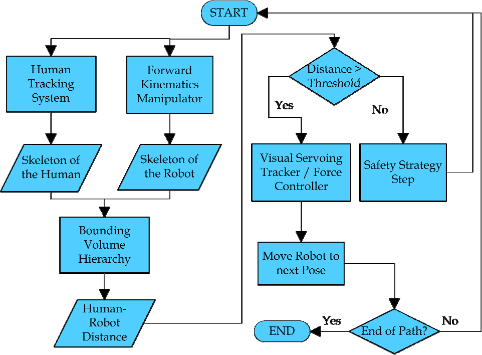
General scheme of the robotic controller
Figure 2 depicts the main components of this robot controller which are executed at each iteration. Firstly, the position and orientation of the skeletons of the human and the robot are updated from the human tracking system and the forward kinematics, respectively. Then, these skeletons are covered by the corresponding bounding volumes and the minimum distance between them is calculated by applying the hierarchy of bounding volumes previously described. This distance value is compared with the safety threshold. If it is bigger, the normal behaviour of the robot is executed and its end-effector is moved towards the following pose of the planned trajectory, which has been calculated by visual and/or force control. If the distance is smaller than the safety threshold, the safety strategy is executed. The following section describes in detail three different collaborative tasks where this controller scheme has been applied.
4. Human-Robot Interaction Tasks
The human-robot interaction system described in the previous sections has been applied to three assembly and disassembly tasks in order to verify its correct behaviour: the disassembly of a street-lamp for bulb replacement, the disassembly of an electrical appliance, and the assembly of a metallic structure.
4.1. Disassembly of a street-lamp for bulb replacement
The first human-robot interaction task involves the replacement of a blown light bulb in a street-lamp with a new one. The main elements that constitute this task are as follows: the street-lamp whose light bulb needs to be replaced, the Mitsubishi PA-10 robotic manipulator which replaces the light bulb, and the human operator who brings the new light bulb and the storage box where the blown light bulb is stored. The Mitsubishi PA-10 robotic manipulator has three devices installed at its end-effector in order to perform the task: a three-fingered Barrett hand, a JR3 force sensor and an eye-in-hand Photonfocus MV-D752-160-CL-8 camera. This camera is used to track four laser points projected on the floor, which are the extracted visual features for the visual servoing path tracking system which controls the normal trajectory of the robot. The human wears an Animazoo GypsyGyro-18 suit and an Ubisense UWB tag in order to be tracked.
This task can be divided into the following phases, which are shown in Figure 3:
Disassembly of the street-lamp (Figure 3a): The robotic manipulator grasps the spherical light diffuser of the street-lamp with the Barrett hand and turns it until it is released from the base. This moment is detected by a change in the force/torque pattern of the end-effector force sensor. Then, the robot leaves the light diffuser over the floor in order to gain access to the blown light bulb.
Transportation of the blown light bulb (Figure 3b): The robot unscrews the blown light bulb and detects its release from the base by analysing again the force/torque pattern of the end-effector force sensor. Next, a visual servoing path tracker is used in order to guide the robot towards the storage box where the bulb has to be placed.
Collaboration of the human operator (Figure 3c): While the robotic manipulator is executing phase 2, the human operator approaches the workspace in order to leave the new light bulb over the turning table. If the human-robot distance is smaller than the safety threshold (1 m for this task), the robot stops its normal behaviour (i.e., path tracking towards the storage box) and executes the safety strategy which moves the robot away from the human in a linear path so as to keep the distance above the threshold.
Installation of the new bulb and assembly of the street-lamp (Figure 3d): When the safety strategy ends because the human operator has gone away and the human-robot distance is again above the safety threshold, the robot completes phase 2 and leaves the bulb in the storage box. Next, it takes the new light bulb which was left by the human and screws it in the base of the street-lamp. All of these subtasks are performed by executing a visual servoing path tracker in order to drive the robot towards the street-lamp and a force control for determining the end of screwing activities.
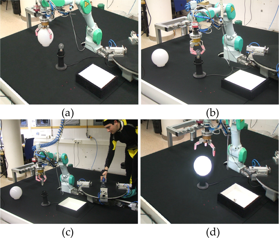
Phases of the disassembly task of a street-lamp
Figure 4 depicts a group of frames during the execution of phases 2 and 3 of this task. Firstly, the robot begins to track the trajectory between the street-lamp and the storage box by applying visual servoing. This trajectory is marked by green points in Figure 4a and Figure 4b. When the human operator enters the workspace and approaches the turning table in order to leave the new light bulb, the safety strategy detects that the human-robot distance is below 1 m, stops the path tracking at the red point of the trajectory shown in Figure 4c, and activates the safety behaviour so that the robot moves away from the human (as shown in Figure 4d). When the human operator moves away from the workplace, the visual servoing path tracking is activated again. This path tracking moves the robot to the last visited position of the trajectory (as shown in Figure 4e) and then visits the remaining points of the trajectory (as shown in Figure 4f). Figures 4a, 4b and 4f show at their right upper corners the skeletons registered by the human tracking system and the robot controller. Figures 4c, 4d and 4e show the 3D error between the real position of the robot end-effector and the desired position from the initially planned trajectory.

Sequence of frames where the safety strategy is activated during the execution of the task
4.2. Disassembly of a home appliance
The second human-robot interaction task aims to disassemble a home appliance (i.e., a small fridge). The main elements that constitute this task are the following: the fridge, the Mitsubishi PA-10 robotic manipulator which unscrews the fridge lid, the human operator which extracts the internal tray of the fridge and the storage box where the different parts of the fridge are stored after they are disassembled. The Mitsubishi PA-10 robotic manipulator has three devices installed at its end-effector: a screwdriver, a JR3 force sensor and an eye-in-hand Photonfocus MV-D752-160-CL-8 camera. The image trajectory is generated by using four laser points projected on the floor as the extracted features for the visual servoing path tracking system. The human operator wears the GypsyGyro-18 suit and the UWB tag.
The disassembly task can be split into the following subtasks to be performed by the two agents:
Robot subtask: The robotic manipulator has to remove the screws of the rear lid of the fridge. Firstly, the robotic manipulator goes from the storage box towards the unscrew position by applying the visual servoing path tracking system. Secondly, the robot unscrews the four screws, one by one. Finally, it removes the rear lid in order to leave it in the storage box.
Human operator subtask: The human operator has to empty the contents of the fridge in order to make the disassembly process easier.
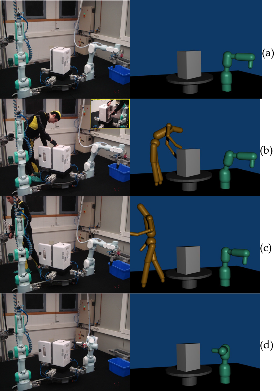
Sequence of frames of the home appliance disassembly task
These two subtasks are executed simultaneously. Figure 5 shows a sequence of frames of the execution of this task and the 3D representation of the bounding volumes of the third level of the hierarchy. First of all, the robot is guided by a visual servoing path tracker in order to go to the unscrew position over the fridge (see Figure 5a). During this tracking, the human approaches the fridge, the safety behaviour is activated and the robot goes away from the human in order to keep the distance above the safety threshold while the human operator opens the fridge door and empties its contents (see Figure 5b). While the human operator is moving away from the robot (see Figure 5c), the human-robot distance is again greater than the safety threshold and the visual servoing path tracking is reactivated. Afterwards, the path is tracked correctly and the robot can arrive at the unscrew position by following the predefined path (see Figure 5d).
Figure 6 shows the evolution of the computed human-robot distance and how the system is able to keep this distance above the safety threshold (1 m in this case) when the human approaches the robot.

Evolution of the human-robot distance in the home appliance disassembly task
4.3. Assembly of a metallic structure
The third human-robot interaction task involves the assembly of a metallic structure where two robotic manipulators and a human operator cooperate. The metallic structure is composed of cylindrical tubes which are connected by metallic connectors. The two Mitsubishi PA-10 robots will handle the metallic tubes while the human operator will screw the connectors, since it is a very difficult task for a robot. The first robot R1 has a two-jaw pneumatic gripper for handling tubes, a JR3 force sensor for detecting any collisions of tubes and an eye-in-hand Photonfocus MV-D752-160-CL-8 camera for tracking the path between the storage box and the turning table where the structure is to be assembled. The second robot R2 has a Barrett hand to hold the tubes which will be screwed by the human operator. The human operator will wear the same tracking system.
The task can be divided into the following three phases:
Tube handling (see Figure 7a): One of the manipulators extracts a tube from the storage box while the other manipulator handles a tube with the Barrett hand so that the human can screw its ends. This manipulator will not move throughout the execution and thus the safety strategy is not applied to it. Meanwhile, the human operator prepares the connectors outside the manipulators' workspaces.
Fist T-connector screwing (see Figures 7b and 7c): The human operator enters in the manipulators' workspaces and begins to screw the first T-connector to the tube which is held by R2. Meanwhile, the first manipulator continues approaching the metallic structure by applying visual servoing in order to insert the tube which was extracted from the storage box. During this phase, the human-robot distance goes below the safety threshold (0.5m in this case) and the safety strategy is executed. The robot R1 stops the path tracking procedure and moves away from the human operator in a linear path so that the distance is kept above the threshold (as shown in Figure 8).
Second T-connector screwing (see Figure 7d): After screwing the first T-connector, the human operator picks up the other T-connector and walks around the workspace until reaching the other end of the tube in order to screw it. In this case, the human-robot distance is always above the safety threshold. Therefore, robot R1 resumes its path tracking task and inserts the tube into the structure. When the robot ends the tube insertion and the human finishes screwing the connector, the task finishes.
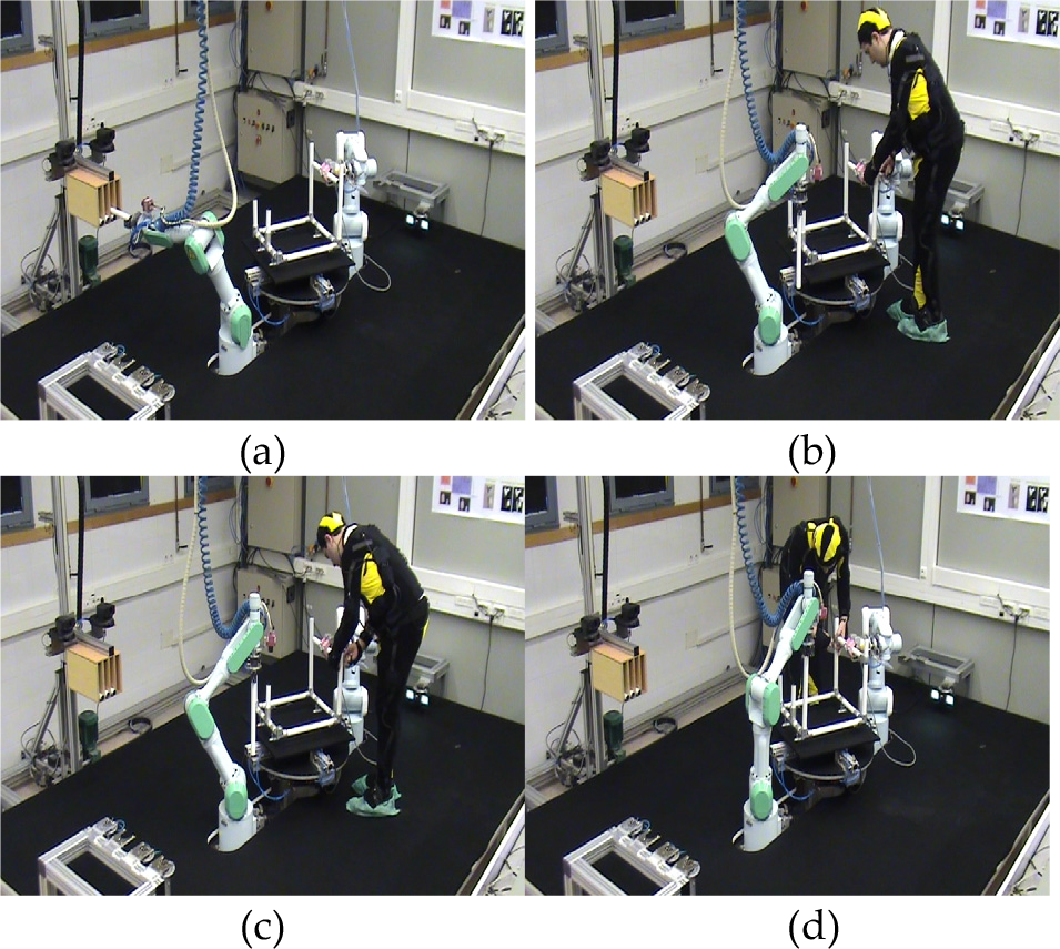
Sequence of frames of the metallic structure assembly task

Evolution of the human-robot distance in the metallic structure assembly task
5. Conclusions
This paper presents a human-robot interaction system which can be used to develop collaborative tasks between human operators and robotic manipulators in industrial environments. The main components of this system are: a human tracking system and a robot controller based on human-robot distance. The human tracking system achieves a precise localization of the complete body of the human operator by combining the measurements of an inertial motion capture suit and an UWB localization system. The robot controller applies the measurements from this tracking system and the joint values of the robot over two skeletal models of the human and the robot in order to represent the poses of their complete bodies during the development of the task. These skeletons are covered by a hierarchy of bounding volumes and then the minimum distance between them is computed. This minimum distance is used to change the behaviour of the robot when it is too close to the human and where collision may occur.
This system has been successfully applied in three different assembly and disassembly tasks in order to show its applicability: the disassembly of a street-lamp, the disassembly of a home appliance and the assembly of a metallic structure. In all of the three tasks, the system was able to guarantee human safety by executing a safety strategy when the human-robot distance was too small.
Footnotes
6. Acknowledgments
The research leading to these results has received funding from the European Community's Seventh Framework Programme (FP7/2007-2013) under Grant Agreement no. 231640 and the project HANDLE. This research has also been supported by the Spanish Ministry of Education and Science through the research project DPI2011-22766.