
Abstract
The bolting cabin assistance system prevents operators from facing dangerous situations. This system consists of a bolting robot control system and a top view supervisory system. In order to control the bolting robot, circular Hough transforms and fuzzy reasoning are used. First, the circular Hough transform roughly estimates the location of the bolt hole. After that, errors of estimation are compensated for using fuzzy reasoning. In order to track a bolt hole, a region of interest (ROI) is used. By setting the region in which to search for a bolt hole, the algorithm tracks the location of the bolt hole. In order to choose an ROI, a template-based matching algorithm is used. In order to make the top view supervisory system, four cameras are installed at the left, right, front and back of the robot. The four individual images from the various cameras are combined to make the top view image after correcting for distortion.
Keywords
1. Introduction
In the construction field, workers can encounter many dangerous situations. The bolting robot helps workers work safely and can reduce the prevalence of such hazardous situations. This paper presents the concept of the bolting cabin and proposes the bolting robot control algorithm using circular Hough transforms and template matching to estimate the location of the bolt hole, an error compensation algorithm using fuzzy reasoning and a top view supervisory system that can observe the cabin from multiple angles. The bolting robot control system helps workers in assembling bolts safely. In vision-based bolt hole tracking, “bolt hole detection” is the key technique to estimate the location of the bolt holes. Circular Hough transforms and template-based matching are used to identify circles in the images. The circular Hough transform belongs to the set of feature-based matching algorithms. Feature-based matching uses the edges of shapes and intensity of particles to recognize an object. However, these features are not recognized by a camera in low illumination conditions. In contrast to feature-based matching, even though template-based matching is not affected by illumination conditions, it cannot perform accurate recognition. To overcome such shortcomings, this paper suggests an illumination-robust detection algorithm using the mixed matching algorithm. The mixed matching algorithm has merits compared to feature-based matching or template-based matching. As the raw image is affected by radial distortion, it is difficult to extract the bolt hole from the raw image and to estimate the location of the bolt hole. To deal with these problems, fuzzy reasoning is used.
The top view supervisory system provides video imaging that can observe the cabin from various angles. As previously mentioned, the raw image is distorted. In this paper, a radial distortion correction algorithm, a perspective distortion correction algorithm and an image combination method are proposed.
2. Related work
Various robots have been developed for construction, such as a fireproofing spray robot, robot crane and a tool-developing robot [1-3]. An approach to modularize house-building and an assembly robot have been proposed, and a large-scale unmanned construction project was tested in Japan [4,5]. Since the development of high-tension bolts, the bolting method has been preferred to construct high-rise steel structures. However, it is difficult to automate the bolting process. Consequently, human workers still climb the vertical steel beams on top of high-rise steel structures at construction sites, as shown in Figure 1. The manual process is time-consuming, inefficient and extremely dangerous. To resolve this problem, bolting cabins and bolting cabin assistance systems are proposed in this research which can provide an automated bolting process.
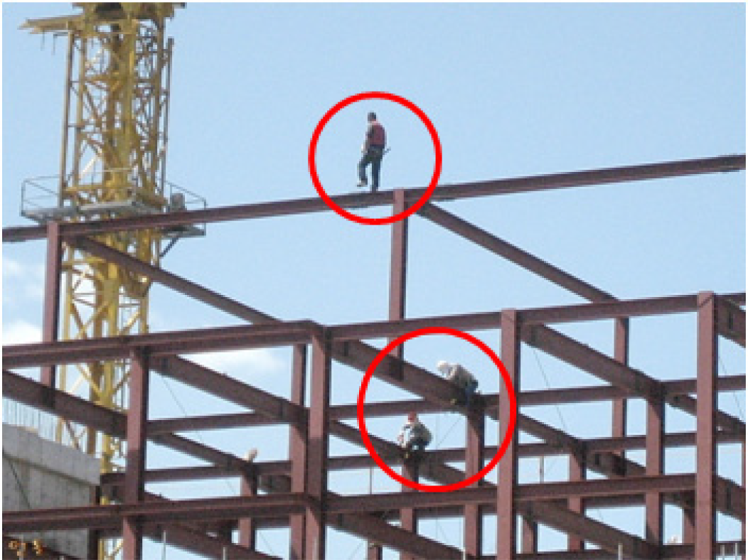
Bolting work in high places 3. Concept of the bolting cabin
3. Concept of the bolting cabin
The bolting cabin system consists of a bolting robot and cabin. The cabin is a mobile robot that moves on a construction site and a bolting robot is a tool that performs bolting work. To perform bolting work, the bolting robot control system was developed, and to guarantee the safety of workers in the cabin, the workers can observe the area around the cabin using a top view supervisory system. Figure 2 shows the bolting cabin system.

Bolting cabin system
4. Bolting robot control system
4.1 Organization of the bolting robot
The bolting robot consists of a camera, laser range finder, gantry robot and bolting tool. Figure 3 shows the bolting tool system. Using the camera, the bolt hole is extracted from the image. Using the extracted bolt hole location and the laser range finder, the gantry robot can calculate the appropriate position for fitting the bolt. Once the gantry robot is in position, the bolting tool performs the bolt-related operations.
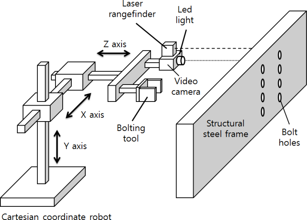
Organization of the bolting robot

Template-based matching

Estimation of the bolt hole radius
4.2 Template-based matching
Template-based matching is one of several pattern recognition techniques used to find a desired object that is similar in size and shape to a given template. For the similarity measurement, the sum of absolute differences (SAD) and the sum of squared differences (SSD) are widely used in various applications [6,7]. In addition, the normalized cross correlation (NCC) measurement is also popular for similar measurements. NCC is more robust than SAD and SSD changes under illumination [8]. In this paper, an NCC algorithm is used.
4.3 Circular Hough Transform
The Hough transform is a feature extraction technique used in image analysis, computer vision and digital image processing [8]. The purpose of this technique is to find imperfect instances of objects within a certain class of shapes by using a voting procedure. This voting procedure is carried out in a parameter space, from which object candidates are obtained as local maxima in a so-called accumulator space, which is explicitly constructed by the algorithm for the computation of the Hough transform. The classical Hough transform was concerned with the identification of lines in images, but later, the Hough transform was extended to locate the positions of arbitrary shapes, most commonly circles or ellipses. The circular Hough transform has been widely used to extract circles and ellipses. Its main disadvantage is that the computational complexity of the algorithm increases according to the dimensions of a shape. If the radii of the circles are known, the complexity of the algorithm can be reduced [9]. Using a laser range finder, we can calculate the radii of the circles.
4.4 Estimation of the radius of a bolt hole
R is the radius of a circle in an image plane. We should estimate R. Let f, d and r denote the focal length (f), the camera centre to frame distance (d) and the radius (r) of the hole in the steel frame. We can obtain reliable data for each parameter using the laser range finder. We can derive a proportional Eq. (1) with given parameters f, d and r.

4.5 Compensation of lens distortion
Images captured by real cameras suffer from lens distortion, which is a blend of perspective and radial (barrel) distortion [10]. Distortion is inherent in all images taken through lens systems [11]. These kinds of distortions cause errors when images are processed. In this paper, radial distortion is taken into consideration.
To solve this problem, image stretching is generally used. Figure 6 shows a distorted and corrected image.

Distorted and distortion-corrected image
However, when using a corrected image, an additional calculation is needed, thereby slowing down the total processing speed. Moreover, it decreases the image resolution and contrast of the raw image.
In order to compensate for lens distortion, this paper suggests fuzzy reasoning based on Hartley's radial distortion model [12].


In Eqs. (2) and (3), distortion coefficient L(r) is determined by r(r >= 0, L(0) = 1). The distortion coefficient L(r) is approximated by the Taylor expansion [13].

Distortion coefficient L(r) decreases with the distance from the centre.
Figure 7 shows circle distortion caused by barrel distortion. In the centre of the image, the circle is not distorted, however, circle distortion increases with the distance from the centre. This results in an inaccurate distance calculation that can lead to inaccurate input data for the robot.
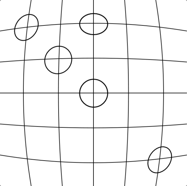
Circle distortion caused by barrel distortion
The best way to compensate for circle distortion is to estimate the error at each pixel. Error means the difference between the distance calculated using Eq. (1) and real distance from the image centre to the centre of the circle. However, this approach is too time- and effort-intensive to be practical.
Thus, another approach is suggested, using fuzzy reasoning [14-16].
First, calculate L(r) using previous research results [17]. Second, divide the image appropriately by L(r) and estimate the distance error within each divided section. Figure 8 shows an image divided by L(r) and Tables 1 and 2 show L(r) and the estimation error at each line.
Left side vertical line

Upper side horizontal line
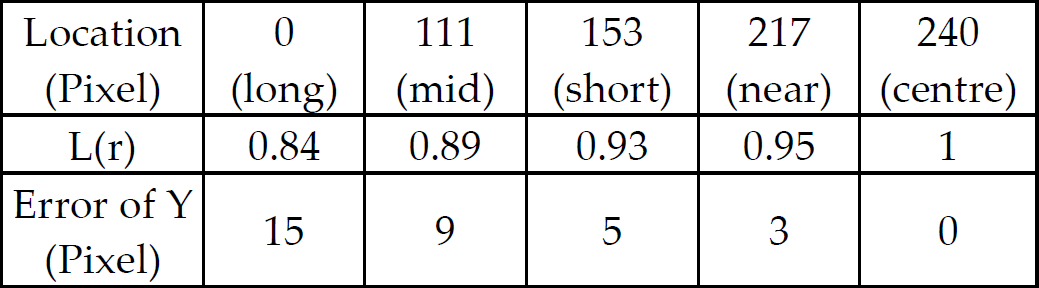

Image (640 × 480) divided by L(r)
L(r) and the error of each line are symmetric with respect to the origin. The error of a pixel refers to the difference between the location of a line in the distorted image and the location in the real image. Using these results, the error of every pixel is estimated using fuzzy reasoning. Figure 9 and Table 3 show the use of the fuzzy membership function and the fuzzy rule (left upper side). The estimated distance of a point to its origin is used as a fuzzy set.
Fuzzy rules for pixel compensation


Fuzzy membership function
4.6 Experiment and result
Figure 10 is a block diagram that shows the complete bolt hole tracking process.

Block diagram of the bolt hole tracking process
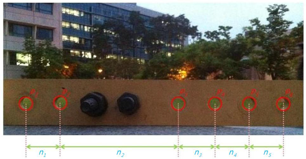
Experiments were done using Template Matching (TM), circular Hough transform (CHT), compensated circular Hough transform (CCHT) and mixed matching (MM) algorithm. Figure 11 shows the extracted shapes of the bolt hole circles and their relative distances.
Table 4 contains the difference between the real distance and the estimated distance between the centres of the two circles.
Estimated and real distances

Table 5 shows the difference between the real diameter and the estimated diameter of each circle. These tables show the average error of each algorithm. Template matching showed the worst results. The circular Hough transform and the compensated circular Hough transform show better results.
Estimated diameter and real diameter

To compare the compensated circular Hough transform and the mixed matching algorithms, an experiment was performed 30 min after sunset. Figure 12 shows the results of bolt hole extraction after sunset using the mixed matching algorithm and Figure 13 shows the extracted shapes from Figure 12.

Arrange symbols of circles and compute distances

Result of bolt hole extraction using the mixed matching algorithm
Extracted shapes from Figure 11
Tables 6 and 7 show the estimated distances between each circle using the compensated circular Hough transform and the mixed matching algorithm.
Distance between each circle using the compensated circular Hough transform

Distance between each circle using the mixed matching algorithm

When comparing Table 6 to Table 7, the results of Table 6 show huge errors and variance. This means that the compensated circular Hough transform is unsuitable and the mixed matching algorithm proved to be much superior to other algorithms tested.
5. Top view supervisory system
The top-view supervisory system helps the operator in observing the bolting robot from various angles. Using this system, the operator can prevent accidents and the ensuing stress regarding the unseen area can be significantly reduced. In this study, four wide-angle cameras are installed at the front, back, left and right sides of the bolting robot. Each image from the respective cameras is used to make the combined top-view image after distortion (barrel, perspective) correction. Figure 14 shows a block diagram of the top view supervisory system.

Block diagram of the image processing steps
5.1 Organization of the top view supervisory system
To make the top view image of the robot, a wide-angle camera is mounted at the top of the robot. The captured images from the four cameras at various angles are combined into one image via 4 by 1 MUX. The combined image is input into a vision PC by a grabber. The input image is processed by the vision PC. Figure 15 shows the organization of the system.
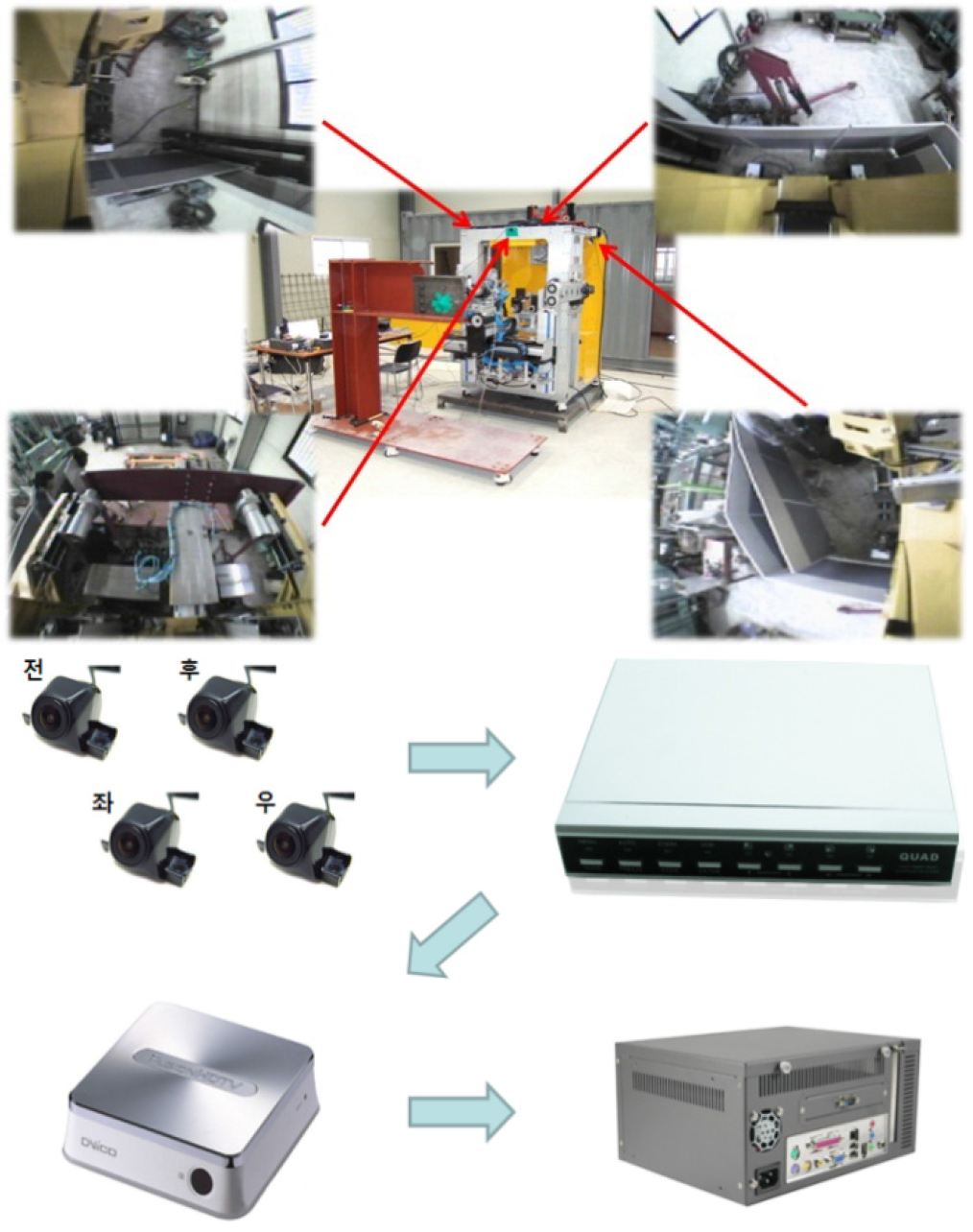
Organization of the system
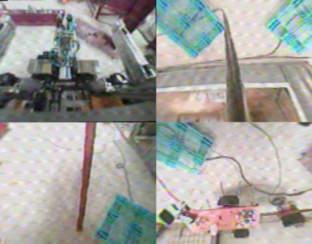
The captured images from this process are shown in Figure 16. The top-left part is the front, the top-right is the back, the bottom-left is the left and the bottom-right is the right view of the robot. This image has both radial and perspective distortion. Using these raw images, a top view supervisory image is made.

Captured raw images
5.2 Radial distortion correction of captured images
The radial distortion correction algorithm is handled in Section 2.5
Figure 17 shows the radial distortion correction image. In contrast to the raw image, the curves of the image have been transformed to straight lines.
Radial distortion correction image
5.3 Perspective distortion correction of the image
It is impossible to accurately depict a 3D reality on a 2D plane. Perspective distortion is determined by the relative distance at which the image is captured and viewed, and is due to the angle of view of the image being either wider or narrower than the angle of view at which the image is viewed, hence the apparent relative distances differ from what is expected. Figure 18 shows a perspective distortion situation wherein parallel rails converge at a vanishing point.
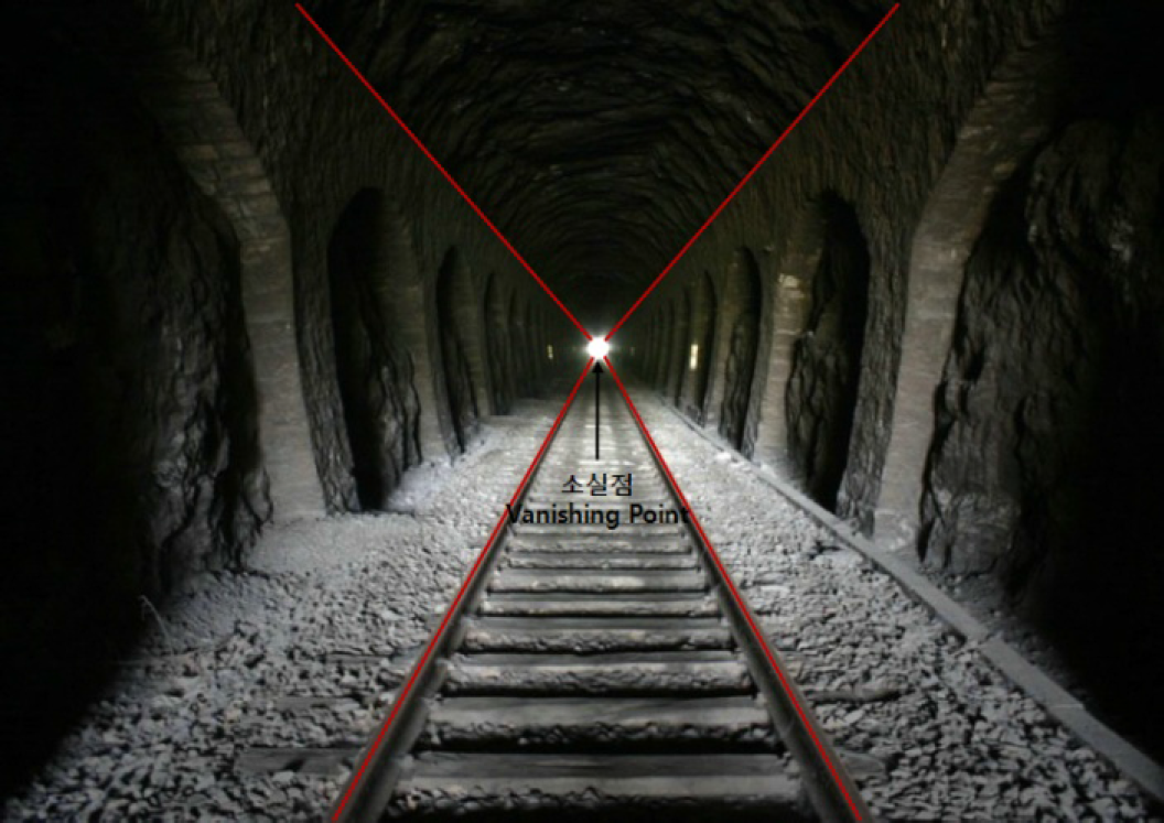
Convergence of parallel rails at a vanishing point
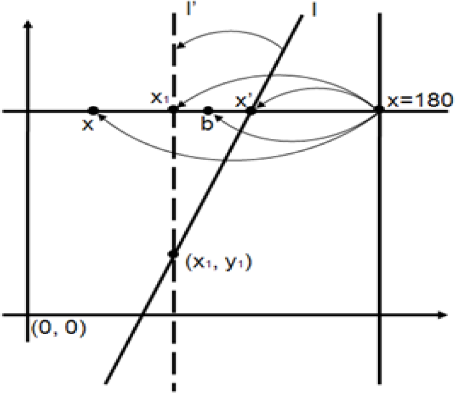
To correct perspective distortion, the image is stretched with respect to the vanishing point. A formula for distortion correction is given as follows:
To correct line l that is leaning toward the vanishing point, l is transformed to l'. (x1, y1) is a rotation axis of line l. Point x́ is a point on the line l, í is the correction line of line l, point x is an arbitrary point in the image and point b is the corrected point.
The equation of line l is described as Eq. (4) and point x́ on line l is described as Eq. (5).


Corrected point b is derived from Eq. (6).


Using the previous results, Figure 20 shows the distortion corrected images.
Perspective distortion correction

Distorted and distortion corrected image
5.4 Combination of the distortion corrected image
To properly perceive the multi-perspective image of the robot, the distortion corrected images are appropriately combined. Figure 21 shows the selected regions displayed in the distortion corrected image.

Selected regions combined into the corrected image
Using the selected images, the top view supervisory image is stitched together and Figure 22 shows the complete top view supervisory image. In the case of the front view image, distortion is not corrected because the image is hidden by the bolting tool. For that reason, perspective distortion correction is difficult.

Top view supervisory system
6. Conclusion
In this paper, a new concept of the bolting cabin system is introduced. The bolting cabin assistance system consists of the bolting robot control system and the top view supervisory system. The bolting robot control system is a remote control system that operates the gantry robot and bolting tool, and the top view supervisory system provides the stitched-together image depicting the cabin from various angles. The bolting cabin control system can prevent workers from encountering dangerous situations. Moreover, the bolting robot can be modified to use other tools and the cabin can perform other construction tasks. Using this system, an application was developed and it is being used in the real construction field. Figure 23 shows the developed application.

Developed bolting robot assistance application
Footnotes
7. Acknowledgments
This work was supported by a Korea University Grant. The authors would like to thank the Ministry of Land, Transport and Maritime Affairs, Korea. This work was also supported in part by the High-Tech Fusion Construction Technology Development Program.