
Abstract
Directional antennas have the considerable benefits of higher antenna gain, long transmission distance and spatial reuse compared to omni-antennas. To support a directional antenna, IEEE 802.15.3c specifies a high data transmission rate and short frequency range communication based on the characteristics of 60GHz band. However, the contention-based protocol of IEEE 802.15.3c may cause channel collisions and throughput degradation as the number of stations in the network increases. In order to resolve this problem and reduce channel access latency, we propose an adaptive allocation algorithm in which the contention window size for optimal transmission probability is derived after the directional information has been obtained by means of AP control procedures. Extensive simulations demonstrate that the proposed algorithm outperforms the existing channel access scheme in IEEE 802.15.3c wireless personal area networks under different situations, especially when the number of contending stations is large.
Keywords
1. Introduction
Recently, spectrum utilization between 30 and 300 GHz has drawn considerable attention due to the possible high speeds. Because the wavelengths for these frequencies are between 1 and 10 mm, it is referred to as the millimetre wave (mmWave) band. There are currently two standards for mmWave networks, namely IEEE 802.15.3c wireless personal area networks (WPANs) and European Computer Manufacturers Association (ECMA)-387, which has been developed by the Technical Committee (TC)-48. The former is based on centralized networks [1], whereas the latter is based on distributed networks [2] aiming for more than 2 Gbps for a target data rate. In addition, IEEE 802.11ad is now standardizing; this is based on centralized networks with 7 Gbps for a target data rate [3].
The mmWave has unique characteristics such as its short wavelength, high frequency, large bandwidth and high interaction with atmospheric constituents [4]. Such characteristics are associated with many of its salient properties, such as multi-gigabits per second, which enables it to support wireless applications requiring a high data rate, such as wireless high-definition multimedia interface, wireless USB, IPTV/VoD, 3D gaming and intelligent transportation systems. On the other hand, the high interaction of mmWave radio with atmospheric constituents causes more propagation attenuation. Oxygen absorption and radio rain attenuation cause much more severe short range problems than found with other frequency bands such as 2.4 GHz or 5 GHz radio. Moreover, the mmWave signal is degraded significantly when passing through walls or over distance. Even though these radio characteristics help ensure that the content is secure, they can also cause various problems such as short wavelength and high path loss in mmWave communications.
The IEEE 802.15.3c MAC layer defines two distributed channel access mechanisms: a reservation channel access mechanism called the channel time access period (CTA) and a contention-based channel access mechanism called the contention access period (CAP). In IEEE 802.15.3c standard, the CTA section is assigned to the same fixed-size period and the same
Access category parameters set
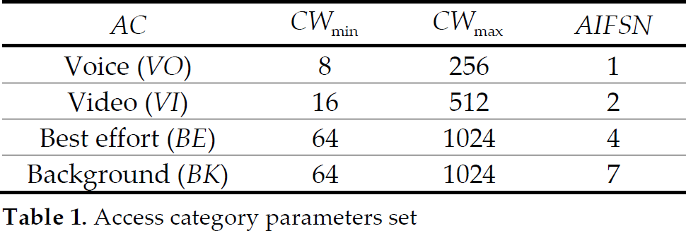
Each station (STA) chooses a random backoff interval between 0 and
Although AC provides differentiated services, it suffers from degraded performance depending on the traffic load [7, 8]. This is because each AC chooses backoff parameters statically, regardless of the traffic load. Thus, AC can underutilize the channel under a light traffic load, whereas excessive collisions can occur under a heavy traffic load. In particular, when using a directional antenna, CW should be applied to the number of stations and the type of application traffic in every sector. If a directional antenna is used, the communication space is supposed to be divided into several sectors according to the antenna element. This has the same effect of using an omni-antenna, though the directional antenna is actually used because it communicates with STAs of the sector as it rotates in a circular manner. In general, STA is not distributed uniformly in the space. Therefore, the number of STAs existing in each sector becomes different and the number of STAs used to communicate with the PNC also becomes different as a result. Though the number of STAs that exist in each sector is different, IEEE 802.15.3c allocates regular S-CAP (Sub Contention Access Period) to all sectors uniformly for the STAs to send commands to the PNC. Furthermore, initial
Therefore, we propose the dynamic allocation algorithm of
The remainder of the paper is organized as follows. In Section 2 we briefly survey related studies found in the literature. In Section 3 we introduce the IEEE 802.15.3 MAC protocol, and then we present an A3 considering directional antenna and dynamic
2. Related work
Currently, several standards have been or are being defined to achieve multi-gigabit rates for 60GHz wireless networks such as IEEE 802.15.3c [1] and ECMA-387 [2]. Both standards focus on using Time Division Multiple Access (TDMA) for data communications. Existing MAC protocols recently proposed for 60GHz networks [9, 10] are also based on TDMA. Because data traffic is bursty, the required medium time is often highly unpredictable. A TDMA-based MAC protocol may cause either high overhead for on-the-fly medium reservation or under- or over-allocated medium time for individual users. Furthermore, because scheduling is computationally intensive and should be executed in real time, it is challenging to implement such an AP on a mobile station.
Contention-based MAC protocols, such as the CSMA/CA mechanism, work well with bursty traffic and operate robustly in unlicensed bands [11]. However, the CSMA/CA mechanism does not work well with directional antennas due to impaired carrier sensing. Under the CSMA/CA mechanism, stations (STAs) that see a busy medium compete for access to the medium by waiting for a random number of slot times before the next attempt for transmission. Usually the STA with the smallest random number will gain access to the medium. The other STAs will detect the transmission through a carrier sense mechanism and defer their attempts for channel access until the medium becomes idle again.
As demand for WLAN services has grown dramatically recently, it has become a crucial issue to further improve the performance for CSMA/CA-based WLAN. In the literature, research has been directed toward three main areas. The first direction is from the MAC-protocol perspective [13-18]. The authors in [12] and [13] proposed a dynamic tuning algorithm to adjust the backoff window size according to the traffic load. In addition, a fast backoff procedure was proposed by Kwon et al. [14]. Packet-pipeline scheduling [15] and out of band signalling [16] were proposed to reduce the possibility of frame collision. In [17], a frame concatenation mechanism was introduced to reduce the protocol overhead. The second research direction to improve the throughput of CSMA/CA-based WLAN is to incorporate the capture effect [18]. With the capture effect, a user can transmit data, even with other simultaneously transmitting users.
3. System description
3.1. Overview of IEEE 802.15.3c MAC protocol
We consider a WPAN as illustrated in Figure 1. In such a network, one STA acts as a PNC that coordinates medium access for multiple other STAs. The PNC also provides basic timing for the network and manages membership of the network. STAs can communicate with the PNC or they can communicate with each other directly without having to bridge data through the PNC. The ND process is embedded in the association process between the STAs and the PNC, with any capable STAs being able to act as a PNC. The PNC collects the information on the piconet from the STAs. In the omni-mode, STAs in each direction send channel time requests and their locations to the PNC.

A WPAN network consisting of one PNC and five STAs
The PNC provides the basic timing for the piconet by using multidirectional round-robin transmission in order to allow STAs located in different directional coverage areas to join the piconet. The PNC is responsible for channel resource allocation and load control, which is implemented by maintaining an admission table that is directionally broadcasted periodically via the beacon frame.
The channel time in the piconet is based on the time slotted superframe, which consists of three major components, the beacon, the CAP and the channel time allocation period (CTAP). The superframe structure of IEEE 802.15.3c is presented in Figure 2.
The CAP may be divided into two sections, the association CAP and the regular CAP (R-CAP). The association CAP is only used by STAs to send association request commands to the PNC, whereas the R-CAP can be used for data exchanges between STAs (STA-to-STA communication) and reservation procedures between STAs and the PNC (STA-to-PNC communication). Because the network allocation vector is not used in IEEE 802.15.3c, the probability of collisions between STA-to-STA communications may be higher than for IEEE 802.11 distributed coordination function (DCF) owing to the hidden STAs. In addition, in STA-to-PNC communication, the PNC has to perform a scheduling when it receives a request command from an STA. Upon the completion of the scheduling, the PNC sends the response frame back to the STA. Therefore, it is impossible to send the response frame after a short interframe space (SIFS). The reservation in R-CAP is not for the time immediately after the negotiation, but for future channel time allocations in CTAP. Time division multiple access is employed in CTAP and the reservation is on a per-flow basis rather than a per-packet basis and maintained until the stream is torn down. In STA-to-STA communication in IEEE 802.11, however, if an STA receives a ready to send (RTS), it sends clear to send (CTS) back to the transmitter after an SIFS. After successful reception of the CTS, the transmitter sends data packets immediately after an SIFS. Because RTS/CTS cause overheads and they are only optional, nowadays they are usually disabled.

IEEE 802.15.3c superframe structure
In the CSMA/CA mechanism, each frame maintains two variables that are defined by the retry count and backoff window. Retry count is the number of backoff times caused due to unsuccessful transmission of a frame. A backoff window is the number of backoff slots that an STA must wait for before attempting to access the channel at the retry count. According to the standard, the retry count is an integer taking values between [0, 3] and the corresponding backoff window is [7, 15, 31, 63]. The backoff window (a) is denoted as
The association and channel time allocation procedures in IEEE 802.15.3c WPANs are as follows: once an STA is willing to join, a certain piconet listens to the beacon transmitted by the PNC, it sends the association request command frame to the PNC during the association CAP indicated in the received beacon. In response to the association request command frame, the PNC sends the association response command frame, allowing it to join the piconet. The PNC can notify the information on STAs available in the piconet by transmitting the beacon frame or the announcement frame with the STA association information element, including current member information.
3.2. Directional antenna model
As for a directional antenna used in mmWave WPANs, there are two candidates for the antenna model: the flat-top model neglecting the sidelobe of the radiation and the cone plus circle/sphere model considering the sidelobe of the radiation. When we assume that all STAs are located in a two dimensional space, the cone plus circle model is applied. Then, the antenna gain for mainlobe is defined by

Cone plus circle antenna model
Figure 3 shows the radiation pattern when the cone plus circle antenna model is employed.
Let

where is the wavelength of the signal given by
4. Adaptive allocation algorithm
4.1. Proposed adaptive allocation algorithm
The proposed A3 consists of two phases. The first phase allocates regular S-CAP dynamically according to the number of STAs that exist in each sector. The second phase allocates initial CW values considering the number of STAs against allocated regular S-CAP.
In the case of using a directional antenna in IEEE 802.15.3c, the PNC communicates per sector and can receive the table by checking the number of STAs that exist in each sector. The existing data transmission method is that the PNC allocates the same size of regular S-CAP to each sector STA, by which preoccupied channels get allocated CTA sections through the CSMA/CA mechanism and transmit data to other STAs. STAs which exist in the same sector have to compete with each other in the same size of allocated regular S-CAP to preoccupy channels for data transmission regardless of their number. Therefore, the probability of command conflict becomes relatively higher in the sector having a greater number of STAs. Furthermore, the probability of conflict becomes much higher because it is not easy to find out which STA is communicating with the PNC, even within the same sector in an environment when using a directional antenna. Therefore, in order to reduce the probability, it is necessary to allocate dynamic regular S-CAP according to the number of STAs which exist along each direction.
The PNC can recognize the number of STAs for each sector up to the previous superframe through its own information table. Utilizing the information, the PNC allocates the regular S-CAP area out of CAP in proportion to the number of STAs, as in (2).

where
Figure 4 illustrates the activity of the proposed algorithm of dynamic regular S-CAP allocation. Figure 5 indicates an example of co-existence of one PNC and 10 STAs in one piconet. At this time, the antenna elements of PNC are 8, which means to be 45 degree each sector.

Example of network topology
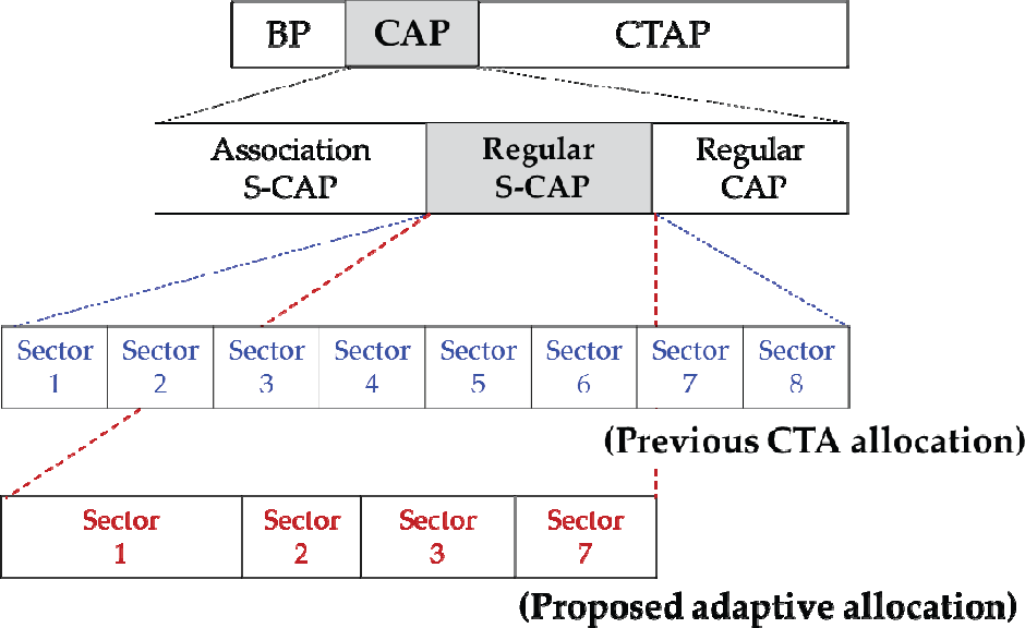
Illustration of previous CTA allocation and proposed adaptive allocation
There exists 4, 1, 2, 3 STAs in direction 1, 2, 3, 7 and no STAs exist in direction 4, 5, 6, 8. If the proposed algorithm is not applied in this circumstance, the area for sector 1~8 in regular S-CAP would exist as the same size altogether. On the other hand, if the proposed algorithm is applied, it can be recognized that regular S-CAP in CAP is allocated only for sectors 1, 2, 3, 7 in proportion to STAs and not allocated for sectors 4, 5, 6, 8 as in Figure 4. Such that if the proposed algorithm is used, system efficiency can be increased by reducing the probability of conflict between commands of STAs along more allocation of regular S-CAP to more sectors, as well as prevention of unnecessary allocation of regular S-CAP.
4.2. CW allocation
For STAs of the piconet to transmit data to other STAs, a command to obtain the CTA section has to be transmitted to the PNC first. While the procedure is implemented through CAP, the existing CSMA/CA mechanism allocates the same competing window initial value for each sector. In the case of a sector with a smaller number of STAs, system efficiency is reduced by an unnecessary back procedure. On the other hand, in the case of a sector with a greater number of STAs, the probability of conflict is increased in relation to the previous case. Therefore, an algorithm is proposed for controlling the competing window initial value considering the number of STAs which exist in each sector.
In order to decide optimal initial value of the competing window, the method of applying approximation of p out of p-persistent MAC to contention window size of CSMA/CA mechanism [22] is used. If the value of backoff counter is selected from [0, CW-1],

where
If value of
Furthermore, we consider the ACs. In the 4-bit AC field, the ath bit represents that the STA has frames of AC a, where the indexes of VO, VI, BE and BK ACs are 1, 2, 3, and 4, respectively.
Let

Adaptive allocation algorithm

To determine
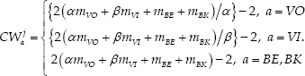
From Table 1, we have
After deciding the CW value, each STA follows the CSMA/CA mechanism to access the channel as in CTA. In the CSMA/CA mechanism, if a frame incurs a collision, the CW value is increased to
5. Performance evaluation
In this section we first describe the simulation environment and then present simulation results in terms of the average latency and the throughput.
5.1. Simulation environment
To define channel access parameters, VO and VI ACs have the packet sizes of 168 bytes and 1,064 bytes including the RTP/UDP/IP headers, respectively. On the other hand, the packet size in BE and BK ACs is 1,540 bytes with TCP/IP headers. All the traffic sources are randomly activated and the packet arrival process is drawn from a Poisson distribution with rate
In addition, we use a video trace file to simulate a more realistic environment, as shown in Figure 6. The sample trace file is “Terminator 2”, which is encoded by the H.264/MPEG-4 AVC High codec with the frame size of HD 1280 by 720 pixels. This trace file is half an hour long with a GoP structure (12, 2), where GoP structure (N, M) denotes that there are N frames in the GoP and the M parameter represents the maximal count B frames between two anchor frames (I or P). For instance, a GoP of (12, 2) stands for IBBPBBPBBP.
Moreover, the maximum video frame size is 405,006 bytes and the average frame size is 119,212.403 bytes possessing high burstiness, as shown in Figure 5. The concrete properties of H.264 video trace library are listed in Table 4.
Simulation parameters

Video traffic file statistics


Video frame size vs. frame sequence number (Terminator 2 sample HD video trace file)
5.2. Simulation results
From Figure 7 it can be seen that the latency increases as the number of STAs present increases because STAs experience more channel collisions. In the proposed adaptive allocation algorithm, each STA can adjust its CW value depending on the traffic load and therefore the latency can be markedly reduced when a large number of STAs are present. Specifically, the adaptive allocation algorithm can reduce the latency by 67% for VO, 66% for VI, 62% for BE and 61% for BK when compared with CTA. Because the throughput is inversely proportional to the latency, the adaptive allocation algorithm can improve the throughput for each AC, as will be discussed.

Average latency as the number of stations

Average throughput as per the number of stations
Moreover, the adaptive allocation algorithm preserves the relative priority among ACs. For example, when the number of STAs is 20, the average latencies of CTA in VO, VI, BE and BK ACs are 3.84, 22.16, 33.05 and 33.78 ms, respectively. That is, the relative latency ratios among ACs are 1:5.77:8.6:8.79.
On the other hand, the adaptive allocation algorithm average latencies in VO, VI, BE and BK ACs are 1.32, 7.68, 11.44 and 11.7 ms, respectively, and the ratios are 1:5.81:8.66:8.86. Consequently, we have demonstrated that the adaptive allocation algorithm can guarantee a comparable level of service differentiation to CTA.
In particular, Figure 7 shows the latency between the adaptive allocation algorithm and CTA when a real video trace file is used for simulations. When a HD trace with VBR characteristics is applied, CTA shows a sharp increase in the average latency as the number of STAs increases. In contrast, the adaptive allocation algorithm shows a relatively slow and stable increase in the average latency.
Figure 8 shows the throughput when the same simulation parameter is used. As the number of STAs increases, the difference in throughput between the two protocols also gradually increases. In short, when the traffic load is high, the adaptive allocation algorithm outperforms CTA because the adaptive allocation algorithm can adjust backoff parameters depending on the traffic load.
6. Conclusion
In this paper we proposed the use of the optimal contention window size and transmission probability by taking into consideration the number of stations and access categories in mmWave WPANs. The proposed algorithm allocates regular S-CAP within CAP backoff competing window initial value dynamically based on the information after checking the existing number of STAs for each sector by the PNC. Extensive simulation results demonstrate that the proposed algorithm can reduce the average latency and improve the throughput significantly when the number of contending stations is high. Consequently, the proposed algorithm can be widely used to enhance the performance of 60GHz stations in mmWave WPANs.
Footnotes
7. Acknowledgments
This research was supported by the KCC (Korea Communications Commission), Korea, under the R&D programme supervised by the KCA (Korea Communications Agency) (KCA-2011-08913-04002).