
Abstract
This paper presents a novel method to achieve stereoscopic vision for mobile robot (MR) navigation with the advantage of not needing camera calibration for depth (distance) estimation measurements. It uses the concept of the adaptive candidate matching window for stereoscopic correspondence for block matching, resulting in improvements in efficiency and accuracy. An average of 40% of time reduction in the calculation process is obtained. All the algorithms for navigation, including the stereoscopic vision module, were implemented using an original computer architecture for the Virtex 5 FPGA, where a distributed multicore processor system was embedded and coordinated using the Message Passing Interface.
Keywords
1. Introduction
Navigation in the mobile robotics ambit is a methodology that allows guiding a mobile robot (MR) to accomplish a mission through an environment with obstacles in an efficient and safe way, and it is one of the most challenging competences required of any MR. The success of this task requires a proper coordination of the four main blocks involved in navigation: perception, localization, cognition and motion control. The perception block allows the MR to acquire knowledge about its environment using sensors. The localization block must determine the position of the MR in the environment. Using the cognition block the robot will select a strategy for achieving its goals. The motion control block contains the kinematic controller, its objective is to follow a trajectory described by its position [1]. The MR should possess an architecture able to coordinate the on-board navigation elements in order to achieve correctly the different objectives specified in the mission with efficiency either in indoor or outdoor environments.
In general, global planning methods complemented with local methods are used for indoor missions since the environments are known or partially known; whereas, for outdoor missions, local planning methods are more suitable.
In previous work, we developed a path planning method for wheeled MR navigation using a novel proposal of ant colony optimization named SACOdm (Simple Ant Colony Optimization with distance (d) optimization and memory (m) capability) to consider obstacle avoidance in a dynamic environment [2]. In order to evaluate the algorithm, we used virtual obstacle generation, being indispensable in real-world applications as a way of sensing the environment.
There are several kinds of sensors, broadly speaking they can be classified as passive and active sensors. Passive sensors measure the environmental energy that the sensor receives, in this classification some examples are microphones, tactile sensors and vision-based sensors. Active sensors emit energy into the environment with the purpose of measuring the environmental reaction. It is common that an MR has several passive and/or active sensors; in our MR, for example, the gear motors use optical quadrature encoders, it uses a high precision GPS for localization and two video cameras to implement a stereoscopic vision system for object recognition and localization of obstacles for map building and map reconstruction.
This work presents a proposal to achieve stereoscopic vision for MR application,
its development and implementation into FPGA technology to obtain high performance computation to improve local and global planning, obtaining a faster navigation by reducing idle times due to slow computations. This is done by taking advantage of the Virtex 5 XC5VFX70 capacities to integrate a distributed multicore system with a hard-processor PowerPC 440 as the master and five Microblaze 32-bit soft-processor slaves. With this approach, a complete soft-core processor and its local memory is dedicated to handle every navigation block, therefore, perception, localization, cognition and motion control are handled by four soft-processors; the fifth processor is devoted to achieving local planning. The PowerPC440, using the Message Passing Interface (MPI) communication method handled by the Intellectual Property Core (IP) named “mailbox”, coordinates the five slaves. The system can communicate with the global planner; the entire system is running under the XilKernel, which is a Kernel of Xilinx.
The global planner uses ant colony optimization to obtain the real-time optimal routes [2], therefore, it can work in a dynamic environment where obstacles are not fixed at specific positions. In the global planner, every ant is a virtual mobile robot (MR). The complete system is composed by the MR and the global planner in the main computer, see Fig 1. The system has the task of constructing the map based on a representation of the environment scene, avoiding the use of landmarks to make the system more versatile. The MR stereo vision transforms the visual information of two 2D images of the same scene environment into deep measure data. Hence, the MR sends this data via RF to the global planner in the main computer; this data is a 3D representation of the MR's scene environment and its local position and orientation. In this way, the optimal path in the environment is constantly updated by the global planner.
The MR stereo vision has an advantage with respect to other navigation techniques that depth can be inferred with no prior knowledge of the observed scene, in particular, the scene may contain not only motionless background elements, but also unknown moving objects.
To create and reconfigure the environment map, the MR makes an inference of the three-dimensional structure of a scene from its two dimensional 2D projections. The 3D description of the scene is obtained from different viewpoints. With this 3D description, we are able to recreate the environment map for use in robot navigation.
In general, in any stereoscopic vision system after the initial camera calibration, correspondence is found among a set of points in the multiple images by using a feature-based approach. Disparity computation for the matched points is then performed. Establishing correspondences between point locations in images acquired from multiple views (matching) is one of the key tasks in scene reconstruction based on stereoscopic image analysis. This feature-based approach involves detecting the feature points and tracking their positions in multiple views of the scene. In [3] is presented a review of the problem in which they discussed the developments in establishing stereoscopic correspondence for the extraction of the 3D structure. A few well-known algorithms representing widely different approaches were presented; the focus of the review was stereoscopic matching. An important issue is that map construction or reconfiguration of the MR environment does not necessarily need reconstruct of the exact scene of the environment.
There are other works along the same lines, in [4] an approach that integrates appearance models and stereoscopic vision for efficient people tracking in domestic environments is presented. In [5] the author used a vision system for obstacle detection and avoidance, a method was proposed to integrate the behaviour decisions by using potential field theory [6] with fuzzy logic variables. Hue, Saturation and Intensity (HSI) colour were used since it is perceptually uniform. In [7] an omnidirectional vision camera system that produces a spherical field of view of an environment was presented, the continuation of this work was presented in [8] where the authors explained several important issues to consider for using a fisheye lens in omnidirectional vision, some of them are lens camera calibration, rectification of the lens distortion, the use of a particle filter for tracking as well as the algorithms and the hardware configuration implemented.
Recently, the company Mobile Robots announced a heavy-duty high speed stereoscopic vision system for robots called the “Mobile Ranger Stereo Vision System,” that can provide processed images at a maximal rate of 60 fps (frames per second) with a resolution of 752 × 480 pixels.
The proposed method has some advantages over existing methods; briefly, we can say that the whole system is integrated into a single FPGA device, where a master hard-processor is coordinating five slave soft-processors, the system is running under an efficient operating system; the programs were developed in C language; the system does not need camera calibration for depth (distance) estimation measurements; an improved efficiency in the stereoscopic correspondence for block matching; adaptive candidate matching window concept is introduced for stereoscopic correspondence for block matching, resulting in improved efficiency by reducing calculation time; also, improved matching accuracy assuring corresponding process only in the areas where there are vertical or corners arranged pixels, corresponding to the obstacles selected features. The calculation process is reduced on average by 40% corresponding to the surface ground image content which was previously extracted from every image. The areas between edges in the obstacles itself are also excluded from the matching process, this is an additional increase in the method efficiency by reducing calculation for the matching process.
Recent works that address this same topic with a different approach are: in [9] a method to acquire range information for mobile robots, a DSP-based range finding system with binocular stereo vision is proposed. In [10] the authors propose a new calibration scheme based on calibration equations that introduce fewer approximation errors to reduce kinematic modelling errors introduced by odometry. In [11] a comparative study of bio-inspired algorithms applied to optimize type-1 and type-2 fuzzy controllers for autonomous mobile robots is presented. Since the use of FPGAs is gaining ground in this kind of application, in [12] the design of an embedded type-2 fuzzy controller into an FPGA is described, while in [13, 14] particularities of the design and simulation procedure are explained.
This work is organized as follows: in Section 2 the general system architecture
is explained. Section 3 is dedicated to giving a description of the process to extract the surface ground and obstacle edge detection using luminance components, as well as the process when we include the hue to obtain the ground surface; moreover, in this section, we comment on some advantages obtained from the implementation of the vision module into an FPGA. In Section 4 some important concepts about stereoscopic vision are given. In Section 5 we explain how the modification of the road map is achieved.
Finally, in Section 6 the conclusions are given.
2. General System Overview
Fig. 1 shows the two main components of the system architecture; the computer and the MR:

The global planner is in the computer communicated through RF with the MR, this is shown in 1). In 2) is the MR with its main components: a) the cameras, b) FPGA system board, c) H-bridge motor driver, d) RF communication system based on Zigbee technology, e) Magnetic Compass, f) GPS module, g) Gear Pittman DC-motors, h) NTSC Composite video to RGB converter cards.
The computer contains the global planner based on the SACOdm algorithm and the communication system.
The MR is a three wheeled system with frontal differential tracking. The on-board computer is based on a Virtex 5 FPGA, it has a hard-processor PowerPC 440 that coordinates five slave Microblaze soft-processors and it communicates with the Peripheral module. In Fig. 1 the main subsystems can be identified:
the stereoscopic vision includes parallel arrange dedicated purpose video decoders,
the Virtex 5 FPGA controller board that contains the six embedded processors, as well as the motors and tracking controllers that were coded in ANSI C,
the power module consists of a high-capacity group of rechargeable batteries (not shown in the figure), two H-bridges motor drivers and the two Pittman DC geared-motor model GM9236S025-R1,
the communication system is based on the XbeePro RF, the integrated WiFi communication module,
a high-accuracy GPS based on the OEMV-2 receiver model GPS6185HR that provides a resolution of 1 cm of resolution [15],
an electromagnetic custom made compass IIC bus compatible based on the LSM303DLH integrated circuit from ST-Microelectronics.
The communication between the MR and the computer is achieved using the XBeePro RF modules that meet the IEEE 802.15.4 standards; the modules operate within the ISM (Industrial Scientific and Medical) 2.4 GHz frequency band. The range of application for indoor/urban range is 100 metres (m) and for outdoor applications with RF line of sight the range is about 1500 m. The serial data rate is between 1.2 kbs (kilo bits per second) and 250 kbs [16]. With no hardware modification it is possible to change the RF module to the XBee-Pro XSC to improve the communication range from 370 m for indoor/urban applications and 9.6 Km for outdoor line sight applications.
In Fig. 2 a more detailed description of the stereoscopic vision system is given; each video camera is connected to a conversion board from NTSC composite video to RGB 24 bits video signals, which in turn are controlled by the FPGA-based controller board using IIC communication. The video cards send the video information to the controller board where it is processed.

Detailed overview of subsystems of the stereoscopic vision stage on-board f the MR.
Fig. 3 shows the multicore processor system implemented into the Virtex 5 FPGA. This multicore system works as a distributed computer system where the PowerPC 440 is the system's master and the Microblaze processors are the slaves. Each slave is a 32 bit soft-core processor with Harvard's architecture embedded into the Virtex 5 FPGA. The Microblaze allows customizing its architecture for a specific application. It can manage 4 GB of memory. The 32 bits Local Memory Bus (LMB) connects the processor's core to the RAM Memory Blocks (BRAM) for data (DLMB) and instruction (ILMB) handling. It uses the Processor Local Bus (PLB), also called On-Chip Peripheral Bus (OPB), to connect different slave peripherals (SPLB) with the CPU, for data and instruction exchange it uses the DPLB and IPLB, respectively; moreover, it contains the Microprocessor Debug Module (MDM) giving the possibility of achieving real-time debugging using the JTAG interface. In the figure, the peripherals PWM, RS232, IIC, timers, etc., are connected to the PowerPC 440. These last modules were designed for specific application and glued to the distributed architecture. All the applications were programmed using ANSI C/C++ language.

Multicore system implemented into the FPGA Virtex 5 XC5VFX70.
3. Description of the Detection Module with Stereoscopic Vision
The navigation task is achieved using the relative depth representation of the obstacles based on stereoscopic vision and epipolar geometry. The map represents the status at the time of drawing the map, not necessarily consistent with the actual status of the environment at the time of using the map. Mapping is a problem of integrating the information gathered in this case by the MR sensors into a complex model and depicting with a given representation. Stereo images obtained from the environment are supplied to the MR, by applying the disparity algorithm on stereo image pairs, a depth map for the current view is obtained. A cognitive map of the environment is updated gradually with the depth information extracted while the MR is exploring the environment. The MR explores its environment using the current views, if an obstacle in its path is observed, the information about the target obstacles in the path will be sent to the global planner in the main computer. After each movement of the MR in the environment, stereo images are obtained and processed in order to extract depth information. For this purpose, an obstacle's feature points (obstacle edges) are extracted from the images. Corresponding pairs are found by matching the edge points, i.e., pixel's features which have similar vertical orientation. After performing the stereo epipolar geometry calculation, depth for the current view is extracted. By knowing the camera parameters, location and orientation, the map can be updated with the current depth information.
3.1. Surface Ground and Obstacle Detection Using Luminance and Hue
The vision-based obstacle detection module classifies each individual image pixel as belonging either to an obstacle or the ground. The appearance-based method is used for surface ground classification and extraction from the MR vision module captured images, see Fig. 4. Any pixel that differs in appearance from the ground is classified as an obstacle. After surface ground extraction, the remaining image content is only obstacles. A combination of pixel appearance and feature-based methods is used for individual obstacle detection and edge extraction. Obstacle edges are more suitable for stereo correspondence block matching in order to determine the disparity between left and right images. For ground surface extraction purposes two assumptions were established that are reasonable for a variety of indoor and outdoor environments:

Process in the detection module for surface ground extraction and obstacle edge detection using the luminance component.
The ground is relatively flat.
Obstacles differ in colour and appearance from the ground. This difference is reasonable and can be subjectively measured as Just Noticeably Difference (JND), which is reasonable for a real environment.
The above assumptions allow us to distinguish obstacles from the ground and to estimate the distances between detected obstacles using the vision-based system. The classification of a pixel as representing an obstacle or the surface ground can be based on local visual attributes: intensity, hue, edges and corners. Selected attributes must provide information so that the system performs reliably in a variety of environments. Selected attributes should also require low computation time so that real-time system performance can be achieved. The less computationally expensive the attribute, the higher the obstacle detection update rate; consequently the MR can travel safely and speedily.
For appearance classification we used hue as a primary attribute for ground surface detection and extraction, see Fig. 5. Hue provides more stable information than colour or luminance based in the pixel grey level. Colour saturation and luminance perceived from an object is affected by changes in incident and reflected lightness. Furthermore, compared to texture, hue is a more local attribute and faster to calculate. In general, hue is one of the main properties of a colour, defined as the degree of perceived stimulus described as red, green, blue. When a pixel is classified as an obstacle, its distance from the MR stereo vision camera system is estimated.

Process in the detection module for surface ground extraction using hue and obstacle edge detection using luminance components.
The considerations for the surface ground extraction and obstacle edge detection for correspondence block matching are:
Colour image from each video camera is converted from NTSC composite video to RGB 24 bits colour space.
A typical ground area in front of the MR is used as a reference. The hue attributes from the pixels inside this area are histogrammed in order to determine its hue attribute statistics.
Surface ground is extracted from the scene captured by the MR stereo vision by means of a comparison against the reference from point 2 above, and based on the hue attribute. Hue limits are based in JND units.
The remaining contents in images are only obstacles. Edges are extracted from individual obstacles based on feature and appearance pixel attributes.
Correspondence for block matching is established in pixels from the obstacle vertical edges.
The disparity map is obtained using the sum of absolute differences (SAD) correlation method.
3.2. Vision System Module FPGA Implementation
When a robot has to react immediately to real-world events detected by a vision system, high speed processing is required. Vision is part of the MR control loop during navigation. The sensors and the processing system should ideally respond within one robot control cycle in order not to limit their MR dynamic. An MR vision system requires high computational power and data throughput which means computation time often exceeds the abilities to properly react. The vision system consists of a stereoscopic vision module implemented in C language in the FPGA. Video information is processed in a stereo vision system and video interface. The NTSC composite video signals from each camera, after proper low pass filtering and level conditioning, is converted to RGB 24 bits colour. The vision module has two dedicated Microblaze soft-processors, one of them for achieving image matching computations that are computationally expensive. This module interacts through the system master with the local and global planners. In the ant colony-based global planner, every ant is a virtual fully equipped MR trying to find the optimal route, eventually, if it exists, it will be obtained. Of course, the ACO-based planner will give the best route found and the real ant, the MR, which is equipped on-board with the vision system, will update the global map in the planner.
4. Design of the Stereoscopic Vision Module
The two stereo cameras are parallel aligned and capture images of the same obstacle from different positions. The 2D images on the plane of projection represent the object from the camera view. These two images contain the encrypted depth distance information. This depth distance information can be used for a 3D representation in the ant colony environment in order to build a map.
4.1. Stereoscopic Vision
The MR using its side by side left and right cameras sees the scene environment from different positions in a similar way to human eyes, see Fig. 6. The FPGA-based processing system finds corresponding points in the two images and compares them in a correspondence matching process (CMP). Images are compared by shifting a small pixel block “window”. The result is a comparison of the two images together over the top of each other to find the pixels of the obstacle that best match. The shifted amount between the same pixel in the two images is called disparity, which is related to the obstacle depth distance. Higher disparity means that the obstacle containing that pixel is closer to the cameras. The least disparity means the object is far from the cameras, if the object is very far away, the disparity is zero, that means the object on the left image is at the same pixel location as on the right image.
Projection of one point into left and right images from parallel stereo cameras.
Fig. 10 shows the geometrical basis for stereoscopic vision by using two identical cameras which are fixed on the same plane and turned in the same direction, parallax sight. The position of the cameras is different in the X axis. The image planes are presented in front of the cameras to model the projection more easily. Consider point P on the object, whose perspective projections on the image planes are located at PL and PR from left and right cameras respectively. These perspective projections are constructed by drawing straight lines from the point to the centre lens of the left and right cameras. The intersection of the line and image plane is the projection point. The left camera's projection point PL is shifted from the centre, while the right camera's projection point PR is at the centre. This shift of the corresponding point on left and right camera can be computed to get the depth information of the obstacle.
4.2. Depth Measure from Stereo Image
In order to calculate the depth measure of the obstacles in the scene, the first step is to determine the points of interest for correspondence matching between the two images. These corresponding points are selected based on the obstacle edge feature. Then the depth distance is calculated based on the shifting “disparity”. The disparity is calculated based on the amount of pixels shifting in a particular corresponding point. There are stereo image constraints assumed for solving the correspondence problem:
Uniqueness. Each point has at most one match in the other image.
Similarity. Each intensity colour area matches a similar intensity colour area in the other image.
Ordering. The order of points in two images is usually the same.
Continuity. Disparity changes vary slowly across a surface, except at depth edges.
Epipolar constraint. Given a point in the image, the matching point in the other image must lie along a single line.
4.2.1. Photometric Correspondence by Block Matching
The map for representation of the ant colony environment is estimated based on the geometrical relationship between the world points and their projections on the 2D images captured by the MR stereo visual system. An obstacle's deep measure is calculated by epipolar geometry. The central problem in doing this is estimating corresponding points in one image with respect to the other image [17]. This stereo correspondence problem is usually solved by assuming that the cameras are fixed and their relative positions are known [18]. The stereo images have to be rectified in order to align the epipolar lines to the optical centres' joining line of the stereo cameras before solving the correspondence problem [19]. In order to avoid image rectification and to simplify camera calibration and stereo CMP, the stereo cameras are arranged in a parallel configuration [20]. The correspondence problem concerns the matching of pixels in two images such that the matched points are the projections of the same point on the same horizontal line in the scene. The stereo corresponding searching process is confined to one dimension along the horizontal axis; stereo matching is used to generate the disparity or depth maps of the ant colony environment. Generally, depth information is obtained from two broad categories of stereo matching algorithms [21] – global and local. Global based algorithms, for example those described in [22], produce accurate disparity maps, but involve high computational costs; on the other hand, local algorithms [23,24] are computationally efficient, but do not produce results as accurately as global algorithms. We used a local or area-based window correlation matching algorithm due to their computational efficiency as compared to global algorithms, see Fig. 7. The construction of stereo images allows for a disparity in only the horizontal direction, there is no disparity in the Y image coordinates. This is a property that can also be achieved by precise alignment of the stereo cameras by means of epipolar geometry, see Fig. 6.

Reference and searching windows in the stereo correspondence by the block matching process using SAD.
The disparity is usually computed as a shift to the left of an image feature when it is viewed in the right image, it is calculated by determining a measure of the Sum of the Absolute Differences (SAD), that is used to calculate disparities at each pixel in the right image, see Fig. 7. For every point of interest captured in the environment scene, a matching reference window is defined by 8 × 8 pixels and a searching area of 80 × 80 pixels around the matching reference window. The reference window from the left image is matched into a corresponding same size window in the right image. This 8 × 8 reference window from the left image is shifted over the searching area of 80 × 80 pixels in the right image. At every shift, the absolute difference of comparing pixel attributes is computed and saved. After this SAD “match strength” has been computed for all valid disparities, the disparity that yields the lowest SAD is determined to be the disparity at that location in the right image.

where (x;y;d) is the value for the disparity at point L(x;y) of the left image and the corresponding point R(x + d; y) of the right image. L(x; y) and R(x; y) are the pixel attribute at left and right image respectively. The disparity at a certain point is the value of d that minimizes SAD.
The computational time can be minimized by reducing the number of valid disparity searches at every shift, limiting the disparity to a maximum value, where d is the disparity based on a maximum value for disparity dmax. Another way to reduce computational time is by reducing the searching area. The size of the optimal pixel searching area can be estimated based on the image noise, quality of pixel attributes, edge detection and estimated disparity at points of interest in the scene.
4.2.2. Constraints for Matching
Because of factors such as noise and occlusions, the appearances of the corresponding points will differ in the two images. For a particular feature in one image, there are usually several matching candidates in the other image. It is convenient to use additional constraints in order to obtain the correct match, commonly used constraints are:
The matching points must lie on the corresponding epipolar lines of the two images.
Each point has, at most, one match in the other image.
Each similarity intensity or colour area matches a similar intensity or colour area in the other image.
The disparity gradient should be within a certain limit. Due to occlusions in certain 3D surfaces, the appearances of the corresponding points will differ in the two images.
4.2.3. Novel Proposal to Improve the Efficiency in the CMP
The complexity may increase the CMP in those cases where the images are captured by a stereo vision system on-board a mobile robot (MR). The epipolar lines may vary from the horizontal axis because of vibrations due to variations in ground surface or by mechanical gears. In order to compensate for this condition, the epipolar lines and selected matching points may provide some indication during the matching process concerning the spatial position of the stereo cameras.
In our application, the epipolar lines are selected for robustness and efficiency by processing for matching only the image information represented by the edges of obstacles:
Stereo correspondence matching is done only in the portions of the images where there are obstacles. The extracted portion from the ground surface will be omitted from the matching process; this reduces the calculation time. In every captured image, on average at least 40% of the image content is composed of ground surface.
The points of interest used as candidates for matching are limited only to the vertical edges. After edge detection in both images, the remaining image data corresponds only to the obstacle's edge intensity information.
Adaptive Candidate Matching Window (ACMW). In order to detect the candidate points for matching and ensure these points belong only to the vertical edges, a candidate matching window 4 × 4 all zeroes (0's) is defined. This non-overlapping window is shifted horizontally in the left image, which is the reference image, see Fig. 8. At every shift, this window is logical compared, using the OR operator, with the information in the image in that position. If the result contains at least one vertical line containing logical ones (1's), then a matching reference window is selected, this is the matching window containing the image information in that location and it will be compared with the right image for the SAD matching process as described previously in the process of photometric correspondence for block matching. The 4 × 4 candidate matching window assures the SAD matching processing only in the image containing the obstacle's vertical edges. By doing this, all image portions previously filled with logical 0's will be excluded from the CMP. These 0's filled image areas are the surface ground and obstacle portions inside its edges. The SAD matching process computationally is more expensive than simple logical OR operations. Matching accuracy and calculation time optimization are the major advantages when using this system due to the novel concept of the candidate matching window.
Adaptive Window for Candidate Matching (AWCM). It can be implemented in the case of denser environments and wider diversity in the shapes of the target obstacles. More features of interest can be added like sharp corners, round corners, horizontal lines, etc. The method can be easily modified to combine vertical edges and corners. Fig. 9 shows an example of the process for Candidate Matching using corners as a feature of interest. It shows four outputs for right bottom corner; we can have 16 possibilities at the output in order to cover the four corner shapes.

Candidate matching window process using edges.

Candidate matching window process using corners.

Points PL and PR are the perspective projections of P in left and right views.
A feature-based correspondence matching method based on the obstacle's detected edges was used. As a metric to estimate the disparity the calculation is based on SAD. Some additional considerations to improve efficiency and robustness, such as CMW and ACMW, were applied.
4.2.4. Epipolar Geometry
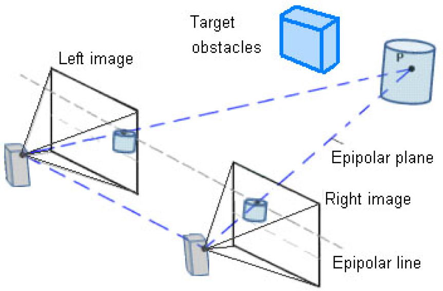
The epipolar geometry of the stereoscopic system is described in Fig. 10. The stereoscopic system model shows two different perspective views of a point in the obstacle (P) from two identical camera centres, which are separated only in X axis by a baseline distance. The points PL and PR in the image plane are the perspective projections of P in the left and right view. The plane passing through the camera centres and the object point in the scene is called the epipolar plane. The intersection of the epipolar plane with the image plane is called the epipolar line; the correspondences at point PL and PR must lie on the epipolar line.
The epipolar geometry is determined by the point correspondences. Selection and matching of the point features in the two views are the standard procedure for the depth recovery. The depth information can be evaluated using the triangle similarity algorithms. The epipolar geometry is illustrated in Fig. 11. In the illustration, the baseline distance (T) and the focus length (f) of both cameras are known. The perspective projection PL and PR on the epipolar line are shifted from their centre by distance XL and XR respectively.

A triangle formed by one point in 3D space and its projections.
4.2.5. Triangulation
One point in the 3D space and its projections in two images always compose a triangle; the reconstruction problem is to estimate the position of a point in 3D space. The 3D position (X; Y;Z) of a point P can be reconstructed from the perspective projection of P on the image planes of the cameras once the relative position and orientation of the two cameras are known. We chose the 3D world reference system to be the left camera reference system. For non-parallel stereo cameras, the right camera is translated and rotated with respect to the left one, therefore, six parameters describe this transformation. The simplest case arises when the optical axes of two cameras are parallel and the translation of the right camera is only along the X axis.
From Fig. 11 using the two triangles from left camera and right camera we can obtain the proportions, and considering the left camera as the reference, we can obtain

Then using those two proportions to solve for Z,

where, disparity is d = XL – XB. The disparity pixel coordinates (XL, YL) is for the image left frame; the baseline between the stereo cameras systems is T, and the Focal length is f,

The reference system for the left camera reference system according to a 3D point P = (X;Y;Z) is mapped by central projection into PL = (X;L;YL)

and into PR = (XR; YR); so, there is a translation in X axis due to baseline T

In the case of an origin at a mid-point between camera centres (cyclopean coordinates), for our one camera model, the new reference system is translated between both camera centres,

From the epipolar geometry, the projection point can be computed for each view and image points matched, then it can be back projected to give a 3D structure.
4.2.6. Stereo Image Model: Coordinate Systems and Scaling
Assuming that the cameras can be modelled by pinhole cameras, this model is shown in Fig. 12 upper left side. The 2D image considers four coordinate systems:

Coordinates system using the one camera model simplification. Z axis aligned with the XR MR local frame.
The (Xw; Yw; Zw) 3D coordinate system of the object point Q in the 3D world coordinate system.
The (X;Y;Z) 3D coordinate of the object point P in the 3D camera coordinate system, where the Z axis coincides with the optical axis.
The (x; y) imaging coordinate system with the original point (0; 0) with respect to the 3D coordinate system.
The (u; v) coordinate systems used in the computer or in the respective digital image.
Hence, according to the coordinate systems a relation exists between the different axes:

Considering ku, kv the image scale factors

By coordinate translation the scaled image coordinates (x; y) are transformed into the respective computer coordinate:

In this case (uo; vo) coincides with the image centre O. From the above equation
we obtain:

from the above equations,

In our case, the parameters uo, vo, ku, kv, f are the camera intrinsic parameters. Lens distortion coefficients are not considered in such a consideration [25].
4.2.7. Representing Robot Position
In order to specify the position of the robot on the plane, we establish a relationship between the global reference frame of the plane and the local reference frame of the robot, as in Fig. 12. The axes Xw and Yw define an arbitrary inertial basis on the plane as the global reference frame from some origin O: Xm; Yw. Normally, to specify the position of the robot, a point Q on the robot chassis is selected as its position reference point. The basis XB; YB defines two axes relative to Q on the robot chassis and is thus the robot's local reference frame. The position of Q in the global reference frame is specified by coordinates x and y, and the angular difference between the global and local reference frames is given by θ.
In our case, point Q is located at the middle of the baseline T between both camera centres, as it was determined in (7).
We can describe the pose of the robot as a vector with these three elements. Note the use of the subscript w to clarify the basis of this pose as the global reference frame:

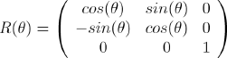
To describe robot motion in terms of component motions, it will be necessary to map motion along the axes of the global reference frame to motion along the axes of the robot's local reference frame. Of course, the mapping is a function of the current pose of the robot. This mapping is accomplished using the orthogonal rotation matrix:
5. Modifying Road Maps
Modification of the road maps is achieved using the information of disparity in pixels, where the distance of the MR from the obstacle is estimated using disparity measures – the smallest disparity measure means that the obstacle is far from the visual system of the MR. Moreover, the MR uses a high accuracy GPS and a digital compass for better navigation and orientation in the environment, and by means of epipolar geometry and disparity map calculation it can calculate the obstacle deep measure. The actual position and orientation has 1 cm of accuracy, which can be improved using odometry since the gear DC motors have optical encoders.
The information coming from the MR has all the necessary (x; y; d) coordinates and corresponding disparities, that in reality are a 3D representation of the 2D obstacle images captured from the stereoscopic visual system, see Fig. 13. After pixel scaling and coordinate translation, the global planner is able to update the environment. The perceived obstacles are sent to the global planner, which includes the visual shape and geographical coordinates. Once the global planner in the main computer has been modified using the new information about new obstacles and the current position of the MR, the global planner performs calculations using ACO to obtain an updated optimized path which is sent to the MR to achieve the navigation. The MR has the ability to send new information every 100 ms via RF from every scene captured; however, times in the global planner are bigger since it is based on a natural optimization method and it depends on the actual position of MR with respect to the goal. Hence, most of the time a new global optimal path can be obtained every 3 seconds.
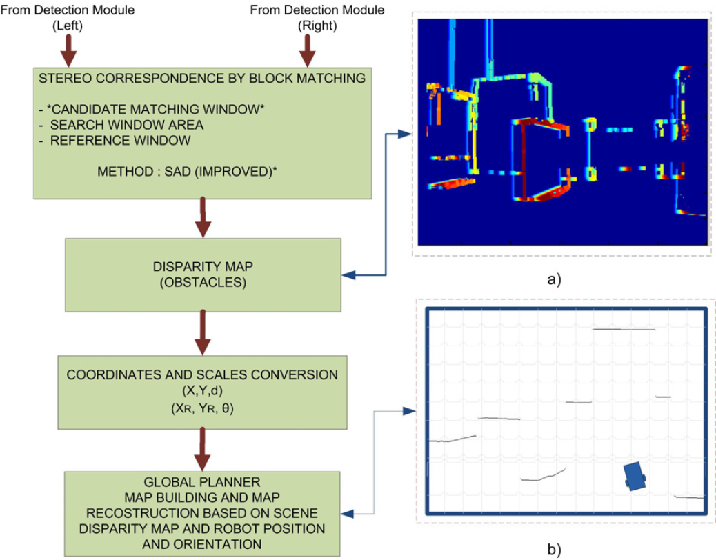
Process for map building and map reconfiguration.
6. Conclusion
In this work we presented the design of a stereoscopic vision module for a wheeled MR suitable for implementation into FPGA technology to obtain high performance computation in the whole system. We used the Virtex 5 XC5VFX70 FPGA to integrate a multicore distributed system where the hard-processor PowerPC 440 is the master and five Microblaze soft-processors are the slaves. The master uses MPI to communicate with the slave processors that are in charge of the different tasks required by the MR; the communication of the master with slaves is achieved through IP Mail, which is a soft-core that allows communication using MPI. The system uses the Kernel of Xilinx “XilKernel”.
The stereoscopic vision system captures left and right images from the same MR scene, the system is capable of using both appearance-based pixel descriptors for surface ground extraction and luminance or hue depending on the environment's particular characteristics. In an environment with constant lightness, minimum reflections and proper setting at the edge detector threshold level, luminance can be suitable because surface ground and obstacle edge detection can be performed at the same time. For an environment with variable or uncertain light conditions, hue is the primary attribute as a pixel appearance descriptor in the surface ground extraction process due to its invariance to changes in luminance and colour saturation. After surface ground extraction and obstacle edge detection, stereoscopic corresponding by block matching is performed, the correspondence is found among a set of points in the left and right images using a feature-based approach. Disparity computation for the matched points is then performed. Establishing correspondences between point locations in images acquired from multiple views (matching) is one of the key tasks in the reconstruction based on stereo image analysis. This feature-based approach involves detecting the feature points and tracking their positions in multiple views of the environment. Stereoscopic camera calibration is not required due to the improvements in the matching process. Disparity maps, which are the depth measure of the obstacle's position in the environment, are obtained after the stereo correspondence process. The MR sends this data, including its position and orientation, via RF to the global planner located in the main computer outside the environment. With this information, the global planner is able to constantly update the environment map.