
Abstract
Recently we have proposed a low cost solar concentrator based on a large number of small flat mirrors that approximates parabolic surface needed for solar light concentration. In this work we describe an improvement of the concentrator support frame assembly. The improvement is connected with the design of the gauge/guages for support frame adjustment. The gauge has the parabolic edge and rotates in the central tube. Special nuts are moved up to the contact with parabolic edge of the gauge
Introduction
It is possible to subdivide solar concentrators in various types. Most popular are trough concentrators, tower concentrators, and parabolic dish concentrators. Parabolic dish concentrators have many advantages: they produce high concentration ratio, permit scaling of installations up to residential power plants, parabolic dishes have been well tested during recent decades. The problem is the relatively high cost of parabolic dish concentrators.
To reduce the cost of the concentrator, it was proposed to make a parabolic dish from a large number of small flat mirrors. New type of support frame for flat faced solar concentrator is developed using a structure assembled from bars and nodes. New method of the parabolic surface adjustment is proposed. To obtain a good approximation to a parabolic surface we use special screws with adjusting nuts. We have developed the instruments (gauge/gauges) that allow us to do adjustment of the parabolic surface of solar concentrators much more easy than the previous instruments. The gauge has a parabolic form and can be rotated above the surface to be adjusted.
In this paper we describe the method for facilitating the process of support frame adjustment for approximating the parabolic surface.
Large areas of solar concentrators are needed for solar power plants. For this reason it is important to make the concentrators as cheap as possible. In [1, 2] we proposed a low cost concentrator. Recently we made a small prototype of the concentrator that will be described here. On the base of the analysis of this prototype we develop and propose a new approach to adjust the support frame of the solar concentrator. To approximate the parabolic surface we propose a gauge or several gauges for adjustment of the nut positions on the support frame. In this paper we describe the method for facilitating the process of support frame adjustment for approximating the parabolic surface.
State of the art in solar energy concentration
There are different methods of utilization of solar energy [3, 4]. One of them is to create solar thermal power plants [5]. As a rule, power plants contain concentrators of solar energy that permit us to obtain high temperatures for heat engines. To obtain heat engines of high efficiency it is necessary to create a high temperature at the receiver of the solar concentrator, and for this purpose the concentrators of high concentration ratio are used. Concentration ratio is the relation of specific energy at the receiver to the specific energy of unconcentrated solar beams. The measure of concentration ratio is the number of suns.
It is possible to subdivide solar concentrators in various types. Most popular are trough concentrators, tower concentrators, and parabolic dish concentrators [6, 7]. Many other types of concentrators (Fresnel lens, Fresnel mirrors, micro concentrators etc.) have also been proposed. Parabolic dish concentrators have many advantages: they produce high concentration ratio, permit scaling of installations up to residential power plants, parabolic dishes have been well tested during recent decades. The problem is the relatively high cost of parabolic dish concentrators.
To reduce the cost of the concentrator, in Australia it was proposed to make a parabolic dish from a large number of small flat mirrors [8]. 14 dishes of diameter 5 m were made for White Cliffs solar power station. Each of them contained 2300 square flat mirrors of size 100×100 mm. The main problem that was not solved in this project was effective support frame design. The parabolic dish was made from relatively expensive fiberglass which had a thickness of 6 mm. Flat mirrors were glued directly to the fiberglass parabolic surface, so the precision of this surface must be very high.
Douglas E. Wood proposed a solar concentrator with flat triangle mirrors [9]. The support frame was made as a one layer grid. Adjustment of the parabolic surface was made with special screws that could move the vertex positions of the flat mirrors. This method of adjustment is rather difficult because during the adjustment of one mirror the positions of neighboring mirrors are changed. To obtain a cheaper support frame with more convenient tolerances we proposed [10] a support frame using a structure assembled from bars and nodes. To obtain a good approximation to a parabolic surface we use special screws with adjusting nuts [10, 11]. The cell of the support frame of the first type is shown in Fig. 1, and the adjustment procedure is shown in Fig. 2 [10, 11].

Example of a triangular cell of the support frame

Parabolic surface adjustment
We created a small prototype of this concentrator that contains 24 triangular mirrors of 50 mm size. The measured concentration rate of this concentrator is 7.5 suns. The theoretically calculated concentration rate is 9 suns. The prototype is shown in Fig. 3.
Prototype of solar concentrator
Later the second prototype of solar concentrator was developed. This prototype contains 90 flat triangle mirrors of 125 mm size. Its support frame (Fig. 4) contains special central tube for realization of new method of parabolic surface adjustment.

Support frame of the second prototype
The cell of the support frame of the second type (Fig. 5) is the following. We install four mirrors smaller than in the first solution and reach better adjustment of the parabolic surface and better coefficient of solar concentration.

Cell of the second type of the support frame for four flat mirrors
The main difference of the second type of support frame is that each superior bar of a cell in its center contains an additional superior bushing to support additional flat mirrors. This solution allows four flat mirrors to be used instead of one mirror in the first solution. This solution conserves the same amount of bars and nodes and allows an increase in the number of flat mirrors of four times. This characteristic of the second type of frame structure allows an improvement of the solar concentration rate conserving the low cost of the frame structure.
The proposed cell of the second type of support frame for a solar concentrator (Fig. 5) contains the first superior bushing (1), the second superior bushing (9), the third superior bushing (12), the fourth superior bushing (5), the fifth superior bushing (11), the sixth superior bushing (25), the first inferior bushing (22), the second inferior bushing (18), the third inferior bushing (20), the first superior bar (8), the second superior bar (10), the third superior bar (3), the first inferior bar (17), the second inferior bar (19), the third inferior bar (21), the first vertical bar (13), the second vertical bar (14), the third vertical bar (24), the first diagonal bar (16), the second diagonal bar (15), the third diagonal bar (23), the first mirror (2), the second mirror (7), the third mirror (4), and the fourth mirror (6).
In order to fit four mirrors (instead of one mirror in the cell) the frame contains additional bushings, each bushing contains a screw and a nut (Fig. 6).

Cell of the second support frame for four flat mirrors
It is also possible to increase the number of mirrors in a cell to 16 instead of 4.
In order to fit the mirrors (with four flat mirrors) the frame contains additional bushings, each bushing contains a screw and a nut (Fig. 6). Screws and nuts have numbers 26, 27, 28, 29, 30, 31 (Fig. 6). It is possible to increase the amount of mirrors in a cell to 16 instead of 4. For this purpose we add 3 additional bars (Fig. 7). The bars that existed before have numbers 2, the 3, 8 and new additional bars with numbers 4, 6, 7. Using these additional bars we add nine additional bushings in the positions marked with circles (like examples, with number 10 in Fig. 7) and obtain the possibility of placing 16 flat mirrors in a cell. With additional bars (Fig. 7) the cell can support 16 flat mirrors. In the Fig. 8 the cell of the third type of the support frame with 16 flat mirrors is proposed. The nine bushings are presented in Fig. 8 with following numbers: 26, 27, 28, 29, 30, 31, 32, 33, 34.
Continuing this method it is possible to divide every triangular mirror in 4 smaller mirrors using the following equation:
where F(n) is the number of mirrors in a support cell, n is an integer, and n = 0, 1, 2, 3,… etc., each n corresponds to a new type of support frame, n = 0 is the first type of support frame, n = 1 corresponds to the second type of the frame structure (Fig. 5).

Cell for 16 flat mirrors
Cell of the solar concentrator with three additional bars with the possibility to increase the flat mirrors up to 16
For all these types of solar concentrator structure we propose the method of parabolic surface adjustment. For this purpose we developed a special gauge that contains a parabolic edge (Fig. 9).

Support frame with a gauge for parabolic surface adjustment: 1 – support frame; 2 - central tube; 3 - bushings with distance screws; 4 - nuts of adjustment; 5 - axis of the parabolic gauge; 6 – gauge; 7 - parabolic edge of the gauge
To accelerate the adjustment process we can use two parabolic gauges in parallel as is presented in Fig. 10.

Adjuster with two parabolic gauges: 1 – support frame; 5 -axis of the parabolic gauges; 6 - first parabolic gauge; 7 - second parabolic gauge
Better results can be obtained with three gauges (Fig. 11) or six gauges (Fig. 12).
Adjuster with three parabolic gauges: 1 – support frame; 2 - central tube; 3 - bushings with distance screws; 4 - nuts of adjustment; 5 - axis of the parabolic gauges; 6 - parabolic gauges

Adjuster with six parabolic gauges: 1 – support frame; 2 - central tube; 3 - bushings with distance screws; 4 - nuts of adjustment; 5 - axis of the parabolic gauges; 6 - parabolic gauges
The gauge prototype is presented in Fig. 13.
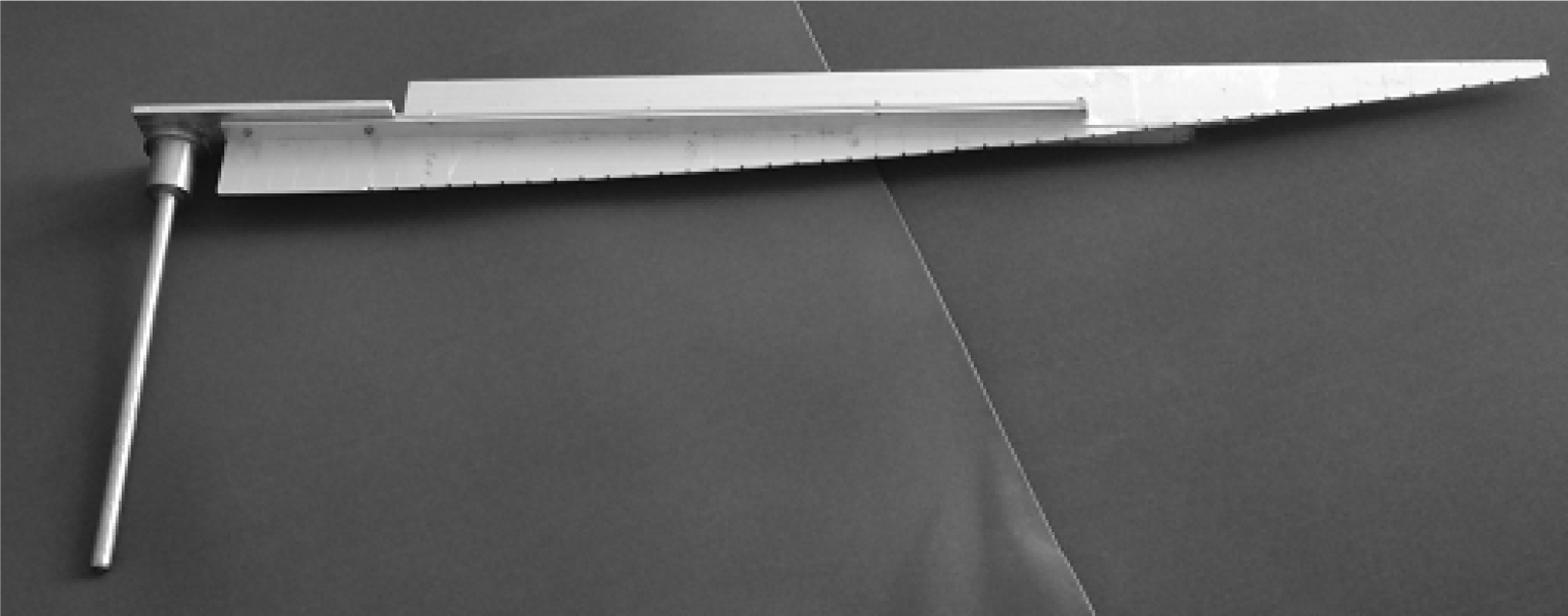
Gauge prototype
This gauge for parabolic surface adjustment is placed into the central tube 2 and can rotate. The screw positions are adjusted till contact with the edge of the gauge. Screw adjustment can be done manually or with an automatic system.
In Fig. 14 the gauge installation with frame structure is presented.

Support frame with parabolic gauge
Screw adjustment can be done with an automatic system as is demonstrated in Fig. 15.

Automatic arm controlled by means of computer vision: 1 – support frame; 4 - nut of adjustment; 6 - parabolic gauge; 9 - hold of automatic arm; 10 - rollers of support; 11 -roller of conduction 12 – tv camera
To accelerate the adjustment process we can use two parabolic gauges in parallel. Better results can be obtained with three gauges or six gauges.
Let us consider the process of a typical support frame cell assembly (Fig. 16). The components in Fig. 16 that must be assembled are marked with the numbers 1-12. All the components that are not marked form the preassembled part of the support frame. This part is fixed on the assembly device in a predetermined position.

Frame components to be assembled
The components that must be assembled are the following: first upper horizontal bar (1), second upper horizontal bar (2), first diagonal bar (3), first lower horizontal bar (4), second diagonal bar (5), second lower horizontal bar (6), vertical bar (7), lower hexagonal plate (8), upper hexagonal plate (9), third upper horizontal bar (10), third diagonal bar (11), third lower horizontal bar (12), central tube (13).
The assembly algorithm of the support frame is the following:
Install the vertical bar (7) in the assembly device in the correct position relative to the preassembled part. Fix the vertical bar (7) in its position.
Attach the lower hexagonal plate to the vertical bar (7) and fix it with the nuts.
Attach the upper hexagonal plate (9) to the vertical bar (7) and fix it with the nuts.
Attach the second upper horizontal bar (2) to the preassembled part and to the upper hexagonal plate (9) and fix it with two screws.
Attach the first lower horizontal bar (4) to the preassembled part and to the lower hexagonal plate (8) and fix it with two screws.
Attach the first diagonal bar (3) to the second upper horizontal bar (2) and to the first lower horizontal bar (4) and fix it with two screws.
Attach the first upper horizontal bar (1) to the preassembled part and to the upper hexagonal plate (9) and fix it with two screws.
Attach the second lower horizontal bar (6) to the preassembled part and to the lower hexagonal plate (8) and fix it with two screws.
Attach the second diagonal bar (5) to the first upper horizontal bar (1) and to the second lower horizontal bar (6) and fix it with two screws.
Attach the third upper horizontal bar (10) to the preassembled part and to the upper hexagonal plate (9) and fix it with two screws.
Attach the third lower horizontal bar (12) to the preassembled part and to the lower hexagonal plate (8) and fix it with two screws.
Attach the third diagonal bar (11) to the third lower horizontal bar (12) and to the third upper horizontal bar (10) and fix it with two screws.
After that we need to collocate the gauge/gauges on the central tube and make adjustments of the parabolic surface of the solar concentrator.
So, the whole assembly process for the solar concentrator includes 3 main steps:
Assembly of truss from its components (see above);
Adjustment of positions of the nuts to approximate a parabolic surface with flat triangle facets (mirrors) (see adjustment with parabolic gauge described above);
Installation and fixing of triangle mirrors on the truss.
At present we have the experience of manual assembly of the first solar concentrator prototype containing one mirror in each support frame cell, and experiments of manual assembly of the second concentrator prototype that contains 4 mirrors in each support frame cell. On the base of this experience we estimate that it will be necessary to spend approximately 30 seconds for every bar. The structure of the first prototype uses 7 bars for each cell with one mirror. So to make a solar concentrator with 2400 mirrors (slightly more than in the case of the Australian solar concentrator that has 2300) the assembly of the truss will demand 140 hours. Now, we have manufactured the second prototype of the truss that contains a cell of 7 bars for 4 mirrors. In this case we will need 35 hours for support frame assembly. In the future we plan to make the third prototype that has a cell with 10 bars for 16 mirrors. The assembly process of this truss will be near 12.5 hours.
Manual adjustment of one nut will demand approximately 20 seconds. The concentrator with 2400 mirrors needs 1440 adjustment nuts. So we will need 8 hours. The number of the nuts is the same for all three proposed truss structures.
We will need approximately 25 seconds to put a mirror in place and fix it. So we will need 16.7 hours.
The total assembly time for the first truss structure is 164.7 hours.
The total assembly time for the second truss structure is 59.7 hours.
The total assembly time for the third truss structure is 37.2 hours.
Let the surface area of one mirror be 0,0011 m2 (the side of the mirror is 50 mm). In this case the solar concentrator will have a total surface area of 2.64 m2. So for each square meter the assembly time for the first structure will be 62.39 hours/m2, for the second structure 22.61 hours/m2, for the third structure 14.1 hours/m2. If we suppose that the salary of the worker is 20 dollars per hour, the cost of the first structure assembly will be 1247.8 dollars/m2, for the second structure − 452.2 dollars/m2, for the third structure − 282 dollars/m2.
If we use manual assembly of a flat facet solar concentrator with triangular mirrors of 50 mm we lose the advantages that could be obtained from the flat faced structure of the concentrator.
Let us consider a concentrator with a triangular mirror size of 150 mm (the mirror surface area is approximately 0.01 m2 as in the Australian solar concentrator). In this case the assembly cost for the first truss structure will be 138.5 dollars/m2, for the second truss structure − 50.24 dollars/m2, for the third truss structure − 31.33 dollars/m2. So in this case it is worthwhile to make a flat facet solar concentrator even with manual assembly but the cost of manual assembly is still high. This fact has stimulated us to develop automatic assembly devices. At present we have started to develop the algorithms of automatic assembly.
In Fig. 17 we present the prototype of solar concentrator.

Solar concentrator prototype
New type of support frame for flat faced solar concentrator is developed. New method of the parabolic surface adjustment is proposed. We have developed the instruments (gauge/gauges) that allow us to do adjustment of the parabolic surface of solar concentrators much more easy than with the previous instruments.
Footnotes
6
This work was supported in part by projects PAPIIT IN110510-3, PAPIIT IN119610 and project of ICyTDF 330/2009. We thank DGAPA UNAM for a sabbatical grant.