
Abstract
This paper presents the complete development of the Simbiosis Smart Walker. The device is equipped with a set of sensor subsystems to acquire user-machine interaction forces and the temporal evolution of user's feet during gait. The authors present an adaptive filtering technique used for the identification and separation of different components found on the human-machine interaction forces. This technique allowed isolating the components related with the navigational commands and developing a Fuzzy logic controller to guide the device. The Smart Walker was clinically validated at the Spinal Cord Injury Hospital of Toledo - Spain, presenting great acceptability by spinal chord injury patients and clinical staff.
1. Introduction
1.1 Human mobility and affections
Mobility is one of the most important human faculties. It affects not only the individual's locomotion capacity but also the ability to perform certain tasks, affecting physiological and personal aspects and conditioning the conduct of an individual in his/her environment.
Different types of pathologies, such as poliomyelitis, spinal cord injuries, multiple sclerosis or trauma, affect the human mobility at different levels causing partial or total loss of such faculty. In addition, it is know that mobility decreases gradually with age as a consequence o neurological, muscular and/or osteoarticular deterioration.
Several people need devices to replace, maintain, recover and empower the individual's locomotion capacities. In this manner, the selection of an individual's mobility assistive device should be taken according to the pathology and to the degree of illness or physical disability of the individual, (17).
1.2 Mobility assistive devices
Considering the several types of conditions that affect human mobility it is necessary to take into account the level of motor impairment during the selection of a technical aid. In case of total incapacity of mobility, standing and locomotion, alternative solutions such as wheelchairs or special vehicles (e.g. scooters) should be addressed. Some examples of alternative devices are presented in Fig. 1. The robotic wheelchairs have been an intense focus of research during the last two decades. Autonomous and assisted navigation using several types of human-machine interfaces (HMIs) have been proposed in order to restore locomotion in many rehabilitation scenarios. Such researches have proposed a wide discussion in the scientific community and formed a doctrine body, the Autonomous Robotic Wheelchairs, ARW. Some examples of ARW are adressed in section 1.2.1 along with some types of special vehicles.

Some examples of alternative mobility devices.
It is known that the continuous use of wheelchairs can cause problems as such as joint stiffness, skin ulcerations, deformities in the spinal cord and physiological dysfunctions, all related to remaining in a seated position for long periods of time. For such reasons, the use of alternative devices should be avoided if the user presents certain locomotion capabilities preserved. Disabled people are usually encouraged by the rehabilitation staff to use augmentative devices which aim to empower the user's natural means of locomotion, the lower limbs, taking advantage of the remaining motor capabilities. This second group of rehabilitation devices can be classified into wearable - orthoses and prostheses - or external devices - canes, crutches and walkers Fig. 2 and Fig. 3. Currently, the augmentative devices are also a great focus of research and advanced / robotic solutions can be easily found in the literature. In section 1.2.2, some examples of advanced augmentative mobility devices are presented.

Some examples of wearable augmentative mobility devices.

Some examples of external augmentative mobility devices.
1.2.1 Alternative mobility devices
The alternative mobility devices are represented mainly by the wheelchairs and the special vehicles. Considering the commercial devices and research prototypes, the wheelchairs are, probably, the most commonly developed in the past years and they can be found in several modalities: with manual traction, all kinds of motorized traction, for sport practice, with standing-up functions, among others.
ARW are also very commonly found in research centres and Universities. Due to its great similitude with the mobile robots, an important part of the concepts and technologies in the fields of control and navigation could be almost directly applied to such assistive devices. In order to provide autonomous mobility to people in advanced stages of disability, advanced user-machine interfaces to drive the ARW have been developed. Some of the work done in this field is presented.
A great example of diversity in the use of human-machine interfaces to assist the navigation of a robotic wheelchair is the SIAMO Project (Fig. 4), (26). Developed in the Electronics Department of University of Alcalá, the SIAMO wheelchair is a system equipped with a set of sensors, such as a ultrasonic belt for obstacle avoidance, infrared sensors to detect stairs, and a on-board computer in which the navigation and control strategies are implemented. On top of that, a multimodal HMI is built in order to allow the command of the device through a number of different inputs. Besides from the conventional joystick, the HMI alternatives are, (26):
Breath Expulsion. A differential air flow sensor was designed to detect the strength and direction of the breath expulsion in a manner that it is possible to constitute a coded communication language. Such language allows the user to give different types of inputs and is suitable for driving the device in broad corridors and halls as crossing through 1.5 m wide doors without assistance of any other sensory system. Voice recognition. Nine voice commands were defined. The commands are previously recorded by each user and stored in a individual card that is introduced in the device before its use. Each command has an associated driving function - Stop, Forward, Back, Left, Right, Plus, Minus, Password, and Track. Head movements. A video camera installed in the front part of the wheelchair. Such camera records the user's face. As in the previous case, head gestures are associated to navigation commands and the used to drive the device. Electrooculography (EOG). The electrodes placed around the eyes measure the EOG potential that is used for steering the device through the interpretation of different commands generated by means of eye movements. Electroencephalography (EEG). More recently, EEG waves have been fed into a brain computer interface (BCI) and used to generate commands to drive the wheelchair. This solution presents an alternative to people with extreme motor disorders. To stablish the communication protocol that is used to command the device, a set of mental states previously trained by the user are detected and classified on-line.
Some ARW developed under the framework of the SIAMO Project.
A similar device with a mutimodal HMI was built at the Electrical Engineering Department of the Federal University of Espírito Santo, (4). In this case, the device can be commanded by eye-blinking (measured with electromyography) and a scanning interface, head movements (using an accelerometer or video camera), eye movements (using a camera) and EEG signals.
The use of EEG and BCI for controlling ARW was also theme of research at several other groups such as the Department of Mechanical Systems and Intelligent Systems from the University of Electro-Communications, (44), Japan and at the Laboratory of Brain-Computer Interfaces from the Institute for Knowledge Discovery, Graz University of Technology, Austria, (23).
Considering the commercial solutions, the CALL Centre Smart Wheelchair was developed with the focus on children with severe impairments, (29). The device allows the children to communicate, explore the environment, play and achieve a certain degree of independent mobility. The HMI is equipped with different types of inputs: push-buttons, scanning interfaces, conventional joysticks, among others. To provide safety to the user, collision sensors are also integrated into the system hardware. The device also has the functionality to navigate in structured environments by following marks place on the ground.
Similar to the wheelchairs, the special vehicles are also devices designed to replace human natural locomotion through the use of advanced robotic systems with the difference that such devices are usually designed to specific dysfunctions. Two examples of special vehicles are presented in Fig. 5. The Palmiber device is a special vehicle designed not only to provide autonomous mobility, but also for the cognitive rehabilitation of children with cerebral palsy, (33). Different modes of operation are programmed into the device to allow diverse levels of autonomy, varying from manually commanding the device to a complete autonomous navigation. To drive the device a multimodal human-machine interface is implemented, in which the children can use push-buttons, head switches with a scanning interface or even the head movements acquired with inertial sensors.

Special vehicles.
The Lazarim standing frame is a device developed to allow autonomous bipedestation and locomotion in a standing position (15). The patented system basically is a horizontal low frame in which the user places his feet, an operation that demands modest manipulation capability. Also, the user wears a dorsal harness in order to perform the elevation process. Two electrically actuated elevating bars, placed on a superior plane, elevate the user by means of the harness. Once the user is in a standing position, the locomotion functionality is performed by means of a conventional joystick. Currently, the system is in process of commercialization by ORTOTECSA S.A., Spain.
1.2.2 Augmentative mobility devices
As previously mentioned, there are two types of augmentative devices: wearable and external.
During the past years there has been a great research interest on the wearable robots, not only for rehabilitation and functional compensation purposes, but also for empowering human capabilities in healthy subjects, (31). These were originally called extenders and were defined as a class of robots that extends the strength of the human hand beyond its natural ability while maintaining human control of the robot, (20).
Considering the rehabilitation and functional compensation scenarios, orthotic robots and prosthetic robots are found. An orthosis is a mechanical structure that maps on to the anatomy of the human limb. Its purpose is to restore lost or weak functions, e.g. following a disease or a neurological condition, to their natural levels. The robotic counterparts of orthoses are robotic exoskeletons. In this case, the function of the exoskeleton is to complement the ability of the human limb and restore the handicapped function. A prosthesis is an electromechanical device that substitutes for lost limbs after amputation. The robotic counterparts of prostheses take the form of electromechanical wearable robotic limbs and make it possible to replace the lost limb function in a way that is closer to the natural human function. This is achieved by intelligent use of robotics technologies in terms of human-robot interaction (comprising sensing and control) and actuation (32).
The Otto Bock C-Leg prosthetic knee is an example of a state-of-the-art active prosthesis. It includes multiple sensors that transmit information at a speed of 50 Hz, allowing the feedback controller to operate its mechanical and hydraulic systems. Two strain gauges measure pressures on the leg and determine how often the heel strikes (thus giving an estimation of the walking cadence); magnetic sensors report changes in knee angle.
The Prolite™ Smart Magnetix™, manufactured by Biedermann OT Vertrieb, a German maker of prosthetic components, was developed jointly with Lord Corporation. The system includes both kinetic (force and torque) and kinematic (angular position and rate) sensors. The sensors are used to adapt the rheological characteristics of a modified Lord RD-1005 MR fluid damper, (27).
The system incorporates controllers that adapt the damping characteristics of the damper to the walking conditions. Thanks to the fast response time of the technology, this adaptation can be made very quickly (at a rate of 500 Hz), allowing for a more natural gait and making climbing up and down stairs and slopes much easier. Moreover, it makes for a more efficient walking pattern, which is one of the most serious problems suffered by users of passive prostheses, (27). Fig. 6 (a) shows a prosthesis user walking down a slope with the Prolite™ Smart Magnetix™ fitted.

Two examples of wearable augmentative devices.
An example of orthosis for functional compensation is the GAIT exoskeleton (28), shown in Fig. 6 (b). In such device, inertial information obtained from gyroscopes and accelerometers is fused to obtain limb orientation and to command a set of electromechanical actuators that assist the user's lower limb during gait.
External devices, such as crutches, canes and walkers are very commonly found in daily life. There are many variations of such devices according to the user's necessities, such as, patient's cognitive function, judgement, vision, vestibular function, upper body strength, physical endurance, and living environment, (45). Nevertheless, advanced or robotic versions of such devices are not as current as the wheelchairs. Usually, the robotic canes are more focused on assisting the user's navigation than offering physical support.
The SmartCane, (43), developed at the Massachusetts Institute of Technology uses a force/torque sensor installed on the device's handle to measure the interaction between the user and the cane mounted on a mobile robot (Fig. 7). Such inputs are converted into velocity and direction information by means of an impedance control implemented in a PC-104 mounted into the mobile platform. The system also counts with a CCD camera to assist navigation in structured environments and a sonar system for the detection and avoidance of obstacles.

The SmartCane.
2. Assessing and empowering natural mobility using walkers
Another device also oriented to assist in user's guidance is the GuideCane, (6). Such device is designed for blind user's to help in the avoidance of obstacles. The device is equipped with ultrasonic sensors, motorized wheels and a embedded processing platform to control the device. The user provides the desired direction by means of a thumb-operated mini joystick installed on the device's handle. Additionally, the device is equipped with a GPS navigation system to improve the guidance functionality outdoors.
Considering that the walkers are the main focus of this article, they are addressed separately in the next section.
Walkers improve balance by increasing the patient's base of support, enhancing lateral stability, and supporting the patient's weight.
There are many types of walkers, considering their constitutive materials, accessories, sizes and structural configurations. Nevertheless, an important aspect that classifies conventional walkers is the ground contact configuration. There are devices that only have legs, others with legs and wheels and, finally, three or four- wheeled walkers, (13).
In addition, G. Lacey presents a complementary classification of the standard walkers in three major types, (21). Standard Walking Frames or Zimmer Frames, Fig. 8 (a), are designed to provide a larger base of support to a person with lower limb weakness. Normally, these are four-legged devices. Special attention must be paid to the correct height of the frame to ensure good posture during gait.

Conventional walkers.
Rollators, Fig. 8 (b), are walking frames with wheels attached and there are many different configuration of base. Rollators are used where balance is the major problem rather than weight bearing. They are also used where upper limb strength is not sufficient to lift the walking frame on a regular basis. This device should be used if the patient requires a larger base of support and does not rely on the walker to bear weight. If a patient applies full body weight through the device, it could roll away, resulting in a fall, (45).
Reciprocal Frames are devices similar to the Standard Frames except that the frame is hinged on either side allowing the sides of the frame to be moved alternately, Fig. 8 (c). They are designed to accommodate a normal walking pattern with opposite arm and leg moving together. They are also used in domestic homes where space is confined.
In addition to the three types of walkers previously presented, there are the Front-Wheeled Walkers, Fig. 8 (d). These devices are a intermediary device between the Zimmer frames and the Rollators. Wheels permit the patient to maintain a more normal gait pattern than they would with a standard walker, but they also decrease stability. Van Hook et al. present a detailed study concerning the different types of walkers and their application to certain gait disorders, (45). Despite the enhanced support and utility for weight bearing, walkers also have disadvantages. These include difficulty manoeuvring the device through doorways and congested areas, reduction in normal arm swing, and poor posture with abnormal flexion of the back while walking. In general, walkers should not be used on stairs, (45). Conventional walkers also present problems related to the pushing energy required to move the device, the lack of stability and brake control (especially in Rollators) and the possibility of collision with obstacles.
In this context, to solve the previously presented issues, robotic or advanced walkers are a great focus of research in many groups, specially in the United States, Europe and Japan. Such devices - the Smart Walkers - aim at potentiating user's residual mobility capacities by means of advanced human-machine interfaces and controlled guidance. The following section will introduce some of the work developed in this field and a functional classification of the Smart Walkers.
2.1 Smart Walkers. Most significant devices, current trends and functional compensation strategies
The Smart Walkers provide assistance to the user at different levels, depending on the user's needs. Following, a functional classification of such devices is presented. After that, some examples of relevant devices found on the literature are given.
2.1.1 Physical support
By its nature and the kind of aid in question, almost the totality of the Smart Walkers has some kind of physical support function among its characteristics. There are manly two types of physical assistance: passive and active. In this first case, the objective is to introduce mechanical or structural enhancements to the device improving stability during gait. Usually, the improvements performed consist on the enlargement of base of the device or the balanced placement of heavy elements (motors, batteries, electronics, etc.) at lower planes of the walker increasing the dynamic stability.
Other passive change, not as commonly observed as the presented before, can be the replacement of the conventional handles (hand grip) of the walker by forearm support platforms. This reduces the number of unsupported degrees-of-freedom at the user's arms and increases the user's partial body weight support. This makes the device easier to push and, by increasing the friction component of the system, reduces the risks of glide.
Other possible enhancement concerning the reduction of gliding with the ground is the selection of materials with high coefficient of friction for the walker wheels.
Considering the walkers with three or four wheels, a common problem is the control of the device's free motion. More specifically, braking a conventional walker is a task that requires muscular strength, motor coordination and good reaction time, considering that these devices usually have a brake system similar to the installed on bicycles. If any of the before presented human faculties fail, there is a risk of an excessive acceleration of the device and a consequent fall.
In addition to the breaking problems, it is important to emphasize that the strength necessary to push the walker can be high depending on the degree of disability of the user. In this case, it is important to provide external and controlled pushing energy to the system.
Additionally, to prevent uncontrolled walker's motion, active physical support are commonly found on most of the Smart Walkers. Usually, these devices have motors installed on their wheels that are able to control the brakes, compensate gravity on inclined grounds and provide the pushing energy necessary to move the device. These motors are usually controlled by an advanced human-machine interface capable of detecting and interpreting the user's commands and translate them into motor actuation.
2.1.2 Sensory assistance
The Smart Walkers can also be used as elements to provide sensorial assistance to the user.
Normally, this function is performed through the installation and processing of ultrasonic, vision or infrared sensors capable of detecting static and dynamic obstacles. The control system assists the user to avoid them be it by sound or vibration alerts or directly operating the device's actuators, momentarily changing the path introduced by the user.
Normally, such sensory assistance functions are designed to help users with visual problems or to help navigation on environments with multiple obstacles occluded, many times, by the device itself.
2.1.3 Cognitive assistance
In this group, there are found the devices that assist user navigation and (auto-) localization in structured environments and outsides (using GPS, for an example). These Smart Walkers are very important to people that have cognitive issues and problems related to memory loss and disorientation.
Some Smart Walkers are programmed to followed predetermined paths inside clinics or achieve a certain location in a map of a house or medical facility. Other devices are capable of creating maps of an unknown environment or auto-localization in a map using markers placed on the surroundings.
Also, some Smart Walkers can communicate bidirectionally with the user through a visual interface or voice commands, receiving directions from the user, or informing the same about the present localization in a map and the environment conditions, such as obstacles.
2.1.4 Health Monitoring
In more specific situations, Smart Walkers can be used to monitor some health parameters of the user. This health information is used to keep a medical history of the user or inform through a wireless communication network a health center or the medical staff in the case that an emergency situation is detected.
2.2 Relevant Smart Walkers found on the literature
Specially considering the elderly, walker can suffer from multiple health conditions. In such cases, more than one of the before mentioned functions are needed. For that reason, many of the Smart Walkers on the literature are multifunctional.
A good example of a multifunctional walker is the Mobil, (7). The developed device is designed to offer extra support to the user through the use of forearm support platforms and motorized rear wheels. Also, it can be commanded by a remote control or follow the user if he/she uses an active belt that sends ultrasonic signals to the walker. This walker uses a second set of ultrasonic transducers to detect and avoid static and dynamic obstacles, acting as a sensorial assistance device.
Nevertheless, the most representative Smart Walkers and referenced in several scientific papers are the PAM-AID (with all its versions), PAMM SmartWalker and the MARC Smart Walker. Such devices, shown in Fig. 9, are presented in the following paragraphs. The Personal Adaptive Mobility Aid (PAM-AID) is robotic mobility aid designed to augment the independence of people that have visual impairments and mobility problems, (22). Several versions of the PAM-AID Smart Walker were developed. Some of them are presented in Fig. 9 (a).

Some of the most representative Smart Walkers.
One of the main objectives of the PAM-AID is to offer maximum control of the platform to the user. In this manner, the PAM-AID has no motorized locomotion. The electronic system only controls the orientation of the front wheel, based on the guidance information acquired by an intuitive user interface. Such user interface is similar to the handlebar of a bicycle that can rotate ±15°. The handlebar is spring loaded and when no torque is applied it will return to its zero position.
To assist on the guidance of visually impaired people, the device is equipped with ultrasonic or laser sensors depending on the version of the device. Also, information about the environment state is provided by the walker in the form of two types of voice messages: one regarding the description of the environment and another message informing the user about the presence of obstacles.
The PAM-AID has two operation modes, (24). The first one is the manual. In this case, the system never controls the steering of the device, only providing the two types of voice messages. The second operation mode is the assistive, in which the device provides the voice messages and, in addition, controls the front wheel avoiding obstacles.
In the year 2000, Haptica Ltd. started the commercialization of the PAM-AID Smart Walker. The Department of Veterans Affairs (USA) purchased five devices and introduced some minor modifications and evaluated the safety and performance of the device, renaming it as the Veterans Affairs Personal Adaptive Mobility Aid (VA-PAMAID), (34).
In another commercialization intent, the PAM-AID was renamed GUIDO Smart Walker, (41). The device became more aesthetically attractive, ergonomic and some new functions were included. A third mode of operation, parked mode, also present on the VA-PAMAID, was introduced. In such mode, the front wheel of the device is positioned to break it in order to assist the transfer of the user from a chair. Map navigation, mapping and auto location techniques were also introduced, (40). Considering the user interface, the spring loaded handlebar was replaced by force sensors used to identify navigational intents of the user, (41).
Other relevant development is the Personal Aid for Mobility and Monitoring (PAMM), (43). The PAMM comes in two versions. The cane-based device (PAMM SmartCane) was previously presented in section 1.2.2. The Smart Walker version is shown on Fig. 9 (b). The PAMM SmartWalker is designed to offer extra support for walking, guidance, scheduling (reminding the time to take medicines, for an example) and health monitoring for elderly users. The main idea is to provide a complete system to help the elderly in the normal problems of the senility, such as loss of memory, disorientation, musculo-skeletal weakness, lack of stability during gait and monitoring of vital signals such as electrocardiogram (ECG). Also, the device features enable it to be used as rehabilitation device for younger patients.
The PAMM has a set continuous health monitoring sensors. These sensors can detect short term changes as well as long term health trends. It can record the user's activity level (speed and applied forces). Such measurements can help physicians to better monitor the user's health during regular operation of the device. A robust ECG-based pulse monitor was developed for the SmartWalker. Experiments were also performed using the force/torque sensor of the PAMM systems along with odometry information to study the user's gait and to detect risks of falls.
For the locomotion, the device is equipped with four wheels; two of them are castor, and the other two motorized omni-directional wheels. This way, the PAMM SmartWalker can move on a plane in any direction, improving the manoeuvrability in confined indoors spaces. Three types of sensors are used in order to control the navigation of the device: a sonar array, a CCD camera and tridimensional force/torque sensors. The sonar array installed on the front of the device is used in order to avoid obstacles. The CCD camera is used to detect marks placed on the ceiling of a structured medical facility or nursing home. Finally, the force/torque sensors installed on the handle of the walker are used to capture the user's navigational intents, the level of support and to determine stability parameters of the user when pushing the device.
An important question approached in this device is how to give the maximum control to the user taking into account the possible cognitive degenerations of the user. On the one hand, the PAMM walker can be fully guided by the user, trough the application of forces/torques on the handles of the device. On the other hand, it is capable of navigating automatically in a structured environment.
The solution adopted was a shared control algorithm that takes a greater control of the device when the user starts to diverge from the path calculated by the electronic system. Initially, the user has to introduce a destination.
The system generates virtual forces/torques that are proportional to the deviation of the programmed path. Such forces and torques are added to the forces applied by the user and an admittance controller converts the resultant forces and torques on motor velocity moving the device.
The Medical Automation Research Center (MARC) Smart Walker, (47), is a device based on the modification of a commercial three-wheeled walker, Fig. 9 (b). Tridimensional force/torque sensors were installed on the walker's handle to measure the interaction between user and the device. Based on the forces and torques applied, the current state of the walker and the environment conditions (measured by sonar and infrared sensors), the control architecture of the MARC Smart Walker estimates two signals called user intent and walker intent. The control logic balances these two signals in order to generate the control of the orientation of the front wheel. Similar to the PAM-AID, the MARC walker doesn't have motorized locomotion. The pushing energy has to be supplied by the user.
An interesting study was realized with the MARC walker and a camera motion analysis system in order to determine gait characteristics from measured forces and moments, such as the heel strike, toe-off, double support, and single (differentiating from right and left foot) support detection, (3).
More recently, research projects are also focusing on the development of systems to assist the bipedestation process. D. Chugo presents an advanced walker in this context, (9), (10), (11). The user, at sitting position, places his/her arms on a supporting platform that is elevated during the standing process assisting the user in the operation. Once in standing position, DC motors also assist the device's navigation following user's commands.
Similar to that, the devices named WHERE I and II were developed focusing on different actuator technologies to assist the standing operation, (42). At this level, the Smart Walkers start to merge with other groups of devices, such as the gait trainers, expanding the number of possible users and the rehabilitation scenarios.
3. The Simbiosis Walker. Concepts, implementation and clinical validation
In this section, the Simbiosis Walker is presented. The device, developed under the research project with the same acronym, focuses on enhancing comfort, safety and stability during gait. This is proposed through the development of a multimodal HMI responsible for the acquisition and interpretation of user's postures and gestures during gait. Both upper and lower limbs information are combined in order to command the device's motion. Such interaction signals are classified and turned into motor commands using fuzzy logic. Finally, the system was taken for experimental validation at the National Hospital of Paraplegics - Toledo, Spain.
3.1 Simbiosis Project. Human-machine interaction concepts
The robotic walker developed under the framework of the Simbiosis Project presents two sensor subsystems designed for the acquisition of gait parameters and for the characterization of the human-robot interaction during gait, (16). First, the upper-body force interaction subsystem, is based on two tridimensional (3D) force sensors installed under the forearm supporting platforms Each 3D force sensor is compound by one MBA400-200Lb biaxial sensor by Futek and one Transdutec TPP-3/75 load cell with their respective amplifiers. The biaxial sensors are used for measuring the X (lateral direction) and Y (advance direction) components. The load cells measure the Z component (vertical direction).
The second subsystem is compound by ultrasonic (US) sensors to measure the user's feet evolution during assisted gait. One piezoelectric US receiver is installed on each user's feet and an emitter is placed on the walker structure. Through direct transmission, the evolution of the distance between user's feet and walker is measured and several parameters regarding user's gait and walker motion are determined.
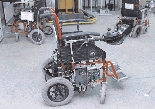
Figure 10 illustrates how both sensor subsystems are installed on the walker's structure. Force and ultrasonic sensors are integrated into a real-time architecture based on Matlab Real-Time xPC Target Toolbox. When data storage is required (e.g. for offline studies), a laptop computer is also introduced into the system's architecture. The laptop PC also adds the possibility to control the system externally through a wireless LAN remote desktop connection.

The Simbiosis Walker and its subsystems
During the first experiments performed with the developed device, no motorized locomotion was introduced with the goal of characterizing the typical signals obtained from the multimodal interface. The subjects recruited for such experiments presented no history of any dysfunction on either upper or lower limbs.
A study regarding the forces acquired during experiments of assisted gait lead to the identification of three main components in force signals: the vibrations introduced by floor/walker wheels imperfections, oscillations due to user's trunk motion during gait and the voluntary components related to the user's navigational commands. This led to the development of a technique for obtaining and characterizing such components, (19).
Additionally, US distance signals were used for characterizing feet evolution, gait parameters and, most importantly, to improve the reliability of the filtering architecture developed for obtaining user's guidance commands, presented in the next section.
3.2 Adaptive real-time filtering for the identification of user's guidance intentions
The typical force data acquired on the y axis of one of the force sensors is presented in Fig. 11. As it is shown, in the instants that the subject is not walking but has his/her arms resting on the forearm supports (green boxes in Fig. 11), no high frequency noise is observed. This indicates that the high frequency components are generated during the movement of the device. As observed by the authors, such noise is caused by vibrations introduced by both irregularities on the ground and imperfections on the surface of the walker's wheels.

Typical force signal (Y-axis) obtained experimentally.
3.2.1 High-frequency noise cancellation filter
In addition, during the moments in which the subject is walking (red box, Fig. 11), slower oscillations are also observed in all axis of force data. In previous works, the authors demonstrated that this oscillatory component is specially observed in the vertical direction of the force data, and is a result of the lateral displacements of user's trunk, (2). Such oscillations are translated into forearm reactions as the user is supported by the walker. Movements of user's trunk and, consequently, user's center of gravity (CoG) are highly correlated with gait phases, (49). In (18) and (1), the authors proposed a methodology for the extraction of gait parameters, such as heel-strike, toe-off and cadence, from this force component.
Finally, other events related to user's navigation commands are also found within the force sensor data previously presented. Considering that force sensors were installed in walker's handles for the identification and characterization of user's guidance intentions, such transient components must be properly extracted in order to generate commands that drive walker's motion.
Next sections introduce a methodology for the extraction of the components related to user's guidance intentions. Such methodology is based on the filtering diagram presented in Fig. 12:
The upper branch is designed for the cancelation of high-frequency components that result from vibrations caused by wheels/floor irregularities. The lower branch is constructed to estimate in real time the component caused by user's trunk oscillations and, therefore, highly correlated with user's cadence. This last component is, then, subtracted from the force data filtered by the first block.

Filtering architecture presented in this work.
As it can be seen, in addition to the force signals, cadence is also an input for this filter. The idea is to selectively and adaptively filter the force data without compromising the amplitude of components which frequencies are close to gait cadence as they can contain relevant information regarding user's intents. For that matter, a cadence estimation method based on the US signals is also presented in section 3.2.3.
This section presents a filtering architecture that relies on the high-frequency of the force components related to the vibrations of the walker's structure. As it is known, classical low-pass filters can be used for the cancellation of high-frequency components of the acquired force signals. Nevertheless, such approach would also introduce an important phase shift between input and outputs signals causing a temporal delay on the filtered signal. Such situation is undesirable in real-time applications once delay affect the cognitive interaction between the walker and the user.
To overcome such limitation, an approach based on g-h filters is proposed. G-h filters are simple recursive filters that estimate future position and velocity of a variable based on first order model of the process. Measurements are used to correct these predictions, minimizing the estimation error. Traditional applications of g–h filters are radar tracking and aeronautics, (8). The general form of a g–h filter is described in the following equations.


Equations 1 and 2 are designated as update, tracking, or filtering equations. They estimate the current position, x k,k , and velocity, ẋ k,k , of the variable based on previous predicted position, xk,k-1, and velocity, ẋk,k-1, taking the current measurement y k into account. Confidence on measures is weighted by gains g k and h k . Equations 3 and 4 are called prediction equations as they provide a prediction of future position and velocity, xk+1,k, ẋk+1,k, based on first order dynamic model of the variable. As g-h trackers consider a constant velocity model, predicted velocity ẋk+1,k is equal to the current one, ẋ k,k . The assumption of constant speed is reasonable considering that human movements are slow, presenting small accelerations, (25), and that the data is sampled at high rates (in this study, f sampling = 1kHz).
G-h filters are affected by two error sources, (8): (i) the lag, dynamic, bias or systematic error, which are related to the constant velocity assumption, and (ii) the measurement error, which is inherent to the sensor and measurement process. Typically, the smaller g k and h k are, the larger is the dynamic error and the smaller are the measurement errors, (8). In designing a g-h tracking filter there is a degree of freedom in choice of the relative magnitude of the measurement and dynamic errors.
To simplify the selection of filter gains (g
k
, h
k
), two filters that are optimal in some sense are considered. These filters are the Benedict-Bordner Filter (BBF) and the Critically Dampened Filter (CDF). BBF minimizes the total transient error, defined as the weighted sum of the total transient error and the variance of prediction error due to measurement noise errors, (5). BBF is the constant g-h filter that satisfies:

As g and h are related by Equation 5, the BBF has only one degree of freedom.
CDF minimizes the least-squares fitting line of previous measurements, (8), giving old data lesser significance when forming the total error sum. This is achieved with weight factor θ. Parameters in the g-h filter are related by Equation 6. Selection of filter gain for the CDF is analogous to that for the BBF.

For the selection of the filter and for tuning of the the correspondent parameters, the Kinematic Estimation Error (KTE) was used, (Equation 7). KTE quantifies the transient response through

Where,
The KTE was used for the selection of the filtering parameters for BBF and CDF: g and θ were modified within a broad range, using a small step, and the best solution was selected for each user, experiment and repetition in validation experiments performed with healthy subjects. Mean KTE of (2.035 ± 0.358) · 10−2kgf and delay of (1.897 ± 0.3697) · 101ms were obtained for the BBF, while mean KTE of (1.951 ± 0.350) · 10−1kgf and delay of (2.413 ± 0.131) · 101ms were obtained for the CDF. As the KTE in both cases are very similar and the delay is still significantly smaller for the BBF, this filter showed to be a better solution than CDF for the data obtained from the experiments performed in this work.
3.2.2 Estimation of force component related to gait cadence
Once the filter for cancelation of high-frequency noise is introduced, this section presents a methodology for the estimation of the force component related with user's gait cadence. For that purpose, taking advantage of the periodicity of cadence, an adaptive filter based on the Fourier Linear Combiner (FLC) was applied.
FLC is an adaptive algorithm used for continuous estimation of quasi-periodical signals based on a M harmonics dynamic Fourier model (Equation 8). Using frequency and number of harmonics as inputs for the model, the algorithm adapts amplitude and phase for each harmonic at the given frequency.

The adaptation of the coefficients w
k
is performed based on the least-mean-square (LMS) recursion, a descend method based on a special estimate of the gradient, (48), which ensures inherent zero phase. The equations for the FLC algorithm are described below.


Where:
y
k
is the input signal. M is the number of the harmonics used in the model. μ represents the amplitude adaptation gain used for the LMS recursion.
As mentioned before, the FLC algorithm needs a frequency input for the correct estimation of the gait related force component. Next section describes the developed methodology for the real time estimation of gait cadence.
3.2.3 Real time estimation of gait cadence from ultrasonic signals
The authors demonstrated in (18) that the vertical components of the force signals can be used for continuous estimation of gait cadence using the Weighted-Frequency Fourier Linear Combiner (WFLC). Nevertheless, in that application the algorithm needed to be tuned individually for each subject.
Also, the experiments were performed in a controlled environment on top of a treadmill. In outdoors and, specially, dealing with a more diverse population the use of foot-walker distance signals experimentally demonstrated to offer a more robust real time estimation of gait cadence. The WFLC method was adapted to this situation.
Taking into account the typical form of the distance signal obtained (Fig. 13), the method for cadence estimation is presented. The WFLC is an extension of the FLC noise canceller presented before and also tracks frequency of the input signal based on a LMS recursion. Therefore, the WFLC adapts in real-time its amplitude, frequency and phase to the reference signal, (37). It is based on IEEE-STD-1057, which is a standard for fitting sine waves to noisy discrete-time observations. The WFLC is also built upon the least-mean-square (LMS) recursion, a descend method based on a special estimate of the gradient, (48). This ensures it has inherent zero phase, thus allowing for real-time implementation.

Typical foot-walker distance signal obtained from the ultrasonic system
The WFLC recursion minimizes the error ɛ
k
between the input s
k
and the signal harmonic model, (12). It assumes that the distance measured by the ultrasonic sensor can be mathematically modelled as a pure sinusoidal signal of frequency ω0
k
plus M harmonics, (36).

The WFLC provides an estimate of instantaneous frequency:


The WFLC is formulated as follows: (15) represents the sinusoidal signal model, which consists of M harmonics of the fundamental frequency, ω0
t
. The error which the algorithm uses to adapt itself to the input signal is described in (16). Frequency and amplitude weights update based on the LMS algorithm (48) are expressed in (17) and (18) respectively.


The algorithm has 5 parameters to be tuned: The number of harmonics of the model, M, which is fixed to 1, the instantaneous frequency at initialization, ω0,0, the amplitude and frequency update weights, μ0 and μ1, and a bias weight, μ b , to compensate for low frequency drifts, (35).
As the WLFC is designed to adapt to the dominant-frequency component in a signal (38), it is important to perform a previous stage of band-pass filtering (compatible with gait cadence frequencies) for the correct performance of the WFLC. Although this filtering stage can cause undesirable time delay in the force signals, instantaneous temporal changes in gait cadence (WFLC's frequency output) are minimal. Therefore, an external branch of cadence estimation based force measurement, and the WFLC algorithm showed to be very useful in the application presented.
Thus, the combination of WLFC and FLC presents great advantages, (36). The band-pass filtering allows the WFLC to robustly adapt to the values of gait cadence, while the FLC operates on the raw input, ensuring zero-phase amplitude estimation. Fig. 14 shows the complete diagram of the filtering architecture. The cadence estimation stage, here presented, is shown in the purple area.

Complete filtering architecture.
As it is shown, each distance signal is filtered individually and the averaged to ensure good signal estimation. The outputs of the FLC block is connected depending whether the amplitude of the WFLC estimation signals are greater than a threshold (green area), indicating that there is a cadence signal. This is done due to the fact that a zero signal can have any value of frequency and zero amplitude.
Once the complete filtering architecture was developed, values were set for the coefficients of the WFLC and FLC blocks. These values, obtained experimentally for healthy subjects, were:
WFLC. M = 1, ω0,0 = 0.3 (the lower cut-off frequency of the band-pass filter), μ0 = 3 · 10−5, μ1 = 1 · 10−3 and μ
b
= 0. FLC. M = 2 and μ = 2 · 103
The authors would like to mention that the selection of values for μ affects directly the convergence time and, most importantly, the bandwidth (BW) of the FLC adaptive filter, (46). For values of μ ≪ 1, the bandwidth is given by BW ≈ 2μ.
This filtering methodology led to an amplitude cancellation of approximately 80% of the gait related components, (19). Fig. 15 presents the effect of the filtering method on the force signal introduced in Fig. 11. The filtered signal (red in Fig. 15) is used for guiding the robotic walker through the control strategy presented in the next section.

Signals at different stages of the filtering architecture.
3.3 Users' intent classification and control strategy
The force signals filtered with the previously presented algorithm were used to drive the walker's motion through a classifier and controller based on fuzzy logic. Figure 16 illustrates the developed methodology. Both y-axis and z-axis force components from both right and left sensors are filtered individually using the filtering architecture presented in Fig. 14. Afterwords, y-components are divided by the z-components in order to obtain force signals that are proportional to the amount of body weight applied in each armrest. This feature is specially important in cases of asymmetrical support caused by a unilateral affection on gait. Then, signals are conditioned to enter the fuzzy logic classifier by means of:
a gain, to adjust to the correct range of inputs; a saturation block, to avoid signals over the input limits and a dead-zone, to prevent motor commands in cases of signals very close to zero and, thus, not high enough to move the device.

Fuzzy logic based classifier and controller developed for the Simbiosis Walker.
After the fuzzy logic block, following explained, the signals are passed through the output conditioning block that does a low pass filtering to avoid eventual abrupt changes in control signals and adjusts the signals to the range of inputs of the motor control board. The fuzzy logic block is the main element of the previously presented block set. It is built upon the information obtained experimentally from the tests performed with healthy subjects. It combines information of right and left sensors to generate motor commands.
Force signal inputs can vary from −1 to 1 and are grouped into four classes:


Three functions were defined to the outputs:
Zero, Z-shaped function with a = −0.2 and b = 0.5. Positive
low
, Gaussian symmetrical function with σ = 0.1944 and c = 0.5. Positive
high
, S-shaped function with a = 0.5 and b = 0.8.
Due to safety reasons, no backward motion was allowed. This will be implemented in the future and will only be active in special situations determined by the patient's needs.
Sixteen rules convert the inputs into outputs, (14). The developed control strategy was implemented into the device's firmware and the system was taken for clinical validation as it is described in 4.
4. Clinical validation of Simbiosis Walker
The Simbiosis Walker was experimentally validated in the Biomechanical Unit at Spinal Cord Injury Hospital of Toledo (HNPT). Eight patients were selected by the clinical staff taking into consideration some inclusion factors:
To have preserved cognitive functions, To be able to maintain a standing position, To be able to walk 10 m without the assistance of another person and with or without help of an assistive device, To be able to grasp.
Subjects were divided into three groups based on the degree of disability using the Walking Index for Spinal Cord Injury - WISCI II, (12). The first one was composed by two subjects (JLG and GDT, both WISCI II = 12) with more severe affections in the lower limbs. In this case, the use of a walker is something ambitious as this subjects use almost exclusively wheelchairs as their assistive devices. In this group, the aim was to evaluate the Simbiosis Walker as a rehabilitation device.
The second group, formed by four patients (BRT, DGC, RAB and AGG, all WISCI II = 16), is the main focus of the developed device. The patients, in this case, use mainly the wheelchair, but usually can walk for short periods of time with the assistance of a device. Nevertheless, usually the existent technical aids do not provide a satisfactory experience and the risks of fall is important. This causes the subjects to use the wheelchair almost exclusively. The aim, here, is to evaluate the developed walker as a functional compensation device.
Finally, the third group is formed by two patients (AML, WISCI II = 19, and BCM, WISCI II = 20) with the least affections in gait. Both of them used conventional two-wheeled walker at some point in their rehabilitation and can give very important insights about the Simbiosis Walker.
The experiment consisted in walking in a U-shaped track, which means walking on a straight line for about 10 m, performing a right or left turn and walking again for 10 m. All patients were able to use the device and walk the proposed track with their own preferred speed. No instructions or training was given in order to prepare the subjects for the proposed task and no personalization of the controller was performed in order to adjust the device to the subject.
The filtering architecture, previously presented, provided a mean real-time amplitude cancellation of 73.18% percent of the cadence related force components, which is very close to the 80% obtained with healthy subjects and no controlled motion presented in (19). This also considering that the body weight support levels were much higher in the case of the patients comparing to the healthy subjects.,
The developed controller based on fuzzy logic offered smooth and responsive motor commands. Fig. 17 shows raw signals obtained from the Y-axis of both right an left force sensors, the filtered force signal and the velocity of motorized wheels during the experiments.
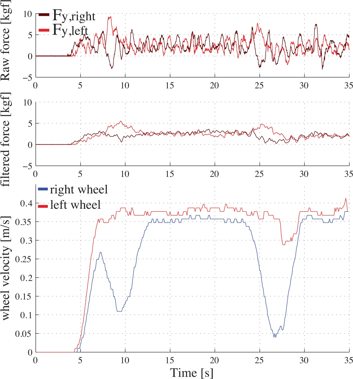
Force signals and wheel velocities obtained from the clinical experiments in HNPT.
A survey was passed by the clinical staff to get user's feedback for the developed Smart Walker (0 = worst score, 100 = best score). The first four questions regarded the manoeuvrability (Q1 - motion start, Q2 - straight walking, Q3 - performing turns, Q4 - motion stop), the fifth one (Q5) was about security and the last one (Q6) was related to posture and comfort. Table 1 presents the obtained results.
Survey results from the clinical validation.

5. Conclusions
This work presented the full development done under the Simbiosis Project. In such research project, the Simbiosis Walker was developed.
First, the authors introduced a classification of the mobility assistive devices, including some examples of conventional and research devices. Following that, this work focused on the walkers and a review of some the most significant works developed on the Smart Walkers field was presented.
Then, the concepts of the Simbiosis Project is presented with the implementation of the human-machine interfaces and the interaction strategies. The authors developed a technique for the identifications and separation of different components found on the force sensor data based on adaptive filtering. Such technique made it possible to isolate the components related with the navigational commands and use them to control the device using a Fuzzy logic based controller.
The device was clinically validated at Biomechanical Unit, Spinal Cord Injury Hospital of Toledo - Spain. Great acceptability was observed by the patients and clinical staff which motivated the creation of a new version of the Simbiosis Walker, NeoAsas, intended to be commercialized.
Currently, a great effort is being done in order to simplify the human-machine interface and to develop such commercial version of the device. Additionally, the interaction concepts developed under the Simbiosis Project are also being used in other research device, the Standimovi Gait Trainer, currently in development at the Bioengineering Group - CSIC.