
Abstract
Knowing that the driving task of a conventional wheelchair could be difficult or even impossible for impairment people, this work presents an overview of some strategies developed to aid these people. Within this context, a myoelectrical eye-blink and an iris tracking system to guide a robotic wheelchair are briefly described. Futhermore, some comments about EEG-based systems are also presented. Finally, it is presented a robotic wheelchair navigation system capable to reach a desired pose in a planar environment while avoiding static and dynamic obstacles.
1. Introduction
There are many people with either lower and upper extremity impairments or severe motor dysfunctions. It is quite difficult or even impossible to them to drive a conventional wheelchair. Then, an alternative to help these people to overcome the difficulties is to develop a robotic wheelchair system. Such system commonly integrates a sensing subsystem, a navigation and control module and a user-machine interface to guide the wheelchair in an autonomous or semi-autonomous way. In the autonomous mode, the robotic wheelchair goes to the desired place without the user involvement in the vehicle control. However, in the semi-autonomous mode the user shares the high-level control with the robotic wheelchair system. In this case, the user should be able to use some motor skills. For safety navigation of the robotic wheelchair, both modes need an obstacle avoidance strategy for unknown obstacles, which can be static or dynamic. Some human-machines interfaces (HMI) used to guide a robotic wheelchair in a autonomous or semi-autonomous way and an aid navigation system are presented in the sequence.
The most important evaluation factors for robotic wheelchair systems are safety and ease of operation. Some improvements can be obtained by providing autonomy to the system. There are many works dealing with the obstacle avoidance based on infrared, ultrasonic, vision, and other sensors using a robotic wheelchair ((1; 2; 24; 26)). In all the researches, the ultimate goal is to develop a wheelchair that automatically takes the users to a desired pose. However, in addition to going to certain designated places, sometimes we wish to displace in the environment as freely as possible. Thus the system should be capable of doing it. In this case, a good human interface becomes the key factor. Instead of a joystick, like on conventional power wheelchairs, voice can be used in issuing commands ((25; 29; 46)). In the Wheelesly robotic wheelchair system ((52)), the user can control it by choosing a command icon focusing his/her gaze on the screen. A set of five electrodes is placed on the user's head for both measuring eye movements and detecting the command choice. In the work developed by (27), They use the face direction to transmit the intentions of the user to the system. Besides, autonomous navigation capabilities are also implemented based on ultrasonic sensors and a environment observing camera, placed strategically in the robotic wheelchair.
In our proposed system, as the work developed by (3), it is used myoelectrical eye blinks, iris-tracking and brain-computer interface to choose symbols in a Personal Digital Assistant (PDA) and to start an action. The PDA presented in Figure 1(a) and 1(b) is installed onboard the wheelchair in such a way that it is always visible for the impaired individual seated on. It provides a graphic interface containing the possible options for the operator, including the pre-programmed movements of the wheelchair, a virtual keyboard for text edition, and symbols to express some basic needs or feelings of the impaired individual, such as sleep, drink, eat, feel cold, heat, etc. For all these cases, a specific option is selected using a procedure to scan the rows and columns in which the icons are distributed in the screen of the PDA (once the desired screen is presented). A voice player confirms the option chosen, providing a feedback to the user and allowing the communication with people around as well.
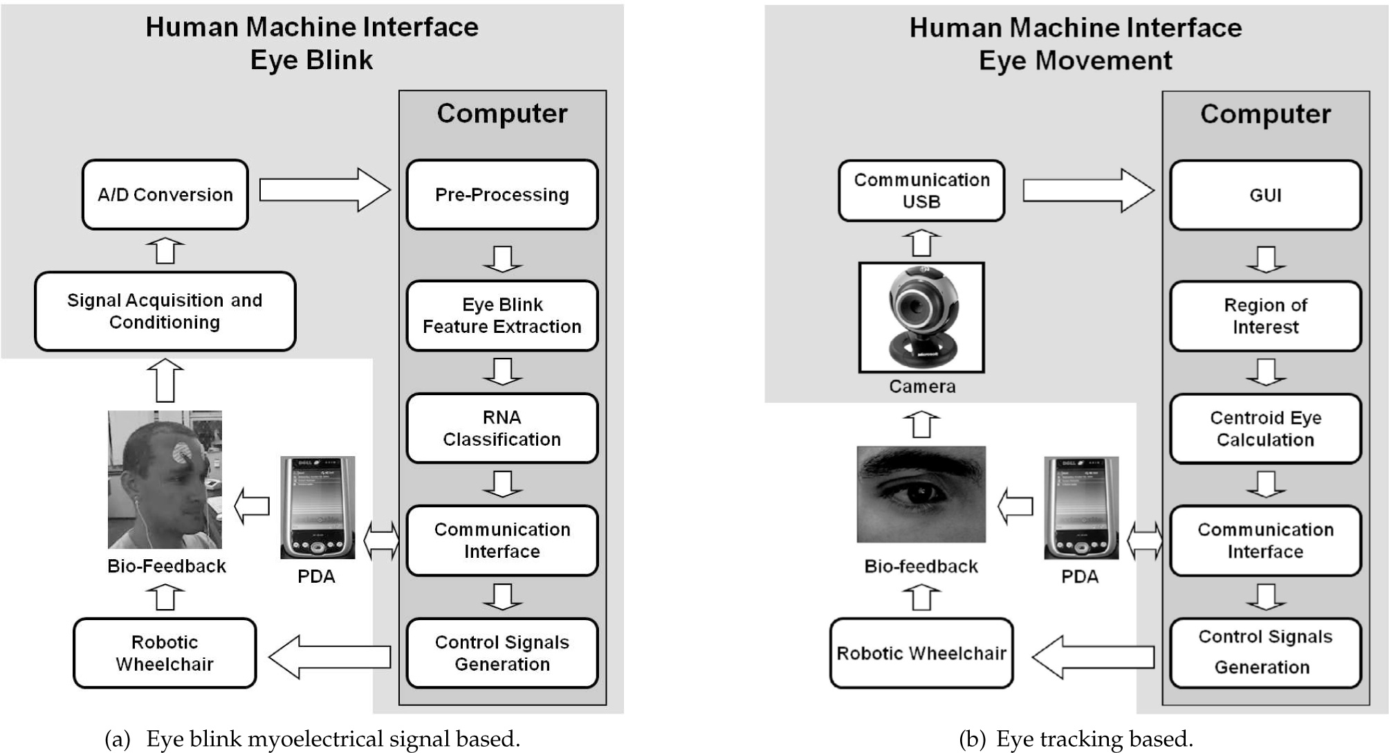
The structure of the proposed HMI.
2. Myoelectrical eye blink signal system
This system idea consists of recognizing the eye blink, contained in Myoelectrical Signal (MES) acquired on the specific places in the face. A set of electrodes are located as shown in Figure 1(a), in order to record signals in a differential way. In other words, the differential signal is obtained by using electrodes above the right and left eyes and another one in the ear (which is used as reference, due to the absence of muscle interferences). Figure 2 shows typical eye blinking signals.
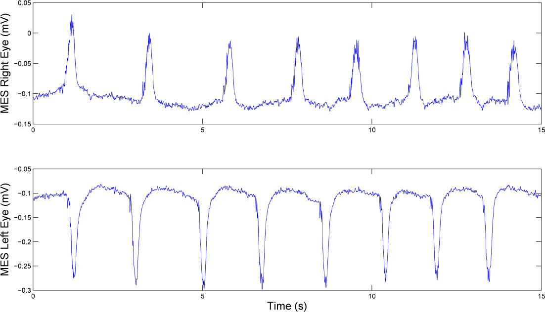
Typical eye blinking signals.
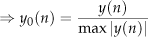
After recording the myoelectrical signal, the algorithm (1) is implemented to find the peaks and the position of the eye blink signal in the preprocessed MES samples. Results are shown in the Figure 3. In order to avoid detection of natural eye blinks, a threshold is established to disregard signals lower than 35% of the maximum peak. Below such threshold, a blink is regarded as a noise and it is thus disregarded in the system.

Results using the algorithm based on Pan-Tompkins method, where y0 is the standard signal; y1 is the signal after application of the derivative of Pan-Tompkins; y2 represents the square of the input signal and y3 the signal after the implementation of an integrated mobile window filter.
The next step of the system is to determine the time-interval of the eye blink, based on the peak detection. An angular variation approach using tangent computation is used in y3(n) to determine the behavior near the peak and then to indicate the start-end point of an eye blink.
Finally, an Artificial Neural Network (ANN) classifier is trained to recognize right, left and natural eye blinks. In order to compare the performance of back-propagation algorithms in this problem, Bayesian Regularization (BR), Resilient Backpropagation (RP) and Scaled Conjugate Gradient (SCG) are here used. A set of 630 preprocessed samples of right and left eye blinks and random noises (used to emulate natural eye blink) is used for training and validation process. The ANN structure adopted is 40-4-3 for the input, hidden and output layers, respectively. After training and validation process, an accuracy of 99.6% is obtained using RP algorithm.
A mobile robot Pioneer 2-DX simulator is used to validate the proposal. It is worthy to mention that such vehicle has the same kinematic model of a wheelchair. In the simulation environment developed in MATLAB, the user can choose either the presence or absence of obstacles in the navigation scene, as well as to determine the position of such obstacles. It is also possible to vary the linear and angular velocities of the mobile robot, by choosing a velocity that best matches the processing effort of the computer used, providing easy visualization of the real-time simulation. Figure 4 shows the desired and traveled path executed by the mobile robot according to the commands generated by the Automatic Eye-blink Recognition (AER) system.

Simulation result: At left: A table of desired and recognized blink commands to follow a specified path using the proposed AER system. At right: Path traveled by the mobile robot Pioneer 2-DX during the simulation.
Figure 1(a) shows the structure of the interface based on the eye blinks used to guide a robotic wheelchair in a semi-autonomous way.
Receive eye-blink sample ⇒ y(n)
Find the greatest absolute peak of the input signal ⇒ max |y(n)|
Normalize the input signal
Apply Pan-Tompkins derivative

Compute the energy of the signal

Filter y2(n) using an integrated mobile window filter

3. Iris-tracking system
Despite the effectiveness presented by the system described in the Section 2, there are some problems associated to the eye blinks, such as muscle spasms and the inability to perform an eye blink (due to severe motor disabilities, for example). In such context, it is proposed a HMI based on the iris-tracking shown in Figure 1(b).
A webcam (strategically adapted in a goggle, as can be seen in the Figure 5) delivers digital images from the eye, whose iris should be tracked. First, a threshold is applied to discern the iris from the other parts of the face (Figure 6). However, in order to avoid eyebrows and eyelashes detection, morphologic and edge filters are also applied to enhance regions of interest of the image. In such case, Random Circular Hough Transform (RCHT - (34)) and the Canny filter are used. Thus, each binarized image circle is parameterized by two values (x c , y c ) representing the coordinates of its center. Assuming initially that three pixels of coordinates (x, y) are on the edge of the image, at a certain distance, empirically determined, it is possible to calculate the RCHT. Figure 7 illustrates an example of detecting the center of the circle.

Webcam strategically adapted in a goggle.

(a) Original image. (b) Binary image.

(a) Example of a circle with points detected on its edge. (b) Lines drawn from randomly selected points on the edge of the circle and the intersection of perpendicular lines on the center of the circle.
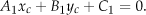
Thus, considering the distance between two points, one has


Simplifying (2), one gets

Observing Figure 7, one realizes the first equation is perpendicular to the line passing by the midpoint P1, which results
Applying the same technique to the middle point P2, one gets

From (4) and (5), the center is defined by

After determining the center and radius by (8), the region of interest (ROI) of the iris is obtained from the average of the centers found by the RCHT, and the mean radius determined from the average of the radius. Figure 8 illustrates the application of the technique described.

Iris image obtained from the application of the Canny filter. Highlights, center obtained from the average of the centers calculated using the RCHT.
Despite the ease in obtaining the parameters of the circumference, the calculation of the centroid is affected by illumination influences, making the path traced very noisy. In order to smooth such effects, a Kalman filter is applied in the coordinates x c and y c . Figure 9 illustrates a eye-tracking task showing the coordinates of the centroid of the ROI obtained with and without applying the filter.

Original coordinates x c and y c from the ROI, and the same coordinates filtered using the Kalman filter.
The HMI used to select symbols in a pictographic display is based on MES, where the eye-blink is replaced by the iris displacement. In contrast with the previous approach, the interface based on eye tracking proved to be a simple and inexpensive alternative compared with commercial systems in the literature. By using the Canny filter combined with the Random Circular Hough Transform, it was possible to detect the iris of the eyeball and thus determine a region of interest, decreasing the influence of eyebrows and eyelashes in the calculation of the centroid of the iris. The use of the Kalman filter enabled fine-tuning the eye-tracking movement.
4. EEG-based systems
In cases of major severity, neither eye or iris movements can be reliably recorded. In such a case, the electroencephalogram (EEG) could provide sources of information for HMI. In fact, all EEG-based HMI systems share the same source of information: the evoked potential (EP). In response to external sensorial stimuli the brain responds with an EP. These responses carry important information about its respective sensory pathway and are also useful in posterior fossa tumor ((20; 48)), audiometry ((17; 44)), activation in epilepsy ((4; 7)) and monitoring surgery ((38; 50)). Since the signal-to-noise (SNR) of brain EPs are usually low when immerse in the electroencephalogram (EEG), only the evaluation of such responses over several repetitions may reveal its time and spectral contents. If the stimuli are presented at a low repetition rate, then there is sufficient time between stimulus and each individual response arises and vanishes within this interval. This kind of response is called transitory EP and is suitable for analysis of the response's waveform e.g. delay of propagation and peaks. According to (8), the upper rate limit to elicit such responses is about 2 Hz. When the stimuli are presented with a sufficiently high rate, each transient EP overlaps in time and the frequency content of the response basically lies on the frequency of the stimulus. So, a steady-state EP is obtained in this case.
When someone uses the EPs - e.g. related to sensory or imaginary tasks and recorded from the scalp - to promote the control of devices, such a strategy is called Brain Computer Interface (BCI) ((12; 18; 30)), as shown in Figure 10. BCI aims at accomplishing a direct communication between patients and their external environment, especially peoples with several motor limitations ((22)). All BCI investigations share two principal signal processing steps: feature extraction and classification ((35; 40)). In the first step, many mathematical techniques are used to give information from the EEG data. Among those techniques, one can mention: band powers ((43)), Power Spectral Density (PSD) ((9)), time-frequency features ((51)), autoregressive (AR) models parameters ((42)). Among techniques used in BCI, the most relevant to interpret and classify features are: linear classifiers ((37)), neural networks ((19)), and nonlinear Bayesian classifiers ((31)). Appointed as a promissory technique, a nonlinear Bayesian classifier known as Hidden Markov Model (HMM) can be used to modeling spontaneous electroencephalogram (EEG) events to BCI application ((39; 47; 49)). Furthermore, the Magnitude-Squared of Coherence (MSC) has shown good results to objective response detection during sensory stimulation ((11; 14; 36)) and imaginary movement ((45; 49)).

The structure of a typical BCI.
5. Robotic wheelchair navigating system
As mentioned before, a robotic wheelchair system is commonly constituted of a sensing subsystem, a navigation and control module and a human-machine interface to guide the vehicle in a autonomous or semi-autonomous way ((5; 15; 33; 41; 53)). Both methods are proposed to aid handicapped people during their navigation in a structured or semi-structured environment, while avoiding static and dynamic obstacles.
Nowadays the strategy to avoid dynamic obstacles can be split into two approaches, that are model- and learning-based ((10)). The first one uses mathematic models to represent the movement of the vehicle and the movement of the obstacles in the environment as well to describe collision possibilities, and finally to give a solution to avoid them. By its turn, the learning-based approach applies the knowledge obtained in real situations to “learn” the way to avoid dynamic obstacles.
Considering obstacle avoidance tasks for robotic wheelchairs, in (28) an assistance control mode generates a collision-free path in a smart structured environment. In (13) a sonar array gives the proximity information in a semi-structured environment and the distance relationship between the wheelchair and the closest static obstacle is used in a force-feedback control through an analog joystick. In turn, in (32) a supervisor algorithm takes the distance information of the ultrasound sensors to decide about the safety of the control signals sent to the wheelchair through an analog joystick. If there is any collision risk the control action is disregarded (canceled). The occupation grid technique is used in (21) to define the direction of greater freedom for navigation of the robotic wheelchair. In this case, the filling of the occupation cells is done according to measurements provided by 3D infrared laser sensors.
In this section, an obstacle avoidance strategy to avoid both static and dynamic obstacles in a semi-structured environment is proposed. The model-based approach is used to represent the movement of the obstacles. In contrast with (10), where a main obstacle (which is the closest to the vehicle or the fastest in the collision course) is selected and then the safe path is defined; here all obstacles are considered to define the avoidance pathway. A weighting factor c k , similar to the fictitious force strategy ((23)), is used to give more importance to the closer and faster obstacles, with respect to the wheelchair. Another important contribution is the local mapping which provides 360 degree distance information around the vehicle (named virtual omnidirectional sensor) thus improving the tangential escape strategy when only static obstacles are considered. Also, the physical dimensions of the wheelchair are taken into account in all calculations, i.e., the vehicle is not considered as a point in the environment anymore. Thus it is possible to predict which part of the border of the vehicle is closer to an obstacle. In addition, the position of the laser scanner (in the front part of the vehicle) in relation to the control point is also dealt with. Finally, it is important to mention that a stability analysis of the system is also performed, based
On the other hand, when dynamic obstacles are presented in the navigation scene, it is necessary to find the obstacles in the workspace and to identify which of them are moving. In order to compute the resulting velocity vector, it is assumed that the proximity measurement vector delivered by the laser scanner is a discrete function, which on the Theory of Lyapunov, considering an analytical approach for the saturation of the control signals sent to the robotic wheelchair.
First, the control algorithm designed looks for a desired point, which can be a specific place in a house. Then, a laser scanner onboard mounted in the front part of the vehicle is used to estimate the position and the velocity of the obstacles in a semi-structured environment. Once the movement model of the obstacles is estimated, the collision points between the robotic wheelchair and the obstacles are calculated. In the presence of dynamic obstacles, the obstacle avoidance strategy sets the commands of velocity based on such collision points allowing the wheelchair overtakes the most critical obstacle or waits to be overtaken by it, i.e., increasing or decreasing the vehicle velocity, respectively.
Considering a navigation between to points, a robotic wheelchair should seek for a goal while avoiding any obstacle during navigation. Any obstacle inside a circle of radius d obs around the vehicle (named safety zone) should be avoided by using the tangential escape strategy ((16)). After leaving the obstacle behind, the vehicle resumes the search for the goal. If no obstacle is found inside the safety zone, the vehicle keeps navigation towards the target. One can note that after avoiding the obstacles in the environment the distance wheelchair-target is continuously reduced until reaching the target.
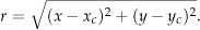
As proposed in (6), the control algorithm is asymptotically stable in the sense of Lyapunov, once the kinematics model of the vehicle is considered during the design of the controllers. Figure 11(b) illustrates the position control scheme used to reach a desired position in the environment, which can be specific places in a house. In other words, each room defines coordinates that should be reached by the robotic wheelchair in a intelligent house. It is worthy to highlight that the desired position is constantly updated during an avoiding obstacles tasks.
The test platform developed in the Laboratory of Intelligent Automation of the Federal University of Espírito Santo, Vitória -ES, Brazil.
In order to avoid static and dynamic obstacles during navigation, the proximity information is given by a laser scanner onboard the vehicle. Such range sensor is mounted on the front part of the wheelchair, and delivers 181 range measurements at a sample rate of 10Hz, with 1 degree of resolution, covering a semi-circle in front of the vehicle.
When only static obstacles are considered, the tangential escape strategy proposed in (16) is here implemented to provide a safe path through reactive navigation (without previous planning), whose main idea is to follow paths that are tangential to the boundary of the obstacles being avoided.
can be differentiated. Figure 12(a) illustrates a laser scan of the workspace, at a specific time-instant, and its discrete derivative.

The strategy to identify dynamic obstacles and to predict its velocities.
Looking at Figure 12(a) (on top), an obstacle can be identified in the laser scan whenever a beam returns a value lower than the maximum one adopted (in this case, dmax = 5m). However using the difference between two consecutive polar measurements, as shown in Figure 12(a) (on bottom), one can observe a negative peak followed by a positive one, which indicates when the detection of an obstacle starts and ends, respectively.
Figure 12(b) illustrates the obstacles identified in the instants k and k + 1. knowing their position in two consecutive instants and the sample period of the system, it is possible to compute their velocities, once it is possible to relate O k [k] with O k [k + 1]. The arrows shown in Figure 12(b) indicate the velocities of the obstacles, which are used to define the collision points with the vehicle, and then to establish the safer path to it.
In such proposal, all obstacles are considered to define the avoidance pathway and a weighting factor is used to give more importance to the closer and faster obstacles, with respect to the wheelchair. Commonly, the laser scanner sensor is mounted in the front of the wheelchair, providing range measurements for the horizon of 180° ahead it. Its position in the vehicle creates blind zones where it is not possible to detect obstacles, such as, for example, the both sides of the wheelchair robot. Such blind zones can cause lateral collisions during navigation and/or abrupt obstacle detections during vehicle rotation, thus affecting directly the performance of the obstacle avoidance strategy. To improve the obstacle avoidance strategy, it is also proposed a local mapping, which creates a virtual omnidirectional sensor, responsible to provide 360 degree distance information around the vehicle.
It is important to highlight that the physical dimensions of the wheelchair are taken into account in all calculations, i.e., it is not considered as a point in the environment anymore. Details of this proposal can be found in (6).
A robotic wheelchair simulator developed in Federal University of Espírito Santo is used to run the simulations and validate the proposal. It is important to mention that such simulator runs in real time and considers the dynamic model of the vehicle, not only its kinematics.
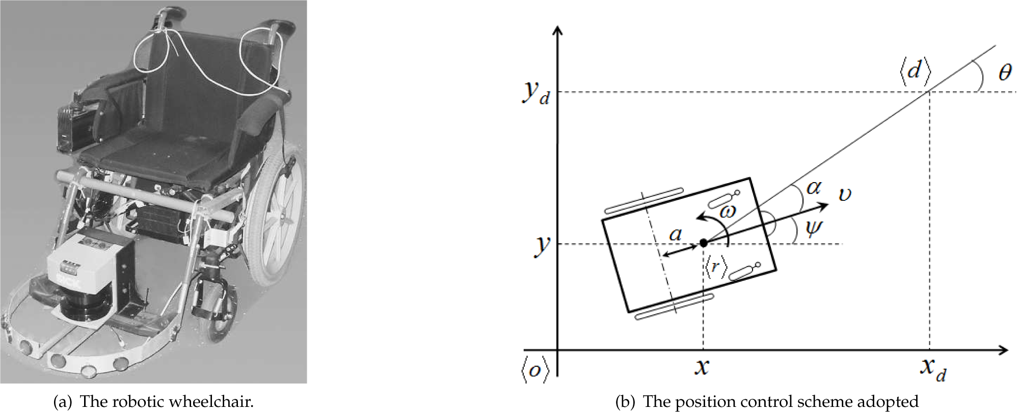
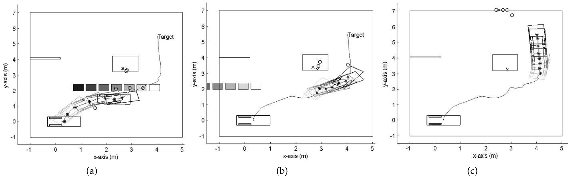
In every simulation the robotic wheelchair starts in the position (0m, 0m) and should reach the target in the coordinates (4m, 5.5m) while avoiding static and dynamic obstacles. The semi-structured environment used in the simulations has one static obstacle located in the position (2.75m, 3.7m) and the walls around the vehicle. A dynamic obstacle initially positioned in the coordinates (4.9m, 2.2m) in the first simulation, and in the coordinates (3.7m, 2.2m) in the second one, moves from right to left with a constant velocity
The simulations were split and presented in three parts for a better understanding, and with a sample time of 2.5 seconds, a snapshot is taken to illustrate the current situation of the navigation. Figure 13 shows the path traveled by the vehicle (solid line) during the execution of the task and the movement of the obstacle (from the white to the black rectangle). In this simulation, one can note that the robotic wheelchair avoids the dynamic obstacle passing in front of it. The cross and circle marks shown in such figure indicate the estimated position of the obstacles. When one of the marks is not shown in Figure 13, it indicates that the dynamic obstacle is not “seen” anymore by the laser scanner. It is also important to mention that the star mark represents the control point h. In contrast with Figure 13, Figure 14 shows a situation where the wheelchair wait that the dynamic obstacle overtakes it. It is also important to highlight that in both simulations, the robotic wheelchair avoids the static obstacles safely (including the walls of the environment), even when the laser scanner cannot detect possible obstacles. In such cases, the local mapping is extremely helpful with regard to safe navigation.
Simulation Results: Robotic wheelchair overtaking the dynamic obstacle and leaving the static obstacle behind.
Simulation Results: Robotic wheelchair waiting to be overtaking by the dynamic obstacle and reaching the target after avoiding the static obstacle.
6. Concluding remarks
This work proposes an aid navigation system and some human-machines interfaces, used to guide a robotic wheelchair in an autonomous or semi-autonomous way. In such context, we use myoelectrical eye blinks, iris-tracking and brain-computer interface to choose symbols in a Personal Digital Assistant and to start an action. The first system presented consists of recognizing the eye blink, contained in Myoelectrical Signal acquired on the specific places in the face by a set of electrodes. In the second system, some problems associated to the eye blinks, such as muscle spasms and the inability to perform an eye blink (due to severe motor disabilities, for example) are solved by using an iris tracking based system composed by a webcam (strategically adapted in a goggle), which delivers digital images from the eye. In the sequence, some comments about Brain-Compute Interface are also done for situations where neither eye or iris movements can be reliably recorded. In such cases, the electroencephalogram provides sources of information for HMI through evoked potential. Finally, it is presented an obstacle avoidance strategy to avoid both static and dynamic obstacles in a semi-structured environment, which aids handicapped people during a autonomous or semi-autonomous navigation of the robotic wheelchair.
7. Acknowledgments
The authors thank CNPq, CAPES, FAPEMIG and FAPERJ for supporting this work.