
Abstract
This paper presents a minimum-time path planning scheme for life-extending operation of legged robots, illustrated with a six-legged walking robot (hexapod). The focus of this study is on extending the bearing fatigue life for leg joints. As a typical treatment, the minimum-time path planning is performed through a bisecting-plane (BP) algorithm with the constraints of maximum joint angular velocity and acceleration. Based on bearing fatigue life theory, its fatigue life increases while the dynamic radial force on the bearing decreases. By imposing more rigorous constraint on the dynamic radial force, the minimum-time path planning algorithm is thus revised by reinforcing the constraint of maximum radial force based on the expectation of life extension. A symmetric hexapod with 18 degree-of-freedom (DOF) is adopted as the illustrative example for simulation study. The simulation results validate the effectiveness of possible life extending with moderate compromise in transient performance.
1. Introduction
Robot reliability has drawn increasing attention, especially for mobile robots (Stancliff et al., 2006). Many mobile robots in practice have poor reliability, requiring frequent maintenance and repair. Historical failure data for small field robots reveals that they are either broken or under repair approximately half of the time (Stancliff et al., 2006). In this study, we approach the robot reliability problem by focusing on a particular class of mobile robots, the legged robots, and especially from a different perspective: extending the operating life of joint bearing on legged robots by improved the joint path planning.
A lot of research has been conducted for the optimal control and path planning of robots. Gu and Hu (2006) presented a receding-horizon (RH) model predictive control (MPC) for tracking control of a non-holonomic mobile robot online. Jan et al. (2008) proposed an optimal path planning algorithm for navigating mobile rectangular robot through obstacles. It is also worthwhile to mention a neighboring research, known as life-extending control (LEC). The LEC is intended to achieve an optimized trade-off between dynamic performance and structural durability of the plant under control. Ray et al. (1994) presented a damage-mitigating control (DMC) or LEC scheme to extend the life of complex mechanical systems.
Bearings are important elements in rotating machinery as well as for robots (Zhou et al., 2009). For mobile robots, bearings undertake most load and motion of the associated joints. Therefore, the system (robot) performance and reliability are strongly affected by the health of the bearings. This study is focused on the life extending operation of legged robots with degraded (but not failed) joint bearing. Our research has been strongly motivated by legged robot for terrain and underwater survey and monitoring. For the idea-proof purpose, a radially symmetric hexapod as shown in Fig. 1 is adopted as illustrative example. The kinematic redundancy of such robots trades agility for good reliability for longer term field operation.

The Hexapod with AX-12 Servo Motors
For the hexapod in this study, the relationship between the proximal and distal joint angles on the leg and body posture can be found through the forward and inverse kinematics analysis. The dynamic model can be built with the Newton Euler equation. For the minimum-time duration path planning at each joint, the bisecting-plane (BP) algorithm in (Piazzi & Visioli, 1998) is applied with the constraints in maximum angular velocity and acceleration imposed.
The key idea of the reported work is to revise the joint minimum-time path planning scheme only through imposing the load constraints according to the need for extending the life of joint bearing(s). It is a well-known fact that the fatigue life of bearings can increase with reduced load level (Liao & Lin, 2003; Harris, 2006). More specifically, for ball or roller bearings, the dynamic radial force is a major factor affecting the expected life. A bearing fatigue-life model is used to determine the constraint for dynamic radial load, based on the relation between the fatigue life and dynamic radial load. Without loss of generality, ball bearing is assumed for all leg joints of the hexapod, while systems with other types of bearings would bring little difference.
The remainder of the paper is organized as follows. The BP algorithm based minimum-time path planning is presented in Section 2. In Section 3, the model for the fatigue life of ball bearings is described, followed by the life extending oriented modification of the minimum time path planning with BP algorithm. Section 4 presents simulation results of life-extending minimum-time path planning for a pair of supporting legs. Section 5 concludes the work with discussion.
2. Minimum-Time Path Planning For Hexapod
The static stability of hexapod requires that at least three supporting legs are needed (Wu et al., 2010; Erden & Leblebicioglu, 2007). The supporting legs undertake most load during the hexapod motion, and thus are considered for the life-extending oriented path planning. To achieve faster walking and body adjustment on uneven terrains for observation, the supporting legs are required to include one symmetric pair of legs (i.e. with orientations differing by 180°) as shown in Fig. 1.
Assume that particular hexapod tasks, e.g. body posture adjustment for walking or downward observation, have been derived through gait planning, kinematic and dynamic analysis. The joint path planning for the supporting legs is then concerned. Fig. 2 shows the freebody diagram for the relevant dynamic modeling of the hexapod. Due to the length limitation of this paper, detailed derivation of the dynamic models for the central body and the supporting legs are omitted here. They can be found in our recent work (Wu et al., 2010). The Newton-Euler equations are used to establish the force and moment equations for the symmetric pair of supporting legs.
For the symmetric pair of supporting legs, i.e. legs i (i = 1, 2, or 3) and i+3, we assume identical magnitudes of the dynamic radial forces at the respective proximal joints (joint 0), i.e.

Such treatment helps achieve similar degradation rates on each joint bearing, which may facilitate the maintenance. Then, the dynamic radial force exerted on the links of supporting legs can be solved via Eq. (1) and the force and moment equations derived in (Wu et al., 2010).

Free body diagram of simplified 2D structure for supporting legs
For the minimum-time path planning for the joints on the legs, we have adopted the BP algorithm that Piazzi and Visioli (1998) applied to some m-joint manipulators based on an interval procedure. The time duration for the whole joint path can be minimized through the BP algorithm with the constraints, e.g. maximum angular velocity and acceleration on each joint of the supporting legs, i.e.

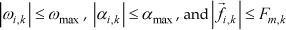
where i = 1, …, s, 3⩽ s ⩽6, and k = 0, 1. The proximal and distal joints are set as joints 0 and 1, respectively.
The BP algorithm is used to obtain the minimum time duration in a given joint path planning. A value of time duration is accepted as a feasible solution if all the relevant kinematic and dynamic variables during the path planning are bounded within the imposed constraints. If any of designated constraints is violated, the value of time duration is considered as unfeasible solution, and it needs to be increased. The time duration that can merely makes all constraints satisfied is set as the critical point, i.e. the minimum time duration solution. The procedure for obtaining the minimum time duration is summarized as follows.
(1) Obtain h− and h+ as unfeasible and feasible solution in the joint path planning as searching boundary, respectively.
(2) Set ɛ = (h+ - h−)/2 and h1 = h− + ɛ. Replace h− by h1 if h1 is an unfeasible solution in the joint path. Replace h+ by h1, when h1 is a feasible solution in the joint path.
(3) Repeat steps (2) with k = 2, 3,… N, until h k and hk+1 are both feasible solutions, and hk-1 is the unfeasible solution.
(4) Set h− = hk-1 and h+ = h k . Go to the critical-point procedure given below.
The critical-point searching procedure is given as follows.
(1) Set H j = h− + ξ, where h s is the sampling time, and ξ = j · h s (j = 1, 2, …, integer [(h+ -h−)/h s ]-1) is the searching interval.
(2) Find H j and Hj+1 corresponding to the unfeasible and feasible solutions of time duration in the given joint path, respectively. Hj+1 is thus the critical point in the joint path.
(3) End the searching procedure, and d:= Hj+1 is the minimum-time duration for the given joint path planning.
3. Life Extending Minimum Time Path Planning
3.1. Fatigue Life Model for Ball Bearing
The fatigue life (L) of a rolling element bearing is defined as the total number of shaft rotations at the start of a fatigue failure. Figure 3(a) shows the cross section of a ball bearing with the ball-race contacts unloaded, where ψ is the bearing angular position, αo is the contact angle under no load, δ r is the total elastic deformation in the radial direction, subscripts i and o denote inner and outer raceway, ξ is coordinate of the center of the raceway in the x direction, ζ is coordinate of the center of the raceway in the z direction, g is the distance between the bearing center and the curvature center of the raceway (Liao & Lin, 2003).

Ball bearing and fatigue life dependency on dynamic radial force (Liao & Lin, 2003).
For ball bearings, the fatigue life of inner raceway at bearing position angle ψ is
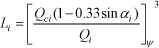
where Q ci is the basic dynamic capacity of the inner raceway, Q i is the normal force of the inner raceway, α i is the contact angle of the inner raceway, and ψ is the bearing angular position. For the non-rotating outer raceway, its life at angular position ψ is

where Q co is the basic dynamic capacity of the outer raceway, and Q o is the normal force of the outer raceway.
The fatigue lives of the balls in the inner and outer raceways are

where Q bi is basic dynamic capacity of a ball at inner raceway, and Q bo is the basic dynamic capacity of a ball at outer raceway.
In order to determine the fatigue life L of a ball bearing, the lives for the bearing elements including the rotating inner raceway and the non-rotating outer raceway, and the balls must be considered together, i.e.
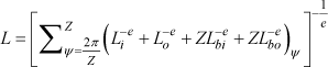
where Z is the number of balls and e is 10/9 for point contact.
In this study, the dynamic radial force exerted on the links of the supporting leg is related to the normal force of the inner and outer raceway at joint ball bearing on supporting legs. Based on Eqs. (3)–(6), the joint ball bearing fatigue life can increase while the corresponding dynamic radial force decreases.
3.2. Life-Extending Oriented Minimum Time Path Planning
Based on the fatigue life model of ball bearing given in the previous subsection, the bearing fatigue life, or approximately the joint operational life can increase by reducing the constraint for the maximum dynamic radial force on ball bearing. As illustrated in Fig. 3(b), assume that the load limit is originally set as F A , which corresponds to the fatigue life of L A . If we consider extending the bearing/joint life to L B , we can derive the load limit F B based on the fatigue life model in Eqs. (3) through (6).
With constraints of the reduced dynamic radial force limit at each joint on supporting legs, the life extending minimum-time path planning for each joint can be obtained through modifying the minimum time path planning algorithm as shown in Section 2. In the modified algorithm, the constraint of maximum dynamic radial force at Joint 0 and 1 on supporting legs can be added into constraints given in Eq. (2), i.e.
where F m is the maximum dynamic radial force at each joint.
With such modification, the fatigue life of the joint ball bearing may be extended to perform the same tasks only with different joint path, with possible trade-off of slower motion.
4. Simulation Study
The proposed idea of life-extending oriented path planning is evaluated through simulation study on the hexapod platform shown in Fig. 1. The values of Q i and Q o at each joint on the supporting legs can be given as

Through Eq. (1) and the force and moment equations, we can obtain the normal force of the inner and outer raceway at the joint ball bearing on supporting legs. Since the parameters of the joint ball bearing are assumed constant, the values of Q ci , Q co , Q bi , and Q bo in Eqs. (3) through (6) do not change.
The following parameters are determined from the specifications of the central body and the AX-12 servo motor on each joint of a leg in the hexapod platform:

As example, for the downward observation of an underwater hexapod, assume that the hexapod body is tuned to a special position. The 2nd and 5th legs are chosen as the symmetric pair of supporting legs. The reference angle trajectory for each joint is designed via the quintic polynomial (Shintaku, 1999):

where d is the time duration.
With the specifications of joint motors, the constraints for the angular velocity and acceleration of each joint are shown as:

Through the BP algorithm in Section 2, the minimum time duration in the quintic polynomial path is obtained as 1.0 second with the given constraints shown in Eq. (10).
Based on Eqs. (3) through (6), the maximum dynamic load needs to reduce by 10% if we expect to extend the joint ball bearing fatigue life by 37%. The constraints of the dynamic radial force limit at each joint on the supporting legs is added into the life extending minimum-time path planning algorithm shown in Section 3.B.

where F max,0 is 6.54 N and F max,1 is 7.60 N.
The simulation results for the second leg are shown in Figure 4. The life extending minimum-time duration is obtained as 2.3 sec with given constraints as shown in Eq. (11). This verifies that the same task can be performed while taking longer time.

Simulation results for the second leg for two conditions

Simulation results for the second leg for faster motion
To demonstrate the effectiveness for faster motion, more powerful joint motors are assumed for the hexapod model in Fig. 1. The constraints for the joint path are changed into

where F max,0 is 8.1 N and F max,1 is 9.3 N.
With these revised constraints, the simulation results for the second leg are shown in Figure 5. Similarly, to extend the joint ball bearing fatigue life by 37%, the minimum-time durations under the normal and life-extending constraints are derived as 0.6 and 1.3 sec, respectively. Again, the tradeoff in time duration is clearly shown.
The above simulation results show that the proposed idea can increase the joint fatigue life by reducing the maximum dynamic radial force on leg joints.
5. Conclusion
This paper presents a life-extending oriented minimum-time path planning for legged robots, with illustrative study for a hexapod robot model. As joint bearings are the most vulnerable component for legged robot, the study is converted into extending the joint bearing life based on the available bearing fatigue model. The BP based minimum-time path planning algorithm is adopted, and the Newton-Euler equation based dynamic model is used for deriving the minimum-time solution. For the ball bearings selected for the illustrative study, the dynamic radial force is used as the fatigue indicator. The maximum dynamic radial load is then added as extra constraint into the BP algorithms along with the constraints in joint angular velocity and acceleration. Two simulation cases, one slower and one faster, showed that the proposed idea may extend robot joint life with moderate degradation in the time duration.
A more interesting extension to the reported work is to determine the life-extending oriented revision of the bearing load with sensor feedback for wear monitoring. Based on historical degradation data for joint bearings, the predicted life extension will be more accurate. Nevertheless, the presented work based on empirical fatigue life model is also an acceptable solution when actual degradation data are absent. A good analogy for the reported research might be the age-based adjustment of exercise intensity for a senior person, while degradation data based approach would be more like adjusting exercise intensity by heart-beat, respiration and joint feeling.
6. Acknowledgement
This work was supported in part by China “the Fundamental Research Funds for the Central Universities” with the Project (11QG06 and 11QG07).