
Abstract
Progress is constantly being made and new applications are constantly coming out in the area of field robotics. In this paper, a promising application of field robotics in football playing fields is introduced. An algorithmic approach for generating the way points required for the guidance of a GPS-based field robotic through a football playing field to automatically carry out periodical tasks such as cutting the grass field, pitch and line marking illustrations and lawn striping is represented. The manual operation of these tasks requires very skilful personnel able to work for long hours with very high concentration for the football yard to be compatible with standards of Federation Internationale de Football Association (FIFA). In the other side, a GPS-based guided vehicle or robot with three implements; grass mower, lawn stripping roller and track marking illustrator is capable of working 24 h a day, in most weather and in harsh soil conditions without loss of quality. The proposed approach for the automatic operation of football playing fields requires no or very limited human intervention and therefore it saves numerous working hours and free a worker to focus on other tasks. An economic feasibility study showed that the proposed method is economically superimposing the current manual practices.
Keywords
1. Introduction
Field Robotics have been proved reliability in many different areas such as in rehabilitation and surgery (Casals, 1999; Hockstein and O'Malley, 2008), endoscopic surgery (Terris and Amin, 2008), at home personal manipulation (Beetz et al., 2010), mining (Devy et al., 1993), manipulation and assembly in space and in industry (Lueth et al., 1995; Sujan et al., 2002), underwater, construction, and service environments (Khatib, 1999; Zavadskas, 2010), in agriculture such as weed control (Bak and Jakobsen, 2004; Slaughter et al., 2008; Bakkera et al., 2010), mobile cow milking (Rossing et al., 1994), forest fire monitoring (Casbeer et al., 2006), and in hazardous environments such as welding (Lee et al., 2010; Liu et al., 2010) and in nuclear industry (Wehe et al., 1989; Gelhaus and Roman, 1990; Briones et al., 1994).
Automatic guidance system of field robotics and autonomous vehicles usually consists of the following three parts; navigation sensors that supply the system with the position of the vehicle and hence the position deviation from target position, a steering controller which generates a system specific correction control signal and finally an actuator which is combined with the forward movement and steering system of the vehicle to transform guidance information into changes in position and direction (Li et al., 2009; Keicher and Seufert, 2000). Various guidance technologies, including mechanical guidance, optical guidance, radio navigation, and ultrasonic guidance have been deeply investigated (Reid et al., 2000; Tillett, 1991). High accuracy guidance systems based on global positioning systems (GPS) and real-time kinematic (RTK) GPS are also developed and investigated (Sun et al., 2010; Nøsrremark et al., 2008; Gan-Mor et al., 2007; Yao et al., 2005). A new generation of equipment based on small, fully autonomous machinery is developed (Blackmore et al., 2005; Schafer et al., 2006). The main benefits of these platforms lie in the reduction of soil compaction and power consumption. The objective is to develop smaller, less intrusive, specialized (Slaughter et al., 2008) and cooperating (Nogucgi et al., 2004) autonomous mobile robots capable of working 24 h a day, in most weather and in harsh soil conditions. Accurate field operations such as weeding in high-value crops or field input applications (seeds, fertilizer, chemicals) may then advantageously be done by these small, light vehicles with economic benefits and less environmental impact. To take advantage of such potentialities, these systems have to be precise enough and act at relatively high speed (from 1 to 5 m/s). Numerous tracking control algorithms are designed leading to less tracking error (Cariou et al., 2009; Pota et al., 2007; Wang and Low, 2006). Experimental results demonstrate that despite sliding phenomena, the mobile robot is able to automatically and accurately achieve a desired pass, with lateral and angular errors, respectively, within ±10 cm and ±2 deg, whatever its shape and whatever the terrain conditions (Cariou et al., 2009). In flat terrain such as football playing fields, better line tracking accuracies could be easily obtained.
In this paper, a promising application of field robotics for doing periodical tasks in football playing fields such as cutting the grass field, pitch and line marking illustrations and lawn striping, is introduced. These tasks are done manually in regular bases and require very high qualified and expensive personnel who have to keep very high concentration during the whole process in order to verify standards and qualities set by FIFA (FIFA, 2007). For the automated operation of these tasks, an approach for generating way points representing the passs of the autonomous vehicle through the football field is introduced. Different sets of way points are obtained for each individual operation. The developed approach is not only limited to football but also applicable to different games and different field sizes. The proposed approach will enable a 24 h a day operation of such tasks without loss of quality. It will also save many working hours and free manpower to focus on other tasks and improve grass quality due to less soil compaction.
2. Standard FIFA dimensions of football playing field
For all football matches at the top professional level and where major international and domestic games are played, the playing field should have dimensions of 105×68 m2. These dimensions are obligatory for the FIFA World Cup™ and the final competitions in the confederations' championships (FIFA, 2007). However, other matches can be played on playing fields with other dimensions stipulated by the laws of the game; it is strongly recommended that new stadiums have a 105×68 m2 playing field area. In this paper, standard dimensions of a football playing field are adopted; however, other dimensions can be incorporated easily. Additional flat areas are required beside the playing field, ideally behind each goal line, where players can warm up. This area also allow for the circulation of assistant referees, ball boys and girls, medical staff, security staff and the media. It is recommended that there should be a minimum of 8.5 m on the sides and 10 m on the ends of a playing field resulting in an overall playing and auxiliary area of 125×85 m2. In this area, a minimum of 5m on the sides or touch lines and 5m behind the goal lines must be of the same surface material as the playing field (grass or artificial turf). The remainder of the auxiliary area can be either of the same surface material as the playing field or it can be a concrete-type surface material which facilitates the movement of service and security vehicles and ambulances. Any part of this additional auxiliary area that will be used as a warm-up area should have the same surface as the playing field and as a result, the grass area of the playing field will have a dimension of 115×78 m2. The playing field consist of a center line and center circle of radius 9.15 m, two goal areas of dimensions 18.32×5.5 m2, two penalty areas of dimensions 40.32×16.5 m2 centered at both field ends. It has also two penalty arcs of radius 9.15 m and four corner arcs of 1 m length. The standard dimensions of a typical playing field are shown in Figs. 1 and 2. For pitch and line marking illustration, a line of thinness 0.12 m is recommended.
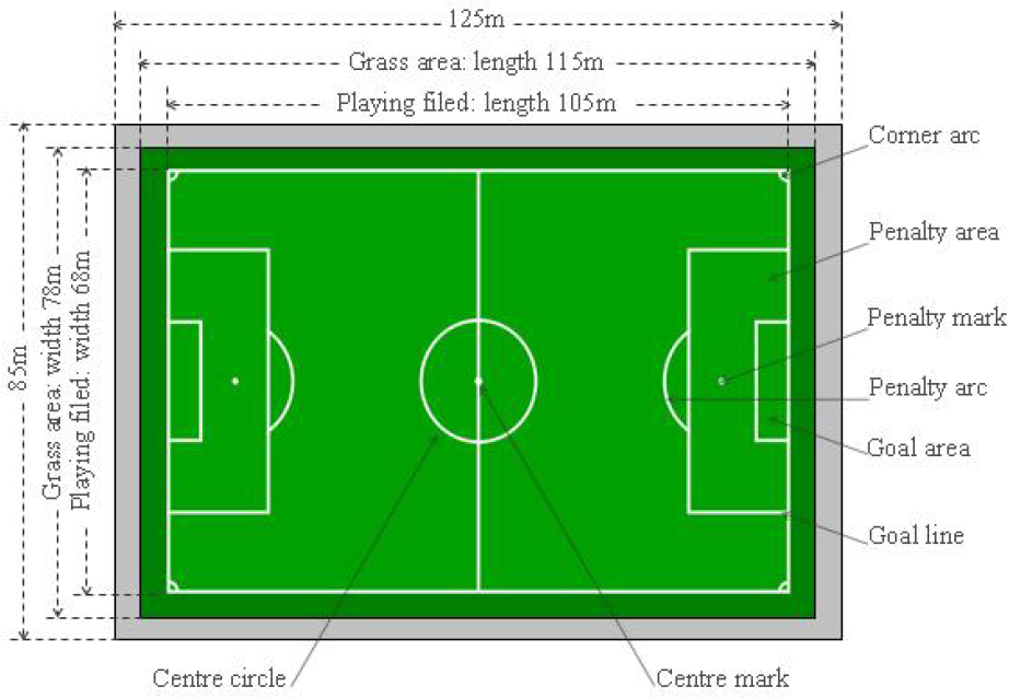
Dimensions of the playing field (FIFA, 2007).

Dimensions of penalty and goal area (left), central mark (up right) and corner arcs (bottom right) (FIFA, 2007).
3. A football's grass field representation
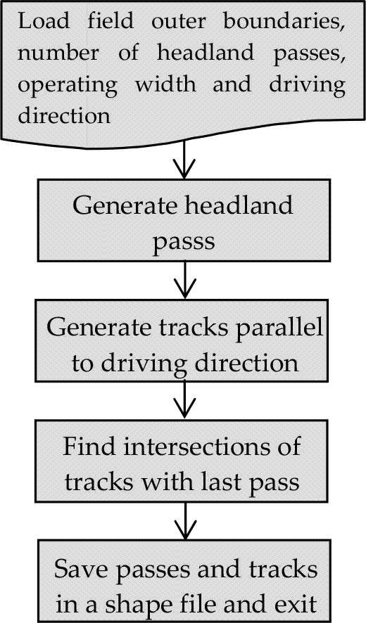
Three different tasks are required to be done in a football grass field, namely, grass cutting, lawn striping, and pitch and line marking illustration and hence three representations, one for each task, are required. For basic lawn striping patterns and if the required width of a lawn stripe is set equal to the operating width of the grass mower, grass cutting and lawn striping tasks could be done simultaneously by attaching a striping roller to the rare side of the mobile robot or the autonomous vehicle. For each individual task, a different driving course or what we call a field representation for guiding the vehicle through this specific task is obtained. A driving course is defined by a set of tracks or segments each is defined by a set of waypoints in 2D coordinates. The outer boundary of a grass field of a playing field is defined by a closed polygon (i.e., n vertices) represented in Universal Transverse Mercator (UTM) coordinate system in meters or in latitude/longitude coordinate systems in degrees. The vertices of the grass field outer boundary could be manually obtained by walking around the grass field and collecting enough number of points using a handheld GPS device or RTK-GPS device for better accuracy. It could also directly be obtained from shape files or from Google® maps. These coordinates are used as an input to the developed tool, along with, the operating width of the grass mower, the operating width of the lawn striping roller and the required striping pattern. The output will be three different driving courses, one for each task, represented as a set of way points in degrees (i.e., in latitude and longitude) stored in a KML file which is generally used to display geographic data in an earth browser such as Google maps®. The obtained KML file will be delivered to the vehicle computer control system in order to execute each individual task by the simple point-to-point driving. A general flowchart of the process used to generate these driving courses or task-based field representation is shown in Fig. 3. In the following sections, obtaining the way points for each driving course is explained in details.

Flow chart of in-football field operations.
3.1 Waypoints generation for grass cutting
According to the standards of the FIFA (FIFA, 2007), the grass area of a football field is defined as a rectangle of an area of 115×78 m2 but some grass fields have different shapes and different areas. The vertices of the outer boundary of the grass field could be given in the form of a shape file containing the outer boundaries of the grass field of the football stadium as a closed polygon in UTM coordinate system (i.e., in meters) or it could be obtained manually by collecting enough number of vertices to accurately represent the outer boundaries of the grass field in degrees using a handheld GPS device or RTK-GPS device for better accuracy. In case of manual collection of field vertices and since all calculations are done in meters, a conversion from latitude/longitude coordinate system (i.e., in degrees) into UTM coordinate system (i.e., in meters) is required. A tool for geometrical field representation for operational planning, developed by Hameed et al. (2010), is used to obtain the driving course for grass cutting operation. The inputs to the tool are the grass field outer boundary, the operating width of the robot or the autonomous vehicle used for grass cutting, the required driving direction and the number of headland passes. The tool allows for a driving direction defined by the angle between horizontal right-axis and the given line representing that direction. In this paper and for the sake of simplicity, the driving direction is defined as the line connecting any two different vertices of the grass field outer boundary. A flowchart showing the developing process of a driving course for grass cutting process is shown in Fig. 4.
Flow chart of developing a driving course for grass cutting operation.
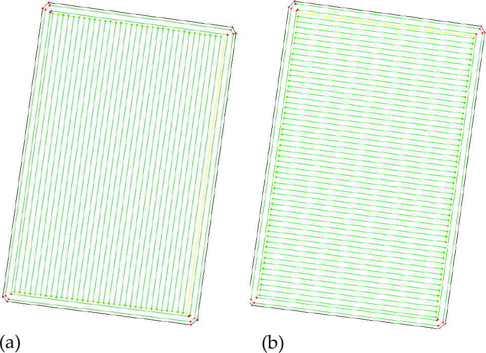
The developed tool reads the field's outer boundary from field shape file, the required number of headland passes, the driving direction and the operating width of the implement used for grass cutting (i.e., mower). The headland passes are generated by producing lines parallel to the field outer boundaries. Sharp edge and loop removal filters which remove possible sharp edges and possible loops in the generated headland pass are applied in order to produce smoother pass, see Fig. 5(a and b). The remaining field area, after the headland area, is then used for producing tracks parallel to the decided driving direction. The resultant waypoints are then saved in a shape file or KML file in order to be used by the robot or the autonomous vehicle for the automatic grass cutting operation. A good strategy to increase the life time of grass is to cut in different directions each time mowing is required and shift tracks a little in order to avoid tracks course by repeated passes. Fig. 6 shows the grass mowing process using 2 tracks in headland area and covering other field area by generating tracks parallel to the goal lines.

Filters applied to field headland passes in order to remove noises and irregularities for smoother headland passes: Sharp edge removal filter (a) and loop removal filter (b).

Basic grass cutting operation: 2 tracks in the headland area, d is the operating width of the mower implement/striping roller and driving direction is parallel to one of the field edges.
3.2 Waypoints generation for lawn striping
Intensifying lawn stripes to obtain different patterns is an optional step. Light and dark colored stripes are simply caused by light reflection off the blades of grass. It has not been cut at a different height nor is it a different breed of grass. The stripes are made by bending the blades of grass in different directions. The direction that the grass is bent determines the light or dark colored stripe. When the blades of grass are bent away from the viewer, the grass appears lighter in color because the light is reflecting off of the wide, lengthy part of the blade. When the blades of grass are bent towards the viewer, the grass appears darker as the viewer is looking more of the tips of the blades (a smaller reflective surface) and the shadows under the grass. So cutting a lawn in an opposing pattern (up/down, right/left, north/south, east/west etc) provides the most contrasting stripe effect. Interestingly, as the color of the stripe is dependent upon what direction the viewer is looking at it from, a light colored stripe will appear dark from the opposing direction. The easiest way to intensify the stripe is to bend the grass farther. The best way to do that is to physically contact the grass with a roller and press it to the ground. Some common stripe patterns, but not restricted to, are as follows (Scag Power Equipment, 2010):
Basic stripe pattern (BSP): tracks are generated parallel to one of the field sides, shown in Fig. 7. In this case, it is not required to intensify lawn stripes in a separate step if it is possible to attach the roller to the vehicle's three-point-linkage while grass is being mowed.
Checkerboard stripe pattern (CSP): this pattern is obtained by applying the stripes parallel to one side of the field and then in perpendicular direction (i.e., parallel to the other side of the field), shown in Fig. 8.
Diagonal stripe patterns (DSP): this pattern is achieved using the same techniques as the CSP listed above. Simply apply the stripes in a diagonal direction, shown in Fig. 9.

Baisc lawn stripe pattern (Scag Power Equipment, 2010).
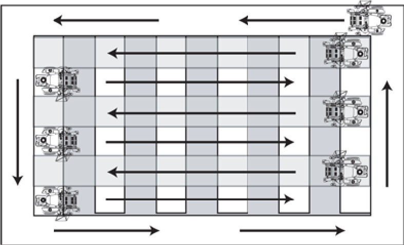
Checkerboard stripe pattern (Scag Power Equipment, 2010).
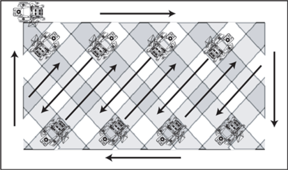
Diagonal stripe pattern (Scag Power Equipment, 2010).
Other patterns could be easily designed and obtained. The waypoints for these patterns are generated by using the automatic route planning algorithm described in Section 3.1 by selecting the appropriate driving direction to generate each specific pattern.
3.3 Pitch and line marking illustration algorithm
In this section, the algorithm for generating waypoints for the vehicle to navigate through the field for pitch and line marking illustrations is introduced. The input to the algorithm is the UTM coordinates of the grass field outer boundaries. The outputs are the vertices of the playing field, penalty area, goal area, central mark and corner arcs in UTM coordinate system. The coordinates are then converted into degrees and saved in a KML file for navigation.
According to standards of FIFA, the playing field is a rectangle of length l p = 105 m and width w p = 68 m. The dimensions for the center circle and penalty kick arcs are measured from the center of the field and penalty spot respectively, to the outside of the lines. The radii of corner arcs are 1 m and the radii of the center circle and goal circle are 9.15 m. The inside faces of the goal-posts should be 7.32 m apart and the distance between the ground and the underside of the crossbar is 2.44 m. The width of the playing lines should be 120 mm maximum and the goal-line should be marked the same width as the depth of the goal posts which should be considered in the design of the pitch and track marking implement. Line color is not specified but is traditionally white. The external dimensions should include the width of the lines. The center of the penalty spot is measured from the outside of the goal line. The UTM coordinates of the playing field for pitch and line marking illustrations are obtained as follows.
Boundaries of the playing field The dimensions of a playing field, according to standards of FIFA, are 105×68 m2, as shown in Fig. 1. In order to obtain the UTM coordinates of the four corner points (i.e., vertices) of the rectangle-shaped playing field, if the grass field is rectangle, the grass field is de-expanded by distance r m, given by Eq. (1) where l g , w g are the length and width of the grass field, respectively, and l p , w p are the length and width of the playing field, respectively.

If the grass field is not a rectangle, it must be rectanglized first by finding the intersection points between each touch (i.e., longest edge of the playing field) and goal (i.e., shortest side of the playing field) lines and repeating this process until we obtain the four vertices of the rectangle-shaped playing field. The de-expanded field is obtained by applying the automatic route planning algorithm described in Section 3.1 as the process of obtaining a headland pass.
Center line
Center line is the line connecting the two center points located exactly at the middle of each of the two opposite touch lines. A center point is obtained by finding the UTM coordinates of the point dividing the touch line by two (i.e., l p /2).
Center mark
Center mark is the point located exactly at the middle of the center line. It is obtained by finding the UTM coordinates of the point located on the center line and dividing it by two. The center mark is illustrated by a circle of 0.15 m radius.
Center circle
The center circle is illustrated by a circle of 9.15m radius centered at the center mark with a line of 0.12 m thickness.
Penalty area
Penalty area is the area bounded by the penalty lines forming a rectangle of area of 40.32×16.5 m2. There are two opposing penalty areas in the field, each consists of penalty lines, penalty mark and penalty arc.
Penalty lines
There are three penalty lines; one line, of length 40.32 m, parallel to the goal line and two parallel lines, of length 16.5 m, perpendicular to the goal line and at distance of 40.32 m from each other. The two vertices of the perpendicular penalty lines are located on the goal line at distance of (68-40.32)/2 m and (68+40.32)/2 m from each end of the goal line, respectively. The other two vertices are located at the parallel penalty line and at distances of (68-40.32)/2 m and (68+40.32)/2 m from each end of the parallel penalty line, respectively. The parallel penalty line is the line parallel to the goal line and at distance of 16.5m from it.
Penalty mark
Penalty mark is a circle of 0.15 m radius centered at a point located at distance of 11 m from the end point of a line parallel to the touch line (i.e., longest edge of the playing field) and at the center (i.e., at distance of 68/2 m from the touch line) of the side line.
Penalty arc
Penalty arc is an arc of a circle of radius 9.15 m centered at the penalty mark.
Goal area
Goal area is the area bounded by the goal lines (forming a rectangle of area 18.32×5.5 m2). Goal lines are three; one of length 18.32 m parallel to the goal line and two of length 5.5 m perpendicular to the goal line. The UTM coordinates of the vertices of this rectangle are obtained by allocating two points on the goal line at distances of (68-18.32)/2 m and (68+18.32)/2 m from each of its ending points. The other two vertices are allocated on the line parallel to goal line (i.e., the short side of the playing field) at distance of 5.5 m and at distance of (68-18.32)/2 m and (68+18.32)/2 m from each of its ending points.
Corner arcs
There are four corner arcs in the field located at each corner point of the playing field with radius of 1 m.
A computer program to generate the above vertices has been developed using Matlab® programming language and it is available for free for interested readers by contacting the corresponding author.
4. Economic feasibility study
In this section, the costs of the manual practices of the above operations are investigated. As an example, in Viborg football stadium, Stadion Alle 1–3, 8800 Viborg, Denmark (http://viborg.dk/stadion), grass mowing, intensifying lawn stripes and pitch and line marking illustrations cost from 40 to 50 working hours per week. One working hour costs on average 350.0 Danish Krone so totally 672,000.0 to 840,000.0 Danish Krone (1.0 Danish krone = 0.18 USD) per year. In addition, new workers require especial and expensive training which is not considered here. Using the developed system, stadiums will invest only in machines and it will be able to save extra working hours and cost of training new employs. The developed system will allow a worker to focus on other works, save time and able to work 24 hours/7 days per week.
5. Simulation results
In this section, the developed algorithms are successfully applied to several international and national football stadiums in Denmark and the world. Due to the limited space and to avoid repeatability, the resultant waypoints of applying the developed algorithms to Viborg Stadium, Stadion Alle 1–3, 8800 Viborg, Denmark, will only be introduced. The latitude/ longitude coordinates (in degrees) of the outer boundaries of the grass field of Viborg Stadium is shown in Table1. A satellite image of Viborg Stadium, Stadion Alle 1–3, 8800 Viborg, Denmark, is shown in Fig. 10.

Satellite image of Viborg Stadium (Stadion Alle 1-3, 8800 Viborg, Denmark).
The UTM coordinates of the grass field of Viborg football stadium.
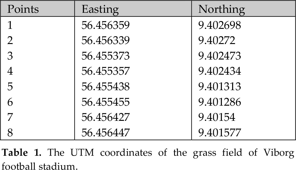
The grass field of Viborg stadium is not rectangular and therefore it is described by eight vertices. Two different driving courses can be followed by the autonomous vehicle or the robot in its point-to-point motion in order to cut the grass field; the first driving course is obtained by driving parallel to the touch line of the grass field (i.e, parallel to the longest side of the grass field) while the second driving course is obtained by driving parallel to the side line of the grass field (i.e., perpendicular to the touch line of the grass field or parallel to the goal line). The resultant driving courses for a grass mowing implement of 2 m working width are shown in Fig. 11. Basic lawn striping patterns can be easily obtained by combining a striping roller with a grass mower and by using the same driving courses shown in Fig. 11. Checkerboard striping pattern is obtained by driving parallel and then perpendicular to the longest side of the grass field, while, the diagonal striping pattern is obtained by driving parallel and then perpendicular to diagonal of the grass field, as it is shown in Fig. 12(a) and (b), respectively, for a striping roller of 2 m operating width. The way points of these striping patterns can be saved into KML files which can be easily used for the auto-steering of the autonomous vehicle or simply for visualizing the resultant driving course on Google maps as it is shown in Fig. 13 (a) and (b) for the checkerboard and diagonal striping patterns, respectively. The course for pitch and line marking illustrations is shown in Fig. 14(a) for the waypoints in UTM coordinate system (i.e., in meters) and in Fig. 14(b) for the waypoints converted into lat/lon coordinate system (i.e., in degrees) and stored in a KML file for the easily representation of the resultant on Google maps.
Way points for mowing Grass field of Viborg Stadium and the classical stripe pattern in two different driving directions.

(a) Checkerboard stripe pattern, and (b) diagonal stripe pattern of Viborg stadium.
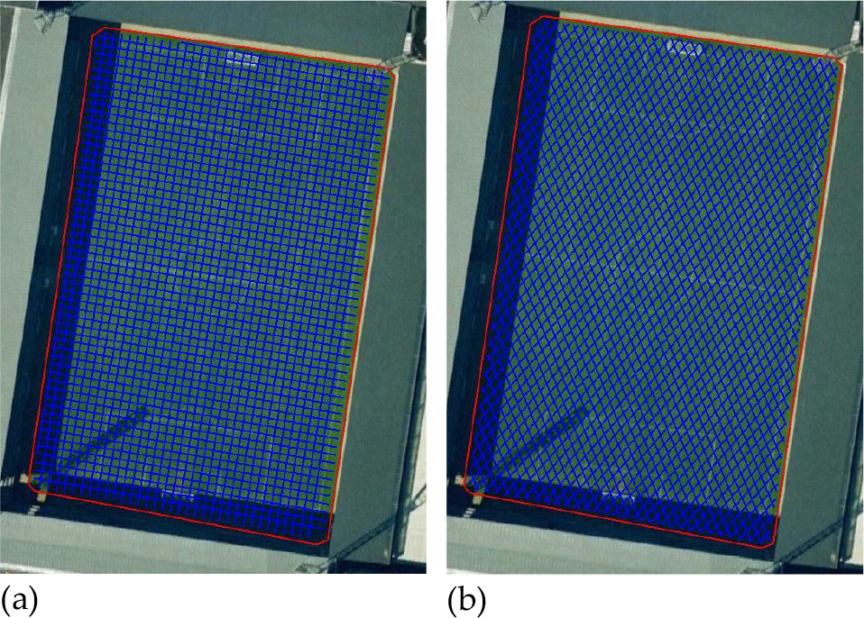
(a) Checkerboard stripe pattern, and (b) diagonal stripe pattern of Viborg stadium.
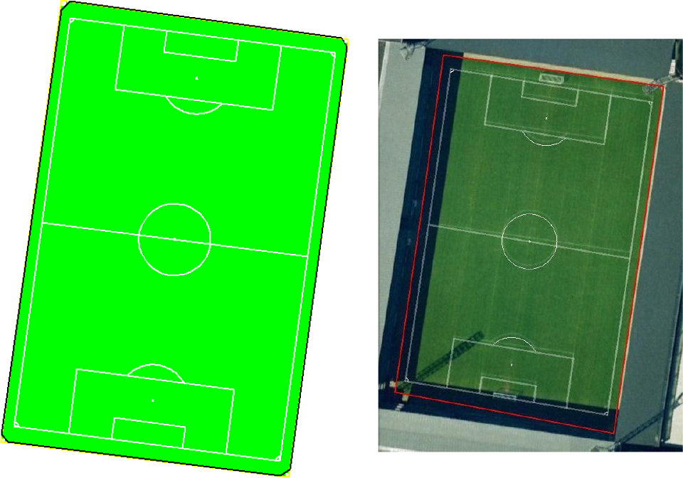
Pitch and line marking illustrations of Viborg Stadium operated using the algorithm: (a) waypoints in meters, (b) a KML file of waypoints in degrees.
Simulation results showed that the proposed method is able to automatically provide waypoints with very high accuracy without exhausting on-ground measurements. For the current GPS-guided autonomous vehicles, the navigation accuracy on a straight line motion is approximately ±2 cm. it has been proved that the system can perform better under good conditions and terrain (Keicher and Seufert, 2000). When the proposed method applied to other stadiums, it was able to detect that some stadiums such as the Danish National Stadium and the Egyptian army stadium are not compatible with the dimensions approved by FIFA for international games.
6. Conclusions
The developed tool provides simple algorithms able to automatically carry out the periodical operations which are used to be done manually in regular bases in football stadiums. These operations require very high qualified and expensive personnel who have to keep very high concentration during these operations in order to match the standards set by the FIFA. The developed tool provides the waypoints for each operation in meters and in degrees and store it in a standard KML files to be later used by the vehicle computer control system for navigation. The developed approach is not limited to football playing fields but can also be used for other games such as hockey, tennis, etc. It also can operate playing fields of different sizes and produce very complex lawn striping patterns with no human intervention and with very high accuracy. The tool is implemented using Matlab® from Mathworks™ and is available for free for interested readers.
Footnotes
Acknowledgements
The authors are gratefully acknowledging Mr. Torben Simonsen, Viborg stadium, 8800 Viborg, Denmark and the constructive comments of anonymous referees.