
Abstract
Hollow fiber bioreactors are the focus of scientific research aiming to mimic physiological vascular networks and engineer organs and tissues in vitro. The reason for this lies in the interesting features of this bioreactor type, including excellent mass transport properties. Indeed, hollow fiber bioreactors allow limitations to be overcome in nutrient transport by diffusion, which is often an obstacle to engineer sizable constructs in vitro. This work reviews the existing literature relevant to hollow fiber bioreactors in organ and tissue engineering applications. To this purpose, we first classify the hollow fiber bioreactors into 2 categories: cylindrical and rectangular. For each category, we summarize their main applications both at the tissue and at the organ level, focusing on experimental models and computational studies as predictive tools for designing innovative, dynamic culture systems. Finally, we discuss future perspectives on hollow fiber bioreactors as in vitro models for tissue and organ engineering applications.
Keywords
Introduction
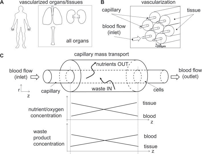
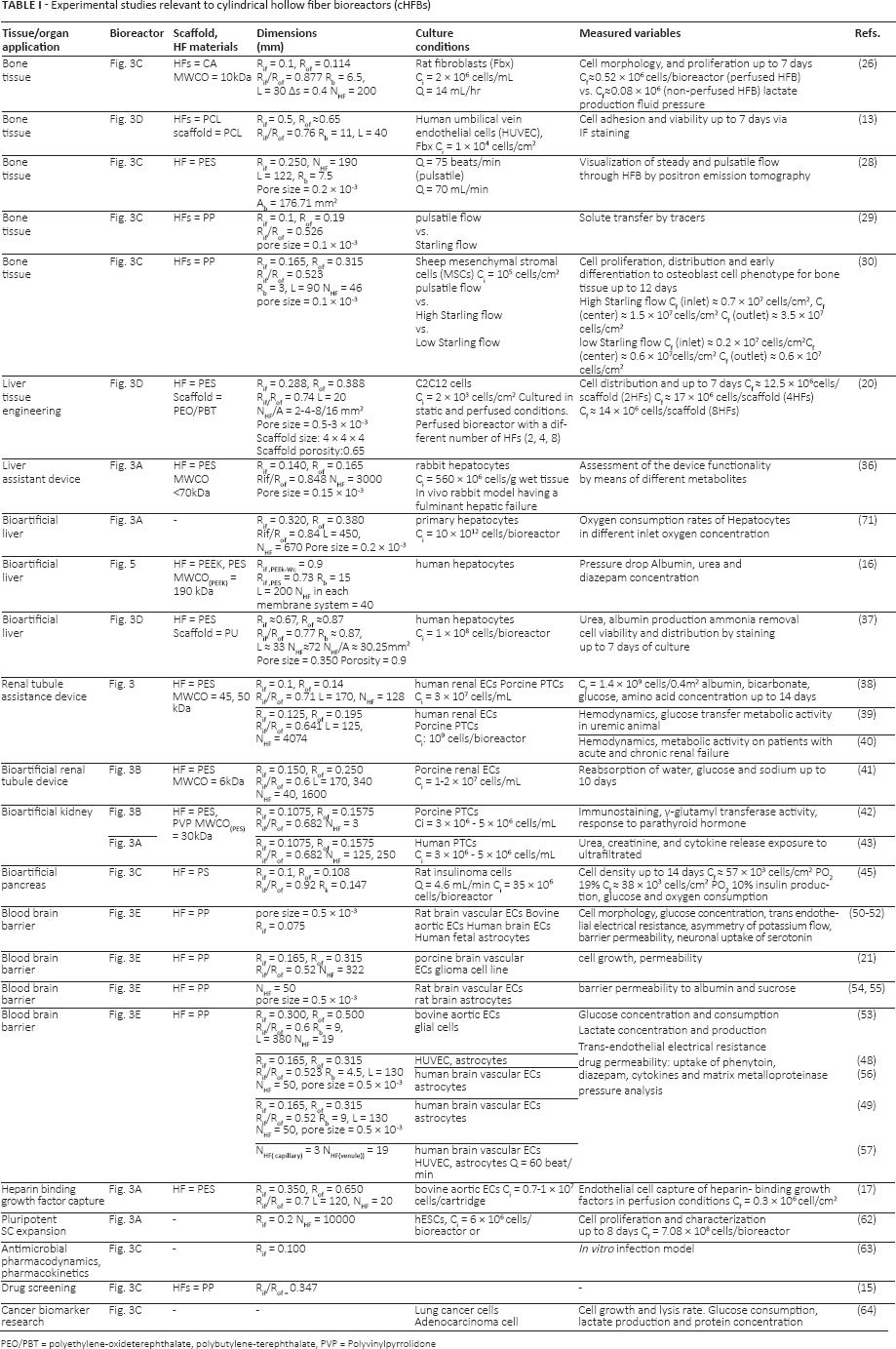
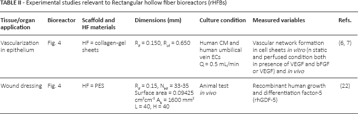
All organs in the body have a vasculature network whose main function is to maintain homeostatic conditions in the tissue for optimal function and survival of the cells (Fig. 1A). Thanks to the hierarchical architecture of the circulation system, blood vessels enable the distribution of energy in the body, the transportation of different nutrient or signal molecules and the removal of waste products arising from the cell metabolism (Fig. 1B, C). To ensure viability in vivo, cells are generally immersed in a three-dimensional (3D) environment and located no more than approximately 100 to 200 μm from microvessels or capillaries, which supply them with oxygen and nutrients.
Scheme of native tissue vascularization. (
It has been reported that the cell region beyond a 100-μm thick layer cannot be supported in vitro via diffusion under static conditions (1). The diffusive mass transport limits the size of engineered 3D organs and tissues. Therefore, dynamic culture systems or bioreactors for large tissue defects need to be designed in such a way as to avoid hypoxic and necrotic conditions and may require a complex vascular network to deliver nutrients and oxygen to cells (1).
To overcome the nutrient diffusion limit for tissue/organ engineering applications, hollow fiber bioreactors (HFBs) were designed with the aim of mimicking the native vasculature in living tissues. HFB geometry offers a series of benefits, including compactness, a large mass exchange surface area to bioreactor volume ratio around 30 cm2/cm3. HFBs have excellent mass transfer properties and provide cell protection from mechanical stresses. Other advantages rely on the virtual absence of the cell wash out, the ability for the immune isolation of xenogeneic cells and the possibility for scaffolding the cells with membranes (2–4).
Here, we review the existing literature on HFBs from an engineering standpoint. To this purpose, we classified HFBs into 2 main categories: cylindrical hollow fiber bioreactors (cHFBs) and rectangular hollow fiber bioreactors (rHFBs). For each group, we report on the main design and operating parameters as well as on their main applications at the tissue/organ level, focusing on the experimental and computational outcomes. Finally, we critically discuss the perspectives of HFBs as in vitro models for vascularized tissue and organ engineering.
Hollow fiber bioreactor configurations
Several HFB configurations have been proposed for organ and tissue engineering. We classified HFBs into 2 main categories according to the mass exchange surface area to bioreactor volume ratio and the modularity of such systems. In cHFBs, the surface to volume ratio is higher if compared to its counterpart in rHFBs. Rectangular HFBs, on the contrary, might be more suitable for a potential subcutaneous implantation due to their limited hindrance/size, whereas cHFBs may be more suitable as external support systems. In terms of modularity, rHFBs may be designed by small, cell-laden modules (i.e., building blocks) to be assembled into larger constructs. This bottom-up approach makes it possible to mimic the heterogeneity of the culture environment and the complexity of some organs that have repetitive modules (5–7). According to the above-mentioned criteria, we grouped HFBs into cHFBs and rHFBs. Examples of the use of these 2 configurations are presented in Tables I and II, respectively.
Experimental studies relevant to cylindrical hollow fiber bioreactors (cHFBs)
PEO/PBT = polyethylene-oxideterephthalate, polybutylene-terephthalate, PVP = Polyvinylpyrrolidone
Experimental studies relevant to Rectangular hollow fiber bioreactors (rHFBs)
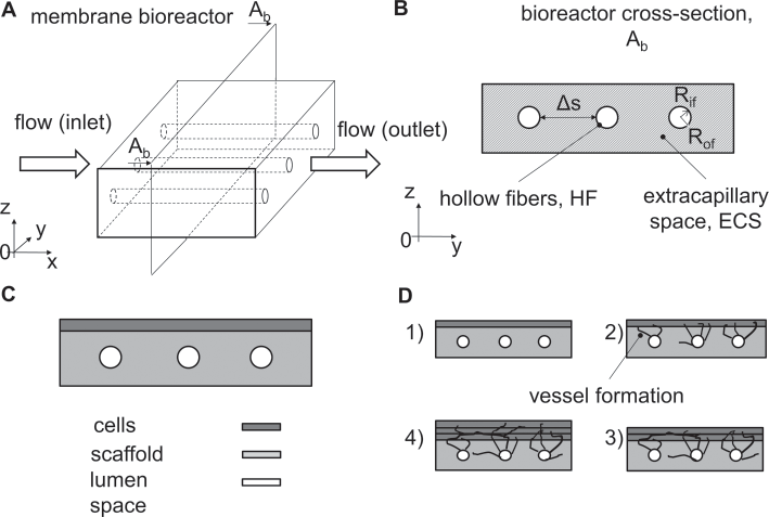
Cylindrical HFBs are composed of a bundle of parallel, semipermeable, hollow fibers (HFs) assembled in a cylindrical housing or in a cartridge. Cylindrical HFBs have a specific versatility due to multiple possible paths for the medium flow and cell location. The medium may flow through HFs and/or through the extracapillary space (ECS) (Fig. 2A). In Figure 2B, we show the cross-section view of the bioreactor Ab, and the localization of the HFs, whose size (e.g., inner radius Rif, outer radius Rof), number NHF, fiber interdistance δs, and arrangement may vary according to the tissue/organ application (Fig. 2C).
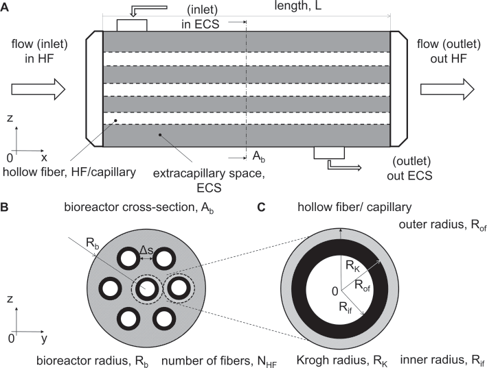
Sketch of a hollow fiber bioreactor (HFB). (
Concerning cell location, the cells can be directly seeded on the outer surface (Fig. 3A) or in the internal lumen (Fig. 3B) of the HFs, while the medium flows in the internal HF lumen. The nutrient transport depends on the ratio between the convective transport in the liquid phase and the diffusion through the HF to cells (Fig. 3A). Conversely, as shown in Figure 3B, cells can be directly exposed to the culture medium. In such a configuration, cells are subjected to shear stresses, while nutrients are provided mostly by convective transport. In further configurations, cells can be cultured in a gel (Fig. 3C) or in a porous scaffold (Fig. 3D) filling the ECS, while perfusion occurs in the HF lumen. Finally, cells can be cultured both on the internal and/ or the external surface of the HFs (Fig. 3E).
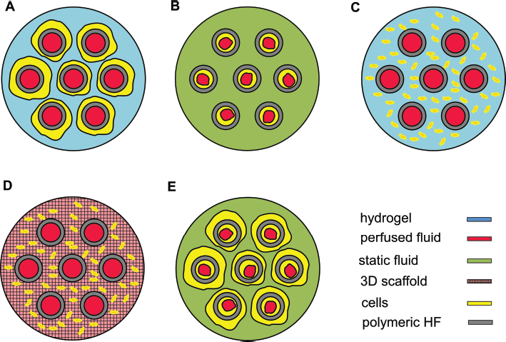
Configurations of cHFBs according to the cell location. The cells can be cultured on (
For example, in many cHFB applications, cells were cultured in a gel in the ECS while the culture medium flows in the HFs. This kind of operating cHFB was used in particular to engineer bone and cartilage tissues (3, 8–14), for drug screening (15) and testing (4) (Fig. 3A, C, D). Concerning liver engineering, cells were cultured on the external surface of the HFs and the culture medium flowed in the lumen (16, 17) (Fig. 3A). Regarding other cHFB applications such as hemopurification (18) and a bioartificial kidney (19), a 2-fluid flow system was designed with cells cultured in the inner surface of HFs (Fig. 3B). In bone (13), liver and for muscle tissue engineering (20), several applications were based on the use of 3D polymeric scaffolds in the ECS of cHFBs (Fig. 3D). Finally, cHFB configurations allowed the culturing of 2 types of cells physically separated by the HFs (Fig. 3E), for example, in blood brain barrier (BBB) bioreactors (21).
Rectangular HFBs are composed of a hollow fiber membrane embedded within a scaffold with a rectangular shape (Fig. 4A). As shown in the cross-section view Ab of the rHFB (Fig. 4B), the localization of HFs, as well as their size (e.g. the inner radius Rif, the outer radius Rof), number and inter-distance δs, may vary according to the tissue/organ application. In this configuration, the medium flows through the HFs internal lumen and one or more cell sheets can be cultured on the top of the polymeric hollow fiber membrane scaffold (Fig. 4C, D). This configuration was used to model wound repair in vivo (22) and the angiogenesis occurring in cardiac tissue both in vitro and in vivo (6, 7).
Rectangular hollow fiber bioreactors. (
Hollow fiber fabrication and characterization
Hollow fibers can be fabricated by extrusion or wet phase inversion spinning techniques (23). Wet phase inversion spinning is the most widely used technique to fabricate HFs for the purposes of bioartificial organs and tissue engineering. Other HF manufacturing techniques include electrospinning and dip coating methods (23).
The HF fabrication parameters affect their mechanical and transport properties, including pore morphology and permeability (23). Actually, HF pore morphology and size act as a selective barrier for molecules that have a steric hindrance larger than a given pore dimension. The membranes are classified according to molecular weight cutoff (MWCO), which is defined as the molecular weight of the species that is 90 percent retained by the membrane (24). According to the manufacturing process, the HF MWCO ranges from of 6 to 190 kDa (Tab. I). The MWCO parameter is commonly used to design immune selective barriers to prevent the passage of immune-competent species (24). Concerning the material types, several synthetic polymers were used both in the cHFB (Tab. I) and in the rHFB (Tab. II) configurations. The employed polymers in cHFBs were polyethersulfone (PES), cellulose acetate (CA), poly(lactic-co-glycolic acid) (PGLA), polypropylene (PP), poly(ε-caprolactone) (PCL) for bone tissue engineering applications. In addition, polysulfone (PSF) and PES were employed to manufacture HFs for bioartificial liver, kidney and pancreas devices. Finally, PP was used for BBB and other applications, including drug screening (Tab. I). All these materials can be processed alone or in blends for HF fabrication. However, polymer blending may enhance the HF mechanical properties, the degradation rate and the hydrophobicity/hydrophilicity for specific applications. In the rHFB configuration, HFs were manufactured by using PES embedded in collagen gels as a biodegradable polymer or scaffolding material (Tab. II).
Design and operating parameters of hollow fiber bioreactors
The design and the optimization of the operating parameters in the HFBs are crucial to increase the ability to mimic the in vivo environment in bioreactor cultures. These parameters include the HFB geometry (e.g., the inner and outer HF radii Rf and Rof, the interfiber spacing δs, the bioreactor radius Rb, and length L) (Fig. 2). Moreover, the medium culture flow parameters need to be carefully optimized. For example the flow regime (i.e., steady or pulsatile), the perfusion rate and the fluid properties. The HF porous membrane parameters, including the porosity, the pore size, the hindrance factor, the MWCO, the permeability and the membrane physicochemical properties, affect the bioreactor performance as well. Finally, mass transport parameters relevant to oxygen, nutrients and waste species as well as the culture conditions (e.g., the cell type, the cell passage and the cell-seeding density) are other important operating parameters in HFB cultures to be considered. On the basis of the existing literature, the laminar flow regime was extensively adopted in experimental studies due to the low shear stresses exerted on cells. This allows the cell wash out from the culture substrate to be prevented (Tabs. I and II).
Cylindrical hollow fiber bioreactors for tissue and organ engineering
Three-dimensional tissues
Natural tissues, such as bone tissue, are highly vascularized. Although viable large-tissue bone grafts of several millimeters can be obtained in perfused bioreactors, several limitations need to be overcome. In particular, an adequate mass transport to the cells, especially those cells embedded in the middle of the constructs (25). Under diffusion-limited culture conditions, the size of engineered viable bone tissues is less than 0.5 mm thick due to the mass exchange of nutrients and oxygen, which takes place solely by molecular diffusion (26, 27). To overcome nutrient diffusion limitations, biological angiogenesis is the primary requirement to generate dense tissues. However, angiogenesis remains a technical challenge in tissue engineering (9). Within this context, HFBs were designed to mimic the native blood capillary system in the aim to enhance the molecule transport and mass exchange between the fluid (i.e., medium) and the cell phase by introducing a velocity flow field (i.e., convective term). Such systems are illustrated in Figure 3C, D.
In the realm of bone tissue engineering, the use of cHFBs was widely investigated. For example, Ye and colleagues (26) proposed a cHFB configuration like the one shown in Figure 3C. It was demonstrated that such cHFB layouts induced significantly greater cell viability, proliferation and a more bone-like cellular morphology when compared to constructs cultured under nonperfused conditions (Tab. I).
Hadjizadeh's group introduced an innovative scaffold for cHFB for growing bone and viable tissue constructs on a laboratory scale. The form of this scaffold consisted of a sheet with parallel channels that could either be rolled to fit a cHFB cartridge by maintaining parallel hollow fibers, or kept in a flat, rectangular membrane to be used as an rHFB (13) (Fig. 3D). In this configuration, the polymeric scaffold and the HFs were fabricated in the same material (PCL). The cell adhesion and viability tests showed that this configuration possessed good potential for the engineering of large-scale, vascularized tissue constructs (Tab. I). In cHFB cartridges (Fig. 2C), positron emission tomography (PET) was used as a noninvasive method for the fluid flow visualization. It was observed that the spatial distribution of the fluid streamlines was more homogeneous under pulsatile condition (75 beat/ min) if compared to the steady laminar flow condition (Q = 70 mL/min) (28) (Tab. I).
The effect of the perfusion regime (i.e., pulsatile and Starling low to high) on solute transfer and cell viability and distribution in cHFBs having a configuration shown in Figure 3C were also investigated. After 12 days of culture at high Starling flow, a homogeneous cell density restricted to a region of dimensions of about 2.5 cm in length and 0.6 cm in diameter in engineered bone constructs was observed. The rest of the cellularized scaffold of an overall length L = 9 cm, has shown a less homogeneous cell density, far from the natural bone (29, 30).
To overcome the limitations of nutrient diffusion in large 3D tissue constructs, a novel HFB integrated with a 3D polymeric macroscopic porous scaffold (pore size = 500 μm) in the configuration shown in Figure 3D was reported. Mouse premyoblasts (C2C12) were investigated both under static and dynamic conditions with a different number of HFs (2, 4 and 8) embedded in constant-volume, polymeric, porous scaffolds. It was demonstrated that cell homogeneity and proliferation in the cHFB with 4 HFs was significantly greater compared to the other configurations. In the cHFB with 8 HFs, the seeding efficiency and the cell proliferation decreased due to a reduction in the available space in the porous scaffold. In the cHFB with 2 HFs, despite the greater available space for cells to grow, the distance between fibers As, and therefore the relatively high characteristic diffusion length of nutrients, affected cell viability and proliferation (20) (Tab. I).
Bioartificial organs
HFBs were largely used as bioartificial organs (BAOs) with the aim of temporarily supporting, or potentially substituting/ replacing vital organ functions of the malfunctioning liver, kidney and pancreas. In such applications, HFs should not be biodegradable and should support cell adhesion as a scaffold. Moreover, on the one hand, HFs have to act as an immunoisolation barrier, but on the other hand, they have to allow mass exchange between the fluid and the cell phase. Hence, the pore size of the HF membranes must be small enough to isolate the embedded exogenous cells but sufficiently large to allow appropriate mass transfer of nutrients to cells and removal of waste metabolites (23, 31–34).
Concerning liver tissue engineering, cHFBs configured as in Figure 3A were widely investigated. Such bioreactors aimed at increasing the oxygen supply to the hepatocytes and enhancing their proliferation and metabolic activity. Liver cells were cultured as aggregates in the ECS or on the HF outer surface, while the medium (e.g., blood, plasma or medium) flowed in the HF internal lumen (35). The functionality of such devices was demonstrated in an in vivo rabbit model with fulminant hepatic failure (36).
Regarding cHFB bioartificial liver (BAL) applications, a further configuration was investigated (Fig. 3D). The device was composed of a 3D polymeric scaffold (i.e., PL) foam) integrated with HFs. In this system, cells were cultured both in the ECS and on the outer HF surfaces (Fig. 3D). In this in vitro study, the authors have shown that this cHFB allowed better mass transfer, improved cell distribution and liver-specific functions of hepatocytes when compared to an ordinary HFB without the polymeric scaffold (37) (Tab. I).
Finally, a new design for BAL consisting of a crossed HFB was developed (16). The culture system was composed of PolyEtherEtherKetone (PEEK)-HFs and PES-HFs in an alternating manner. These 2 HF types had different MWCO, physicochemical and permeability properties. The PEEK-HFs provided cells with an oxygenated medium containing nutrients and metabolites, whereas the PES-HFs removed catabolites from cell compartments, mimicking the in vivo hepatic perfusion (Fig. 5). This new layout has shown good results in terms of hepatic functions (i.e., concentrations of albumin, urea and diazepam).
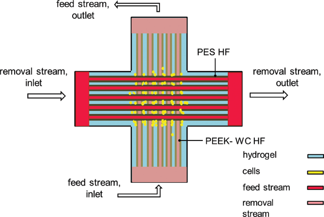
Top view of the crossed HF membrane bioreactor (described in ref. 16). Nutrients flow in PEEK-WC HFs lumen while a fluid flow for waste removal flows in PES HFs lumen. Cells are cultured in the extraluminal compartment.
Concerning renal assist devices (RADs), several efforts were made with the aim of designing devices to support/replace kidney functionalities. Humes et al presented the first concept of using HFs for renal cells in 1999 (38, 39). Porcine renal proximal tubule cells (PTCs) were cultured on the inner surface side of a single HF. In a further work, they scaled up this single HF to a cHFB system where cells were still cultured in the intraluminal space of the HF. The intraluminal space was perfused with culture medium, while the ECS was filled with culture medium (i.e., no perfusion) (Fig. 3B). They measured the mass transport and metabolic parameters, including albumin, bicarbonate, glucose and amino acids. Notably, the cell construct showed active transport capabilities (i.e., reabsorption and secretory capabilities) and enhanced cell metabolic activity (18). They also tested this cHFB (Fig. 3B) as a kidney support system on animals and human patients with acute and chronic renal failure. They demonstrated improved metabolic performance and significant systemic effects induced by the device. However, due to safety reasons, this application had to be discontinued after 24 hours (40) (Tab. I). Ozgen et al succeeded for the first time in using a cHFB configured like the one described above (Fig. 3B) to achieve some key functionalities of the kidney, such as the absorption of water, glucose and sodium in long-term culture (i.e., up to 10 days) (41) (Tab. I). Oo et al used human PTCs in a cHFB arranged with 3 HFs (Fig. 3B). The results have shown that under perfusion conditions, human PTCs formed a functional epithelium in optimized double-coated HFs. (42) (Tab. I). In another work by the same group, a novel cHFB design of the bioartificial kidney application was presented (Fig. 3A). Human primary renal PTCs were cultured on the outer surface of the HFs to increase PES hemocompatibility. By this method, the authors showed that no HF coatings were required to obtain a robust and functional renal epithelium. They also demonstrated that this bioreactor was able to produce significant amounts of interleukins, known as immunomodulatory molecules (43) (Tab. I). However, many limitations still need to be overcome before clinical applications can be made of such constructs, including low metabolic, endocrine and immunomodulatory renal cell functions.
Concerning bioartificial pancreas devices, these systems can be designed as extravascular and intravascular devices, as well as microencapsulated Langerhans islets (3, 44). In such devices, HFs have to be conceived as an immunoisolation barrier to both protect the transplanted Langerhans islets from the host rejection (i.e., acting as a barrier to immunoglobulins and other inflammatory molecules) and to allow nutrients, glucose and insulin to pass through the membrane towards cells. In this work, we are referring to the bioartificial pancreas in the cHFB configuration. For example, Gundersen et al theoretically and experimentally investigated the effect of oxygen concentration on expansion of rat insulinoma cells and their ability to generate insulinin within a cHFB (Fig. 3C). The authors have shown that the HFB oxygenation did not affect glucose and oxygen consumption. Moreover, it was possible for insulinoma cells to be expanded and insulin production to be enhanced (45) (Tab. I).
The blood brain barrier
The blood brain barrier (BBB) presents a highly selective permeability barrier that separates the circulating blood from the brain extracellular fluid in the central nervous system. The blood brain barrier allows the passage of water, gases and lipid-soluble molecules by passive diffusion as well as the selective transport of molecules such as glucose and amino acids that are crucial to neural function (46, 47) (Tab. I).
Most in vitro BBB models proposed were based on co-cultures of brain endothelial cells and astrocytes (or glial cells) cultured under static conditions. Besides co-culturing cells in static systems composed of 2 chambers (47), dynamic in vitro blood brain barrier (DIV-BBB) models were developed both as cHFBs and as microfluidic devices. Here we focus on cHFBs employed as DIV-BBB devices. Such devices consisted of a cylindrical shell embedding HFs in which endothelial cells were cultured on the inner surface of the HFs while astrocytes and/ or pericytes were localized on the outer surface. The medium was flowed in the intraluminal space in laminar or pulsatile regime (Fig. 3E).
For example, DIV-BBBs were demonstrated to be a more powerful alternative to static in vitro BBB models because of their ability to recapitulate some features of both the physiologic and nonphysiologic permeability properties of the BBB in vivo (48, 49) (Tab. I). A possible reason resides on the velocity field and the relevant shear stress field acting on cells that are able to better mimic the local physiological brain microenvironment (50–55). The morphology of cultured cells, the cell glucose consumption, the lactate production, the transendothelial electrical resistance in HFs and other parameters, including the potassium transport and the HF permeability to drugs, were investigated.
To better mimic the physiological BBB, a further degree of complexity in DIV-BBB design was introduced. For example, to study the physiological and functional behavior of distinct segments of the human cerebrovascular network, a novel capillary-venule modular system composed of a combination of 2 DIV-BBBs was presented (56, 57). Both the venule and the capillary module were configured as cHFBs. In the venule module, ECs and human brain vascular smooth muscle cells (SMCs) were cultured on the inner and outer surfaces of the HFs, respectively. On the other hand, human primary brain microvascular endothelial cells (ECs) were co-cultured with human astrocytes on the outer surface of the HFs, in the capillary module. A pulsatile flow was imposed to better mimic the fluid dynamic conditions in vivo. It was shown that ECs exposed to shear stress and fluid pressure had a comparable morphology and functionality with respect to their in vivo counterparts (56, 57). Thus, DIV-BBB models may be used to further investigate in vitro the immune cell trafficking across the BBB (Tab. I) A further field of research resides in pharmaceutical drug screening and discovery (58, 59) to reduce laboratory tests on animals (60, 61) (Tab. I).
Rectangular hollow fiber bioreactors (rHFBs)
The rectangular HFB is a newly introduced approach in the field of HFBs (Fig. 4). This configuration is oriented towards the implantation of bioreactor-generated tissues for therapeutic applications. Pletting et al reported a novel active wound dressing (AWD) based on HF membranes in a porcine wound model (22) (Tab. II). The rHFB was similar to the one shown in Figure 4B. A device of this sort was able to create a local medium-perfused environment, which enabled adequate moisture levels in the wound. This is crucial for skin regeneration without scar tissue formation. Sakaguchi et al presented a new strategy to design vascularized 3D tissues using HFs. The device consisted of HFs embedded in collagen gel sheets (Fig. 4C). Cells cultured on the top of such sheets exhibited significant viability due to molecular diffusion through the collagen scaffold, and, interestingly, spontaneous angiogenesis was observed by cultivation of cell layers up to 20 days (Fig. 4D) (6, 7).
Other applications of HFBs
Besides organ and tissue applications, HFBs have been designed for other purposes. Pluripotent stem cells such as embryonic stem cells are a source for the production of different cell types. HFBs are promising tools to scale up stem cell production to provide adequate cell numbers. For example, Roberts and colleagues used a cHFB (Fig. 3A) in a pilot study to expand human embryonic stem cells. They could expand 60 million human embryonic stem cells up to 708 million cells during 8 days while maintaining their pluripotent phenotype and differentiation potential (62) (Tab. I). Furthermore, in Cadwell et al, a HFB was employed as an infection model study for antimicrobial pharmacodynamics and pharmacokinetics applications. In this model, the cells or the microorganisms were cultured in the ECS, while the culture medium was flowed in the lumen side as in Figure 3C (63) (Tab. I). Winkelmann et al fabricated HFs integrated into a microfluidic system for drug screening. This system combined several micro HFBs, each of them acting as a single tissue in order to make a multiorgan on chip, in analogy with the human body (15) (Tab. I).
Cylindrical HFBs were also used in cancer research thanks to the possibility of culturing cells at a high density and high proliferation rate, and therefore, of mimicking the in vivo tumor microenvironment. For example, in Chiu et al, a cHFB in the configuration shown in Figure 3C was used for secretome analysis and cancer biomarker discovery. The authors reported several advantages of using cHFBs in this field, including a high expansion and lower cell lysis rate and, consequently, an increased volume of samples to be analyzed when compared to static culture conditions (64) (Tab. I).
Computational models in HFBs
Besides in vitro experimental models, several in silico studies have been developed to investigate optimal design parameters relevant to different cHFB configurations. An overview of these studies is presented in Table III. Such studies consist of two-dimensional (2D) or 3D computational fluid dynamics (CFD) models governed by Navier-Stokes (NS) equations coupled to the Maxwell-Stefan convection-diffusion-reaction equation to predict nutrient (e.g., glucose and oxygen) or catabolite (e.g., lactate) concentration fields in cHFBs (27, 65–69). These models have been employed to study the transport phenomena at a resolved scale (i.e., in a representative domain of the whole culture system) and at the cHFB scale (i.e., at the laboratory scale). The concentration profiles of such variables were predicted at several varying culture parameters, including cell density, HF length, flow rate and reaction kinetics (of the order of 0, 1, or 2). Most of these computational models were formulated according to Krogh's model. The main assumption of Krogh's model is that the fluid flow and the transport behavior associated with each fiber is identical. According to this assumption, a single fiber, which is representative of the whole bundle, is surrounded by an annulus (i.e., the ECS) along the direction of the fiber (14, 70). The Krogh cylinder radius RK, is defined as half of the distance between the center 0 of 2 HFs when embedded in a cylindrical shell or cartridge (Fig. 2C). The numerical results confirmed the experimental evidence: a sufficiently high nutrient concentration can be maintained in cHFBs to culture dense bone tissue. For example, in De Napoli et al, a computational 2D model of cHFBs under distinct fluid-dynamics conditions was developed to study the mass transport (e.g., oxygen and glucose) exchange, under Krogh's cylinder assumption. The model predicted a moderate-to-high recirculation flow in the bioreactor and an enhanced solute transport to cells (4).
Computational studies relevant to cylindrical hollow fiber bioreactors (cHFBs)
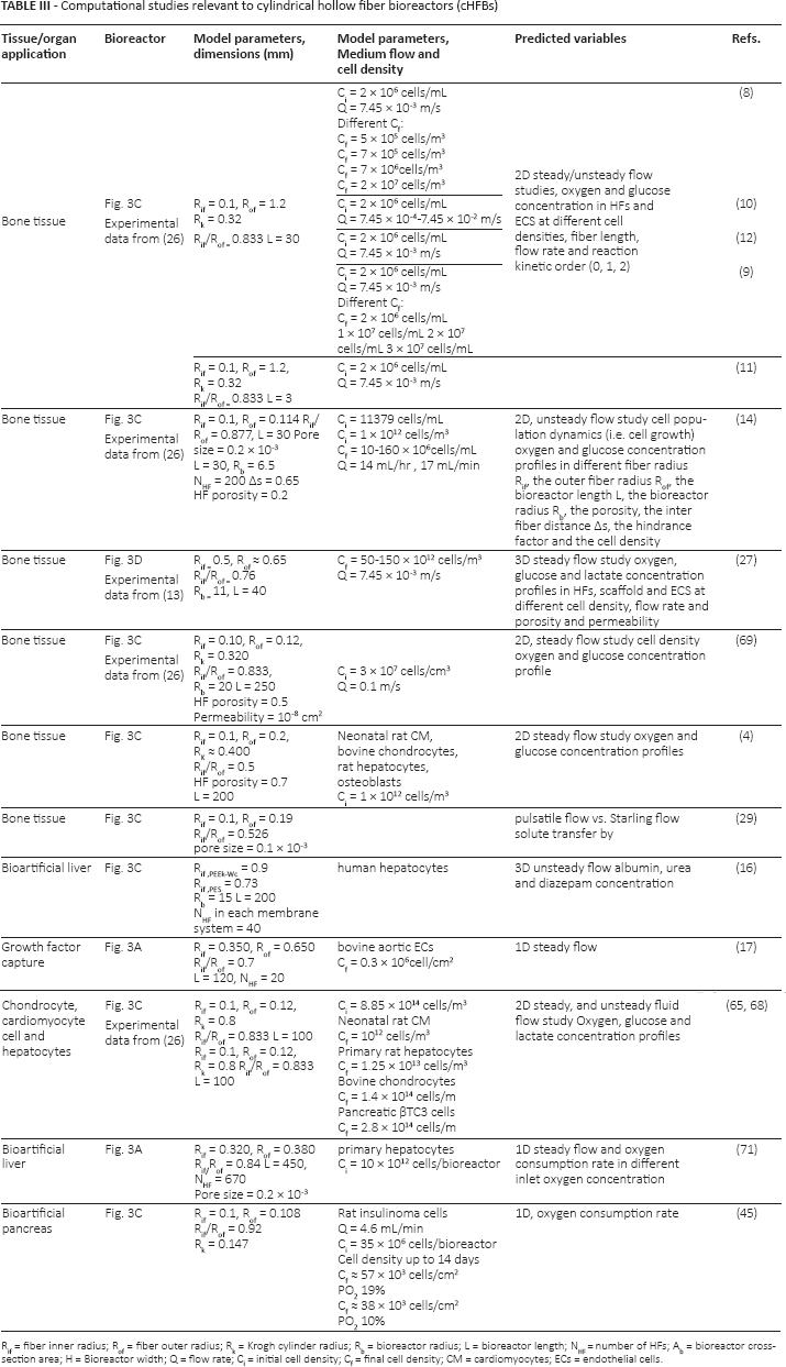
Rif = fiber inner radius; Rof = fiber outer radius; Rk = Krogh cylinder radius; Rb = bioreactor radius; L = bioreactor length; N = number of HFs; Ab = bioreactor cross-section area; H = Bioreactor width; Q = flow rate; Ci = initial cell density; Cf = final cell density; CM = cardiomyocytes; ECs = endothelial cells.
Some attempts accounting for cell growth were reported in the literature in order to improve the predictive ability of numerical modeling in HFBs. For example, a 2D computational model based on a so-called dynamic, double-porous media model (PMM) for cHFB having a configuration shown in Figure 3C was developed. The convective transport was studied under unsteady conditions. This model included both the cell growth equation and the oxygen and glucose uptake rates. The contributions of several bioreactor designs and culture parameters, including the bioreactor geometrical parameters (e.g., the inner fiber radius Rif, the outer fiber radius Rof, the bioreactor length L, the bioreactor radius Rb, the porosity, the inter fiber distance As, the hindrance factor and the cell density) (Fig. 2) to the performance of the bioreactor were simulated. The model was validated using previously published experimental results (26). The simulations demonstrated that the process and design parameters of the HFB significantly affected nutrient transport and thus cell behavior over a long-term culture period (14) (Tab. I). A further work compared the suitability of 3 bioreactor configurations: a cHFB, a suspended tube and confined perfusion bioreactors. The results have shown that the cHFB was able to maintain a higher nutrient concentration at high cell densities when compared to the other 2 bioreactor configurations. This work also emphasized previous claims suggesting that the HFB may be a suitable configuration to engineer bone tissues at high cell density (12) (Tab. I).
Concerning cHFBs as bioartificial liver devices, Hay et al developed a 1- dimensional (1D) steady state model to predict the oxygen consumption rate of hepatocytes in HFs (71). Within this field, a 3D numerical model based on the crossed HFB shown in Figure 5 was also developed. Results arising from this numerical model were in good agreement with experimentally measured data (e.g., concentration profiles of albumin, urea and diazepam). Moreover, their results have shown that the HFB configuration could significantly decrease limitations in mass transfer occurring within tissue-engineered liver constructs (16).
Conclusions and Perspectives
The experimental and computational studies described in this review demonstrate a potential use of cHFBs in the production of 3D large tissues. These studies used mostly cHFBs in the configuration shown in Figure 3C. In addition, novel cHFBs in the form of the integrated scaffold with HFs, as shown in Figure 3D, achieved promising results. The computational models simulating fluid dynamics and mass transport in the cHFBs mostly considered a 2D, simplified geometry under a steady state regime without accounting for cell behavior (e.g., growth, migration, apoptosis and ECM production). These models employe various numerical techniques to study the oxygen distribution in HFBs. The parameters adopted are mostly averaged values and do not consider the geometric heterogeneity due to nonuniform cell growth. Some of the computational models account for the 3D geometry and unsteady flow. Few of them consider cell dynamics. In most of the numerical models, there is a lack of experimental data to validate the computational predictions.
In the realm of BAOs, experimental research demonstrates that the use of cHFBs is effective in terms of cell functionality, mass transfer and safety. Indeed, BAOs have already been used as external organs on patients for short periods (Fig. 3A, B or D). The configuration shown in Figure 3D has shown the most promising results in terms of cell proliferation, cell distribution and replacement of organ functions. The computational models in this field involve few parameters and have a limited predictive capability.
Cylindrical HFBs were used for DIV-BBB models (Fig. 3E). These bioreactors were designed to investigate the microvasculature system of the brain. It was stated that such devices can be successfully be used for translational and pharmaceutical research instead of using laboratory animals (60, 61). Indeed, cHFBs represent a beneficial alternative tool for in vitro BBB modeling. In addition, researchers have experimentally tried to obtain optimal operating parameters for culture cells in a bioreactor. In vitro models based on cHFBs have shown potential applicability in therapeutic fields such as cancer research, drug testing and pharmaceutics. Although an improvement in cell viability and number by means of cHFBs has been reported in the literature, such grafts cannot be applied in vivo. Indeed, the distribution of cells in large 3D tissues obtained by HFBs does not have sufficient homogeneity or uniform cell density when compared to native tissues. Therefore, such engineered constructs are not yet functional for therapeutic purposes.
So far, the potential to translate engineered tissues arising from HFBs into clinical applications does not exist yet. Currently, the highest potential of rHFBs is in the generation of 3D models of tissue for biological research and drug delivery and testing.
In conclusion, there is a need for a more systematic knowledge of the effect of HFB geometry on parameters related to cell viability and functionality, independent of the specific tissue being regenerated. It is likely that computational models integrated with experiments will efficiently help in optimizing bioreactor design in terms of cell functionality, geometry and fluid dynamics.
Footnotes
Conflict of interest: None of the authors has any financial interest related to this study to disclose.