
Abstract
Historically, wire markers were attached to cemented all-plastic acetabular cups to demarcate the periphery and to measure socket wear. The wire shape was either a semi-circle passing over the pole of the cup, or a circle around the cup equator. More recently, “double-D” shaped markers were introduced with a part-circular aspect passing over the pole and a semi-circular aspect parallel to the equatorial plane. This configuration enabled cup retroversion to be distinguished from anteversion. In this study, the accuracy of radiographic measurement of cup orientation and wear was assessed for cups with “double-D” and circular markers.
Each cup was attached to a measurement jig which could vary the anteversion/retroversion and internal/ external rotation of the cup. A metal femoral head was fixed within the socket and radiographic images were created for all combinations of cup orientation settings. The images were measured using software with automatic edge detection, and cup orientation and zero-wear accuracies were determined for each setting.
The median error for cup version measurements was similar for both types of wire marker (0.2° double-D marker, −0.24° circular marker), but measurements of the circular marker were more repeatable. The median inclination errors were 2.05° (double-D marker) and 0.23° (circular marker). The median overall “zero wear” errors were 0.19 mm (double-D marker) and 0.03 mm (circular marker). Measurements of the circular wire marker were much more repeatable.
Introduction
A semicircular wire marker was first introduced into cemented, all-plastic acetabular cup design by Charnley in 1963 (1). The wire marker spanned a full semicircle and was located in a groove on the outer surface of the cup passing through the pole. During surgery, the plane of the semicircle was set approximately in the coronal plane. Cup wear was determined by measuring the narrowest and the widest radial distances between the femoral head surface and the wire marker on the radiographic film, and then halving the difference. This “uni-radiographic” measurement technique was superseded by the duo-radiographic technique in which wear was determined from the difference between the narrowest radial distance measurements in the current (follow-up) and postoperative radiographs (2, 3).
Later cup designs incorporated a full-circular wire marker around the equator of the cup. These designs enabled wear to be measured using a variation of the duo-radiographic technique. The change in distance between the centre of the equatorial marker (centre of its elliptical projection) and the centre of the femoral head was determined from the current and postoperative radiographs (4-6). The circular wire also enabled cup inclination to be determined from the inclination of the elliptical projection and radiographic version (7) to be calculated from the ratio of the major and minor axes of the elliptical projection (8, 9).
The manufacturers of the Charnley-type cup (DePuy) later changed the wire marker to a “double-D” configuration. This consists of a single wire which forms a semi-circle in a plane parallel to the cup equator together with a part-circle passing over the pole of the cup. One end of the polar aspect of the wire is straight and extends below the “equatorial” aspect. The purpose of this wire configuration was to enable cup retroversion to be easily distinguishable from anteversion on a radiograph. However, the projected images of both aspects of the wire are part-elliptical (10) and, because of this, the size and shape of each ellipse is difficult to determine. Consequently, measurements of cup version, inclination and wear may not be accurate.
This study tested the null-hypothesis that the radiographic measurement accuracy and precision of cup orientation and wear was not significantly different for cups with a “double-D” type wire marker configuration (DDM) compared to those with a circular marker (CM).
Materials and Methods
The measurement jig (Fig. 1a) was used to set the cup at different orientations before x-rays were taken. It was constructed entirely from Perspex and nylon in such a way that its radio-opacity simulated that of the pelvis. The outer cylinder of the jig could be tilted to set the cup at ± 20° version (anteversion positive) in 10° increments, and it could be completely rotated about a pivot in the base plate to set the cup inclination at a desired angle to the edge of the base plate. For this study we used an inclination of 35°. Two holes were drilled in diametrically opposite sides of the cup face and these accepted aluminium alloy pins which located the cup at a set angle (about the polar axis) on the face of the inner cylinder of the jig (Fig. 1b). This enabled the cup to be set at internal/external rotations in 10° increments. A tantalum marker bead was fixed in the base plate to indicate the focus point of the central x-ray beam. Its location simulated the relative position of the pubic symphysis from the hip centre.
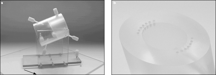
a) Measurement jig. The outer cylinder can be tilted to put the cup in ante/retroversion. The arrow shows the marker bead which was the target for the central x-ray beam. b) Inner cylinder face showing pin holes for attaching the cup at different rotational positions.
A CM cup and a DDM cup were tested (both of size 22.2 mm ID, 44 mm OD). A metal femoral head was held in place within the socket by means of a nylon screw attached to the measurement jig.
Using a Siemens Axiom Luminos dRF digital x-ray machine with a film-to-focus distance of 1150 mm, the central x-ray beam was focused on the tantalum marker and a series of x-rays were taken of the jig set at different combinations of cup orientations. These combinations comprised versions of −20° (retroversion) to +20° (anteversion) in 10° increments (0° was omitted due to the narrowness of the elliptical image), together with rotations about the polar axis of −20° (external rotation) to +20° (internal rotation) in 10° increments. For the cup with the full-circular wire marker, the cup was not rotated about the polar axis (because the image would have remained the same). Twenty images of DDM cup and four images of the CM cup were created.
The radiographic images of each cup were measured with in-house software which used edge detection to fit ellipses to the images of the wire marker and femoral head. From the size, shape and position of these ellipses, the orientation of the cup (version and inclination) and the co-ordinates of the head and cup centres were determined. Algorithms in the software corrected the measured cup version and inclination for the rotation artefact caused by the offset of the central x-ray beam from the centre of the cup (11). Using the measurement of the femoral head image, each image was calibrated to the known size of the femoral head, which had been accurately measured using Vernier callipers.
Since the purpose of this study was to determine the effect of the wire marker shape on cup wear and orientation measurements, the 2-D co-ordinates of the femoral head centre were fixed at chosen, constant values (approximating the measured centre of the femoral head) in order to eliminate very slight variations in them due to measurement error. For each measurement, a displacement vector was determined from the distance between this chosen point and the measured centre of the cup marker ellipse. Measurement error was therefore entirely due the variations in the measured position of the wire marker ellipse centre. At each orientation setting, the cup orientation and the displacement vector was determined four times. The duo-radiographic technique – variations of which are used by most wear measurement software packages (12) – determines the wear measurement from the difference between the current (follow-up) displacement vector and the reference (postoperative) displacement vector. From the four measured displacement vectors, six “wear” vectors (i.e. vector resultants of two displacement vectors) were determined from the six combinations (1-2, 1-3, 1-4, 2-3, 2-4, 3-4). Since the co-ordinates of the femoral head centre were fixed, these represented six “zero wear” measurements. The size of each “wear” vector was therefore equivalent to the “wear” measurement error.
StatsDirect software (http://www.statsdirect.com) was used for statistical calculations. Normality of the data was assessed using the Shapiro-Wilk test. For each orientation setting, the mean errors of the DDM and CM cups were compared using unpaired Student's t-tests and Mann Whitney U-tests. If a two-sided F-test was significant (unequal variances), an approximate t value was used. A p value of less than 0.05 was considered to be significant. Since, for the CM cup, rotation about the polar axis caused no change in the shape of the projected ellipse, the CM cup data at the different version settings were compared with all the data (at different rotations about the polar axis) at the respective versions of the DDM cup.
Results
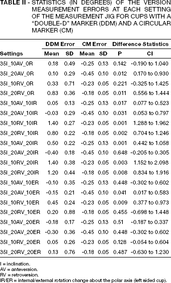
The mean “zero wear” error at each orientation setting was significantly greater for the DDM cup than for the CM cup (Tab. I). The median of the overall “zero wear” error was 0.19 mm (range 0.01 mm to 0.84 mm) for the DDM cup, and 0.03 mm (range 0.01 mm to 0.11 mm) for CM cup.
STATISTICS (IN MM) OF THE “ZERO WEAR” MEASUREMENTS AT EACH SETTING OF THE MEASUREMENT JIG FOR CUPS WITH A “DOUBLE-D” MARKER (DDM) AND A CIRCULAR MARKER (CM)
= inclination.
= anteversion.
= retroversion.
= internal/external rotation change about the polar axis (left sided cup).
For the DDM cup, most of the version measurement errors were significantly greater than those of the CM cup (Tab. II). The median of the overall version errors was 0.2° (range −0.9° to 1.9°), and that for the CM cup was −0.24° (range −0.45° to 0.18°). Version error was greatest when the cup was retroverted and internally rotated.
STATISTICS (IN DEGREES) OF THE VERSION MEASUREMENT ERRORS AT EACH SETTING OF THE MEASUREMENT JIG FOR CUPS WITH A “DOUBLE-D” MARKER (DDM) AND A CIRCULAR MARKER (CM)
I = inclination.
AV = anteversion.
RV = retroversion.
IR/ER = internal/external rotation change about the polar axis (left sided cup).
The difference between the mean inclination errors of both cups was highly significant (Tab. III) The overall median inclination errors of the DDM and CM cups were 2.05° (range 1.1° to 3.0°) and 0.23° (range 0.2° to 0.3°), respectively.
STATISTICS (IN DEGREES) OF THE INCLINATION MEASUREMENT ERRORS AT EACH SETTING OF THE MEASUREMENT JIG FOR CUPS WITH A “DOUBLE-D” MARKER (DDM) AND A CIRCULAR MARKER (CM)
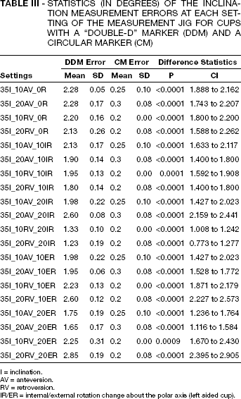
I = inclination.
AV = anteversion.
RV = retroversion.
IR/ER = internal/external rotation change about the polar axis (left sided cup).
Discussion
Since the purpose of the study was to compare the accuracy and precision of cup orientation and wear measurements for two different wire marker configurations, we were solely interested in the effects of the wire markers. Because of this, we attempted to minimise errors from other sources. Highly accurate measurement software was used (details of a validation study of this software will be published elsewhere). A single observer (the software developer, with experience of hundreds of validation measurements) took all of the measurements. In addition, errors involved in the determination of the centre of the femoral head image were obviated by choosing a common X-Y co-ordinate for all of the “zero wear” measurements of each cup. The accuracy and precision of the software is evident from the “zero-wear” measurements of the CM cup in Table I. We are confident that most of the measurement error of the DDM cup was due to difficulties in determining the accurate shape and position of the semicircular wire marker. The results presented here, therefore, probably represent the highest achievable accuracy and precision for the DDM cup, and we believe that other measurement techniques (e.g. manual) could introduce even more errors.
There was no particular reason why we chose a cup inclination of 35° for all of the measurements. It was one of three possible settings on the measurement jig. It has been shown that variations in cup inclination have no effect on cup orientation measurements as long as the measurements are corrected for x-ray beam offset (11). The cup orientation measurements were automatically corrected by the measurement software. Wear measurements would not have been affected by a different cup inclination.
The DDM aspect parallel to the cup equator was the most amenable to measurement. An ellipse could easily be fitted to its image when it comprised a half ellipse (i.e. there was no internal or external rotation) and if the version was 10° or more. However, as the rotation about the polar axis was increased, the end of the elliptical image became more open, and automatic, edge-detected ellipse fitting became less repeatable. In order to provide initial, “seed” parameters for the edge-detected ellipse, a manual ellipse first needed to be drawn (computer generated) and adjusted in shape “by eye” to correspond approximately to the shape and position of the underlying marker image. With the DDM cup, it was difficult to guess the length of the major axis of this manual ellipse to a high degree of accuracy. In addition, subsequent automatic ellipse fitting was impaired by the reduced length of the elliptical image at some of the settings. However, this technique was probably the only way of determining the parameters of the underlying elliptical image with at least some degree of accuracy.
Measurements of the polar aspect of the DDM were attempted but, even with our sophisticated software, it was very difficult to fit an accurate and reproducible ellipse to that portion of the wire image. The reason for this is that the polar aspect of the wire marker is only a partial ellipse: it is open ended, and its “height” along the polar axis is appreciably shorter than its major axis – especially at high version angles. Because of this, for a given measurement error band (Fig. 2), a large number of ellipses of different sizes and positions can be fitted to the partial elliptical image.
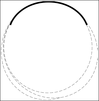
The thick line represents the shape of the polar aspect of the DDM wire marker image. Its thickness represents the error band (scatter) for edge detected points on the image of this wire. The dashed lines represent just some of the possible ellipses that could be fitted within this error band.
A reasonably good accuracy of the DDM cup orientation was achieved with our software, but this could not have been achieved with manual measurement techniques (ruler and pencil) because of the open ended extremity problem mentioned above (Fig. 3). A systematic error of 1°– 2° in the inclination measurements of the DDM was due to the inclination of the “equatorial” wire within the relatively wide recess in which it was located. The wire was high near the “wrap around” – where it started to bend toward the polar aspect – and low at the opposite end. This effect was not just a feature of our test cup: it is common to all cups of this type. If the inclination values of the DDM cup were corrected for this anomaly, the inclination errors would be only a fraction of a degree – as with the version errors.
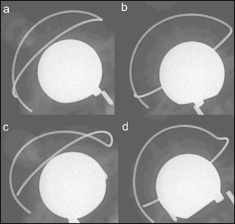
Radiographic images of the DDM cup set at different orientations: a) 20° anteversion, 20° internal rotation; b) 10° retroversion, 20° internal rotation; c) 20° anteversion, 20° external rotation; d) 10° retroversion, 20° external rotation.
The accuracy and repeatability of the “zero wear” measurements of the DDM was relatively poor (Tab. I). It was worst when the cup was externally rotated (left side) and, again, this was probably due to the missing extremity of the elliptical image in this orientation.
Accuracy and precision were best for the CM cup (Tabs. I-III). In our opinion, this accuracy and precision outweigh the single advantage of the DDM cup (distinguishing retroversion). Researchers and clinicians who plan to measure cemented cup orientation or wear accurately should choose cups with circular, equatorial wire markers.
Footnotes
Acknowledgements
We thank Elaine Broxholme, Lyndsay Cunningham and Janet Ellison for assisting with the radiography.