
Abstract
BACKGROUND:
In recent years, exoskeleton robot technology has developed rapidly. Exoskeleton robots that can be worn on a human body and provide additional strength, speed or other abilities. Exoskeleton robots have a wide range of applications, such as medical rehabilitation, logistics and disaster relief and other fields.
OBJECTIVE:
The study goal is to propose a lower limb assistive exoskeleton robot to provide extra power for wearers.
METHODS:
The mechanical structure of the exoskeleton robot was designed by using bionics principle to imitate human body shape, so as to satisfy the coordination of man-machine movement and the comfort of wearing. Then a gait prediction method based on neural network was designed. In addition, a control strategy according to iterative learning control was designed.
RESULTS:
The experiment results showed that the proposed exoskeleton robot can produce effective assistance and reduce the wearer’s muscle force output.
CONCLUSION:
A lower limb assistive exoskeleton robot was introduced in this paper. The kinematics model and dynamic model of the exoskeleton robot were established. Tracking effects of joint angle displacement and velocity were analyzed to verify feasibility of the control strategy. The learning error of joint angle can be improved with increase of the number of iterations. The error of trajectory tracking is acceptable.
Keywords
Introduction
Assistive exoskeleton robot is a kind of robot possessing the function of supplementing or completely replacing human limbs [1]. Assistive exoskeleton robot combines human intelligence and robot strength and is controlled by the wearer [2, 3]. As for special staffs who need bearing heavy load and continuous hours of work, assistive exoskeleton system can control each driving joint to make wearers bear greater load with little or no loss of physical strength and longer work time. For the disabled or the elderly with limited mobility, assistive exoskeleton robot can provide effort for the wearer to help them complete corresponding movements, which plays a certain auxiliary role in rehabilitation treatment [4, 5, 6].
As a human body auxiliary system, assistive exoskeleton robots are widely used in military, industry, aviation, medical treatment and so on [7]. Exoskeleton robots have been developed by a number of researchers for various applications [8, 9, 10, 11]. In terms of military, the “BLEEX” assistive exoskeleton robot was designed by University of California, Berkeley [12, 13, 14, 15, 16, 17]. The exoskeleton robot adopted bionics design and the design would directly transfer the weight of load to the ground through the main body of the exoskeleton without passing through the wearer’s body. Between 2005 and 2008, Berkeley Bionics and Human Engineering Laboratory developed three exoskeletons: the Human Universal Load Carrier (HULC), the Exo-Hiker and the Exo-Climber [18]. HULC could be applied to military personnel involved in long-duration missions. The EXO-Hiker adopts pneumatic spring to drive the hip joint, which is suitable for load walking with long distance and time. Exo-climber introduces a hydraulic cylinder as a hip joint drive mode, which is suitable for up and down hills and stairs with loads for a long distance and time. In terms of industry, the Power-Loader designed and produced by Ishida et al. uses the direct force feedback control system to carry out intention identification and motion prediction to achieve human-machine cooperative control, which can realize the functions of assistance and load bearing, and can be applied to the logistics, disaster relief and handling industry [19]. Then, the DSME, a lower limb exoskeleton designed by Korea’s Chu et al., uses hydraulic cylinder to drive hip and knee joints. The exoskeleton can deliver a load of 66 pounds and run continuously for 3 hours, which is widely used in logistics industry [20]. In terms of aviation, Kwa et al. developed and designed the X1 exoskeleton, which can help the wearer maintain muscle strength in the space environment to provide assistance for astronauts, and also apply to rehabilitation field [21, 22]. The exoskeleton weighed about 26 kg has four active joints and six passive joints driven by motor. In terms of medical treatment, between 1999 and 2005, The University of Tsukuba in Japan designed 5 HAL exoskeleton robots [23, 24, 25]. Among them, HAL-5 uses electromyographic signal as a control signal for the robot, which not only has assist effect, but also can be used as a medical instrument in the field of rehabilitation [26, 27].
In order to satisfy wearable coordination and comfort of daily assistance, this paper studies the human-machine fusion characteristics of a lower limb assistive exoskeleton robot. In this paper, the mechanical structure of exoskeleton was designed based on bionics principle. The driving module and passive energy storage components are designed in the form of active and passive, and elastic components are used in the passive joints to protect the lower limbs and reduce energy consumption. A gait prediction method based on Kalman filtering was designed. Iterative learning control strategy was used to realize trajectory tracking. Finally, assistive experiment results indicate that the exoskeleton robot possesses assistance function and control strategy is effective.
Mechanical strucrure
Mechanical structure of the assistive exoskeleton robot.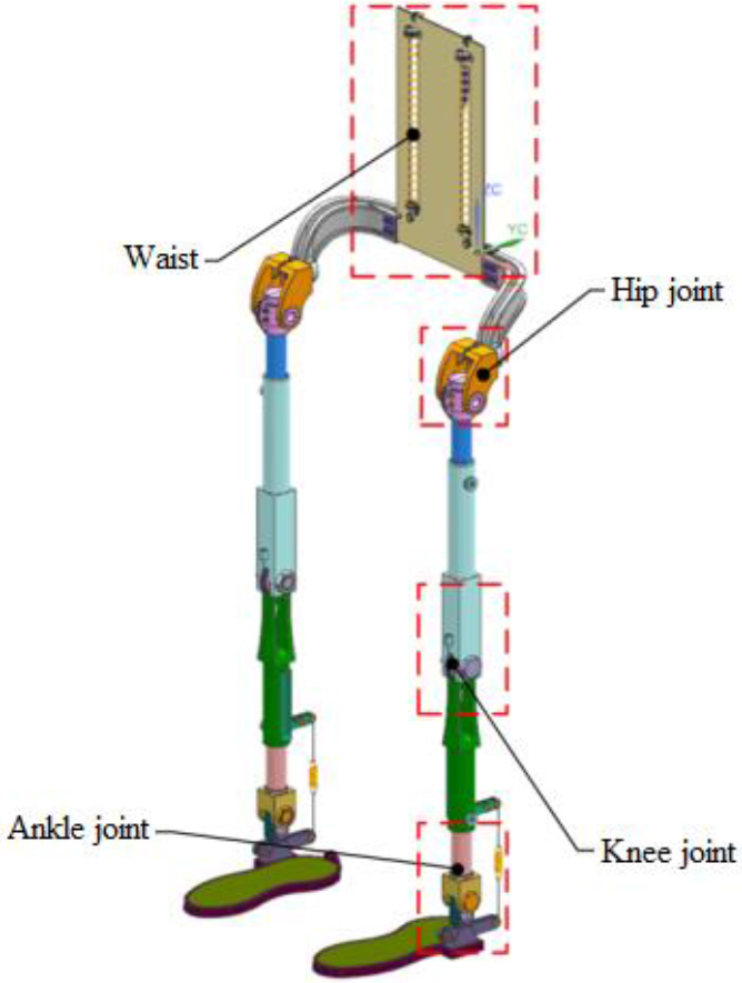
Mechanical structure of the assistive exoskeleton is shown in Fig. 1. The exoskeleton has 7 active degree of freedoms (DOFs) for each leg: 3 active DOFs for the hip joint and ankle joint, respectively, and 1 active DOF for the knee joint. The flexion DOF of knee joint is set to drive. Elastic energy storage elements are set for flexion and extension DOFs of other joints to store and transform the work done by body gravity during walking to achieve the effect of assistance. The waist and leg length are designed for compatibility to suit different wearers.
Structural design for transferring load force: (a) schematic diagram (b) three dimensional diagram.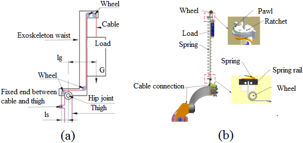
In the sagittal plane of human body, the structure in Fig. 2 is adopted to transfer the load force. The load connected to spring is transferred to exoskeleton thigh through wheel transmission and fixed up. If keeping stationary state under load, the torque
Where
However, when the load is transferred to exoskeleton thigh, the torque
Where
If the length of
Spring as energy storage element is in series with cable. One end of cable is fixed to the backside, and the other end is fixed to hip joint and thigh. When thigh is raised, stretched spring will provide pull to raise thigh forward through cable connection. When thigh is recovered, the work done by gravity of lower limb will be converted to elastic potential energy of spring. Therefore, the structure not only balance the hip joint torque so that load gravity is transferred to the thigh, but also can be as passive storage element to reduce the loss of muscle energy.
Knee joint design can be realized based on four-bar linkage structure. But this method makes mechanical structures more complex and dynamics models difficult to solve. Therefore, knee joint design of the exoskeleton in this paper adopts revolute pair of one DOF.
Structure diagram of knee joint drive.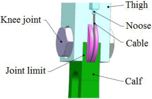
Structure diagram of knee joint drive is shown in Fig. 3, the cable is connected via a wheel. One end is connected to the motor rotor and the other end is connected to the lower leg of the exoskeleton robot below the knee joint. The motor achieves spatial force transfer through the combination of Bowden cable and overwheel.
Spring passive storage element is adopted to design ankle joint, which can convert negative work done by gravity during walking to elastic potential energy and store it. Then elastic potential energy is released when the lower leg exerts force. The output force of soleus and total energy consumption are compared and analyzed with or without energy storage components through OpenSim’s energy metabolism module. The results indicate that the output force of soleus and total energy consumption are in most cases lower with the energy storage device than without the energy storage device. The angular momentum output of the ankle using the elastic energy storage device is also less than that of the ankle without the energy storage device. According to the above analysis, it can be seen that the exoskeleton with energy storage element designed in the ankle joint can reduce the energy consumption of the wearer and thus achieve the effect of energy saving during the force generation process of the lower leg support, namely the support stage.
Structural design of ankle joint.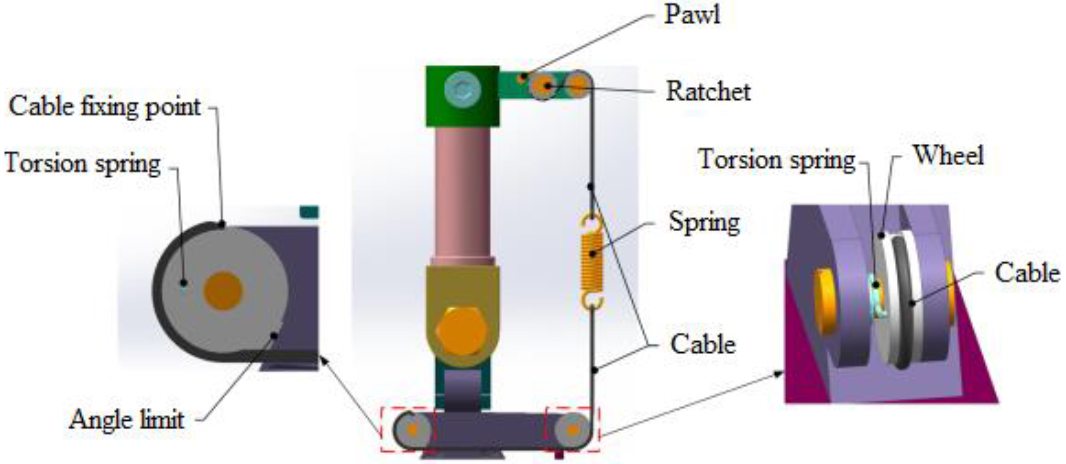
Structural design of ankle joint is shown in Fig. 4. The relationship between distance during two hanging points of spring and the rotation angle of ankle joint is analyzed. In one gait cycle, the distance between hanging points of spring changes 19.5791 mm when the rotation angle of ankle joint is from
Where
The torsion spring is set to give the cable a pre-tightening force during swing phase, so that the cable always keeps straightening state. The spring starts to stretch and store energy in swing phase. The stiffness of the spring should be set in accordance with Hooke’s law. Thereinto, when the shape variable of spring is 11.5574 mm, the output force of spring is about 123.5 N.
Kinematic model of the lower limb exoskeleton.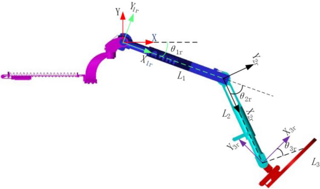
Kinematics model
Kinematic model of the lower limb exoskeleton is established according to Denavit-Hartenberg (D-H) method, as shown in Fig. 5.
Firstly, positions of lower limb relative to torso can be determine through coordinate transformation; then, positions of human body relative to the world coordinate system are measured through coordinate transformation once again; finally, positions of each lower limb part relative to the world coordinate system can be caculated.
Positions of lower limb joints in world coordinate system can be calculated by following formulas
The connecting rod parameters of exoskeleton presented are shown in Table 1.
Connecting rod parameters of exoskeleton
Dynamics is the study of the relationship between motion and force on a body. Lagrange equation is used for dynamics model and analysis in this paper. Lagrange function can be expressed as
Where
Then, the dynamics equation of system is
Where
The Lagrange equation is written in matrix form as follows
Where
1. Dynamics model of swing phase
The lower limb exoskeleton is generally simplified as a two-rod model with hip joint end fixation when it is in the swinging phase. Assume that the hip joint is fixed, its rotation center is the origin, and the coordinate system is established as shown in Fig. 6a.
(a) Swing phase model (b) Support phase model.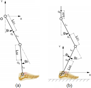
The total kinetic energy and total potential energy of the system are expressed as follows
According to Eqs (10) and Eq. (11),
Therefore inertia matrix
2. Dynamics model of support phase
When the lower limb exoskeleton is in the support phase, it can be simplified as a three-rob model with shoe end fixation as shown in Fig. 6b. The total kinetic energy and total potential energy of the system are expressed as follows
The dynamics equations of system can be expressed as
The dynamics model of support phase can be expressed as
Where
Structure neural network.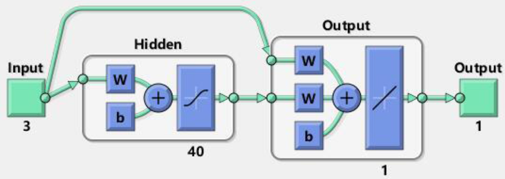
Prediction results of neural network.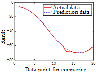
A gait prediction based on neural network is designed. The number of hidden neural network layers is 40, and the neural network structure is shown in Fig. 7. The collected data are the joint angle data of one walking cycle and the position of the corresponding gait cycle of one leg. The input data are hip angle and ankle angle of the right leg and plantar pressure of the right foot, and the output data are knee angle of the right leg. After learning the data, the prediction results are shown in Fig. 8.
Iterative learning control (ILC) has better tracking effect in handling repetitive control tasks. ILC does not depend on the exact mathematical model of system, but follows the timeline and iteration axis which are independent at operational process. Therefore, ILC is appropriate for lower limb exoskeleton system with imprecise mathematical model and repetitive tasks. Closed-loop iterative learning control strategy is designed, as shown in Fig. 9.
Closed-loop iterative learning control strategy block diagram.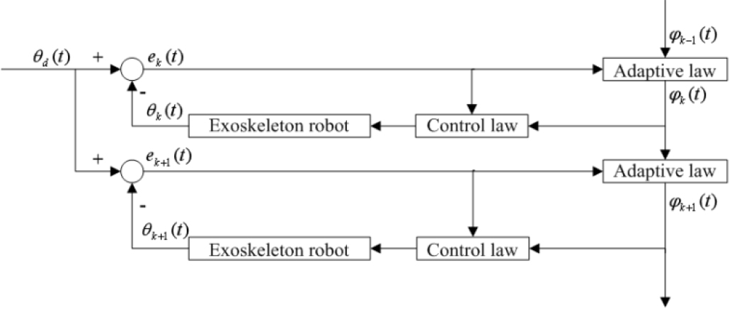
According to the established dynamics model, the swing phase control law and adaptive law can be respectively designed as
Where
The support phase control law and adaptive law can be respectively designed as
The schematic of control strategy for swing phase and support phase is shown in Fig. 10.
Schematic of the control strategy for (a) swing phase and (b) support phase.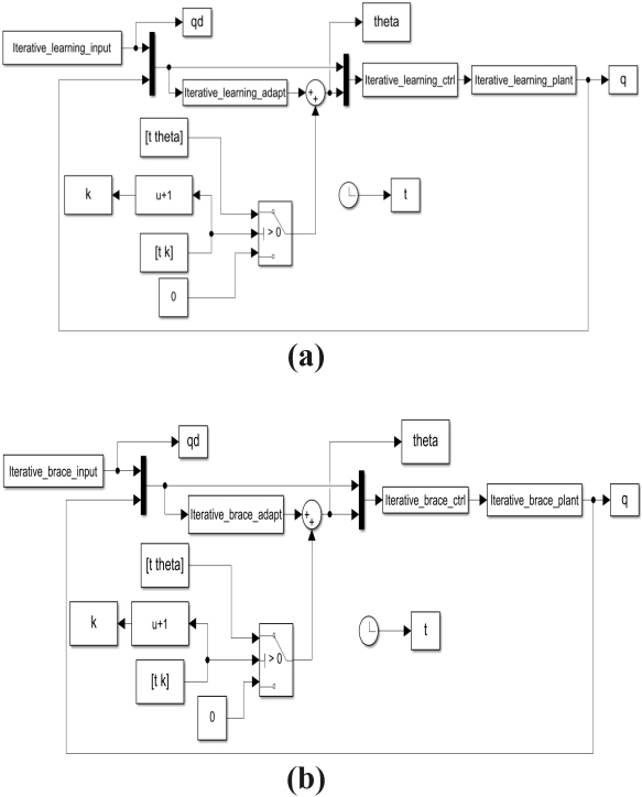
(a) Maximum position tracking error of the swing phase (b) Maximum position tracking error of the support phase.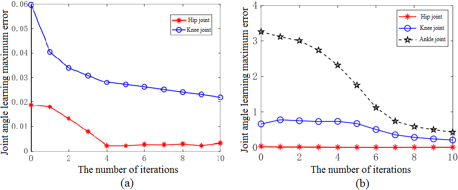
By inputting the target joint angle data and combining with the established dynamic model of the swing phase and support phase, the iterative learning control was carried out. Error analysis results of swing phase and support phase are shown as Fig. 11. It can be seen that the learning error of joint angle decreases gradually with the increase of the number of iterations. And the errors of hip and knee joint are very small in both the support phase and the swing phase. However, because of the small number of iterations, the tracking error of ankle joint in the modal simulation of the support phase is relatively large.
Experimental platform
Experiment platform of exoskeleton prototype.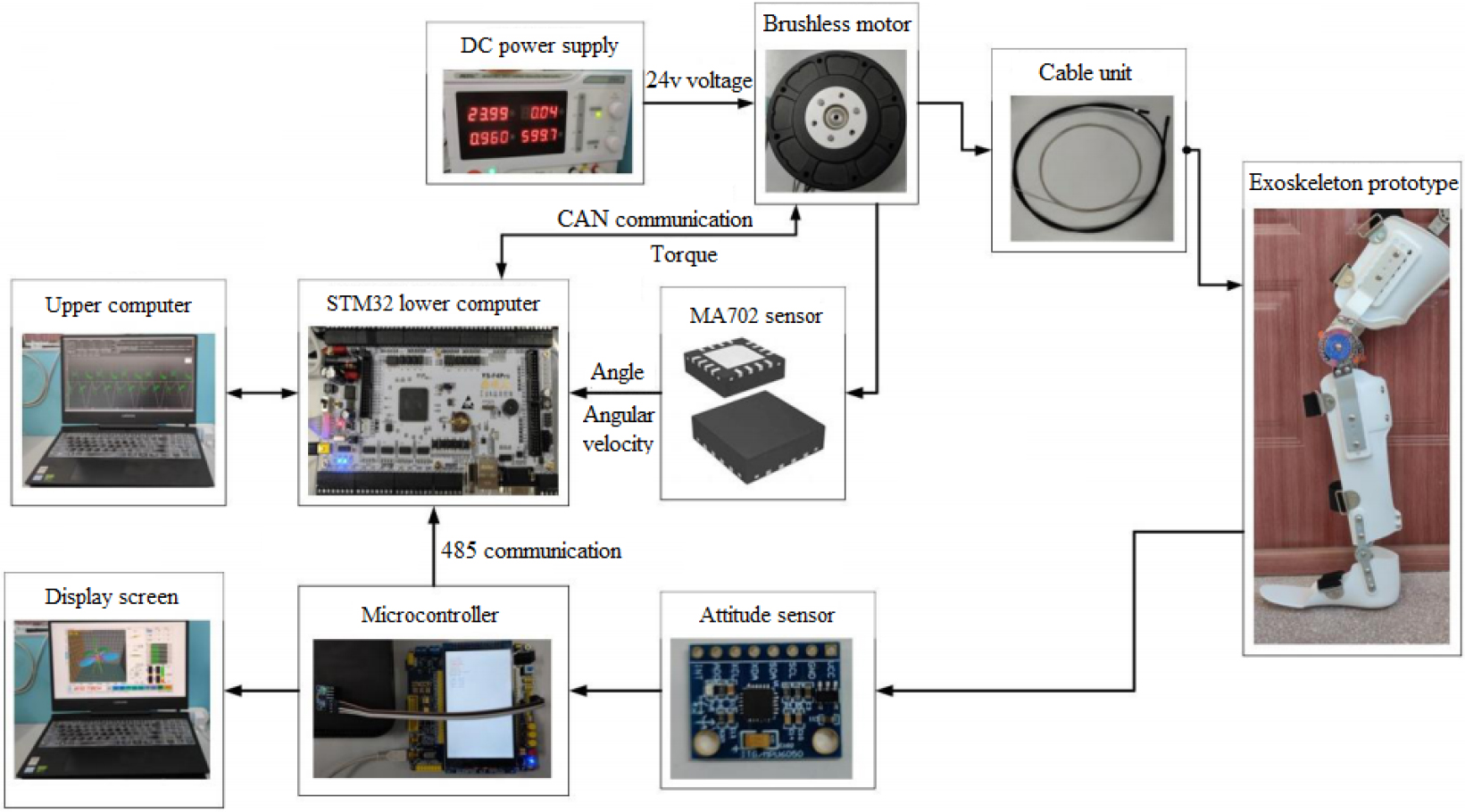
The prototype experiment was carried out to verify theoretical feasibility. The experiment platform is shown as Fig. 12. The exoskeleton robot system consists of upper computer, lower computer, and exoskeleton prototype. The communication between the upper computer and the lower computer is completed by ST-link. STM32 is used to control brushless motor and receive motor output torque through Controller Area Network (CAN) communication. In addition, STM32 is also used to receive the angle and angular velocity feedbacked by MA702 encoder. The angular displacement and angular velocity of exoskeleton prototype are collected by the microcontroller through the MPU6050 gyroscope, and the data are send to lower computer by the microcontroller through 485 communication.
Assistive experiment is conducted when exoskeleton prototype works during one gait cycle. To track the target curve, the torque output by the motor increases significantly compared with the no-load state. According to the motor output torque curve shown in Fig. 13, when the load increases, in order to track the given position, the motor will output more torque to drive the lower limbs of the exoskeleton robot to reach the given position, so the motor output torque increases. The effective output power of the drive module is equal to the output power when it is assisted minus the output power when it is unloaded. By comparing the output torque of the no-load motor, the motor outputs a lot of effective output power. It can be seen that the motor can drive the exoskeleton robot to achieve the power effect.
The motor output torque curve under no-load and load.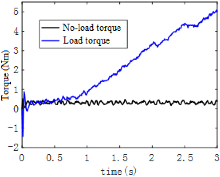
Results of assistive experiment.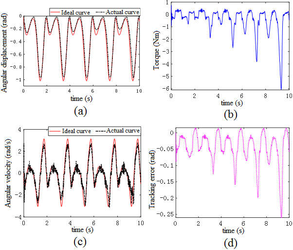
The experimental results are presented in Fig. 14. As shown in Fig. 14, the state in first two seconds is the no-load phase of motor, and the load is gradually increased from 2 to 10 second. Figure 14a and c indicate that the exoskeleton prototype can well track the target curve of given joint angular displacement and angular velocity. We can see from Fig. 14b, the increase of load causes the increase of motor output torque compared with the no-load phase. Angular displacement tracking error is shown in Fig. 14d. With the increase of load, the error of displacement tracking becomes larger in a short time. Generally speaking, the error meets the requirement of assistance. In exoskeleton prototype, the output torque of the motor is the same as the no-load torque when the cable is under pressure, whether it is loaded or not, because only tension is effective in cable transmission. When the cable is pulled, it drives the lower leg to rotate. As the load gradually increases, the output torque of the motor increases. Therefore, by obtaining the effective output torque of the motor, the motor can drive the exoskeleton prototype to achieve the effect of assistance.
A lower limb assistive exoskeleton robot is introduced in this paper to meet needs of wearer for assistance. The mechanical structure of exoskeleton robot is designed based on bionics. Kinematics model according to D-H method and dynamics model according to Lagrange method are established. A gait prediction based on neural network is designed, which lays the fundation for control strategy. Iterative learning control strategy is used to realize trajectory tracking. Tracking effects of joint angle displacement and velocity are analyzed. The error of trajectory tracking is acceptable. Assistive experiment is conducted to verify theoretical feasibility. Experimental results show that the exoskeleton robot possesses assistance function and control strategy is effective. A controller performance evaluation standard and safety performance evaluation index for lower limb exoskeleton robot need to be designed in further work.
Footnotes
Acknowledgments
This work was supported by the National Natural Science Foundation of China (52175006), Natural Science Foundation of Heilongjiang Province (H2023E064), 2023 Annual Research and Cultivation Project of Jilin Agricultural Science and Technology University.
Conflict of interest
None to report.