
Abstract
Actors in the Architecture, Engineering, Construction, Owner and Operation (AECOO) industry traditionally exchange building models as files. The Building Information Modelling (BIM) methodology advocates the seamless exchange of all information between related stakeholders using digital technologies. The ultimate evolution of the methodology, BIM Maturity Level 3, envisions interoperable, distributed, web-based, interdisciplinary information exchange among stakeholders across the life-cycle of buildings. The World Wide Web Consortium Linked Building Data Community Group (W3C LBD-CG) hypothesises that the Linked Data models and best practices can be leveraged to achieve this vision in modern web-based applications. In this paper, we introduce the Building Topology Ontology (BOT) as a core vocabulary to this approach. It provides a high-level description of the topology of buildings including storeys and spaces, the building elements they contain, and their web-friendly 3D models. We describe how existing applications produce and consume datasets combining BOT with other ontologies that describe product catalogues, sensor observations, or Internet of Things (IoT) devices effectively implementing BIM Maturity Level 3. We evaluate our approach by exporting and querying three real-life large building models.
Introduction
The global Architecture, Engineering, Construction, Owner and Operation (AECOO) industry contributes significantly to the economy of industrialised and emerging countries (e.g. 2.5M employees [21] and 15.9 % of the gross value added in Germany [20]). The specific characteristics of the industry make it challenging to successfully handle projects in this domain. One challenging characteristic is the fragmented structure of the industry, as it is composed of numerous small and medium-sized companies. In addition, interdisciplinary stakeholders from different trades each using own special software tools [6] need to work together and exchange information over the whole life cycle of a project [62]. Current approaches rely on the establishment of a temporary project organisation for each new project. Therefore, it is challenging to carry the gathered project information and best practices onwards to the next project as stakeholders change.

BIM levels of maturity, with the web-based BIM Level 3 on the far right (copyrighted image: [7]).
During the whole life cycle of a building, vast amounts of data are generated, exchanged and processed. The facilitation of a seamless exchange of project information over the whole life cycle of a construction facility as well as between multiple, interdisciplinary stakeholders is a fundamental necessity for the successful accomplishment of these projects. Due to the fragmented structure of the industry, this information supply chain is often reestablished from near scratch with each new project organisation, resulting in new custom data structures for every project, represented in individual ever-changing unstructured spreadsheets and documents.
Building Information Modelling (BIM) is a methodology under research since decades [18], which advocates the seamless exchange of all information between related stakeholders by the use of digital technologies. It allows addressing the above-described problems in the information exchange in AECOO projects. A growing interest can be found in the BIM method, even for existing buildings [68], and its adoption gains momentum as, similar to other industries, the AECOO industry experiences a ubiquitous introduction of Information and Communication Technologies (ICT) in the course of the digital transformation of the domain. By now, BIM as a method has established itself globally in the construction industry, making the industry shift significantly towards full digitisation. Yet, it still suffers from the diversity of (custom) data structures and use of unstructured data in documents (BIM Level 2).
This shift towards the use of BIM happens according to a number of maturity levels. Figure 1 depicts the four maturity levels that are defined by Bew and Richards [7] for the BIM methodology. These levels indicate how maturely the BIM methodology is implemented in a given company, and each level outlines the technological requirements for its successful realisation at that level. These levels serve as a guideline for the evolution steps of the adoption of BIM by industry and policy makers [7]. Maturity level 0 is the “Pre-BIM”-phase, where building information is exchanged in an uncoordinated manner based on drawings (CAD drawing and paper-based exchange). In Level 1, companies and stakeholders collaborate in a file-based manner, and focus mostly on 2D and 3D geometric modelling; whereas companies in Level 2 work with full BIM models, which are typically understood to be complex 3D models enriched with big amounts of information (material data, usage data, design constraints, etc.). Collaboration in Level 2 is mainly file-based still. When achieving the highest maturity Level 3, it is envisioned that process and information is exchanged purely on a web-scale and fully integrated over disciplines and companies. BIM Level 3 can be compared to BIM Level 2, similar to how the Web of Data can be compared the Web of Documents.
Currently, the AECOO industry is situated at Level 0, 1, or 2 of this diagram, depending on the region in the world, where (manual) file-based information exchange is still the state of the art. Exchange approaches rely on files, e.g. Industry Foundation Classes (IFC) [33], and file containers, e.g. ISO 19650-1 [34], or Common Data Environments (CDEs) for the centralised web-based storage and exchange of construction-related files (e.g. Autodesk A360,1
In essence, BIM Maturity Level 3 is, apart from high-level descriptions [8], rather undefined, and approaches for implementation are missing (see Section 2). However, it is clear that, for BIM Maturity Level 3, information is exchanged on the Web using open standards, and interoperable and decentralised model servers allow collaborative work on interoperable models and structured data. From this assumption, one may define the following general requirements for BIM Maturity Level 3:
Support of web-based information exchange [8];
Use of an information hub to allow collaborative, web-based workflows among interdisciplinary stakeholders [8];
Use of a set of interoperable, flexible, and open, standards covering different domains;
Support of distributed data integration, linking and tracking at data level.
The vision of the Linked Building Data (LBD) Community Group (CG)3
In this paper, we report on a collaborative effort led in the context of the LBD CG to develop a lightweight [16] and extensible ontology4
An ontology is a formal, explicit specification of a shared conceptualisation of a domain [26].
The rest of this article is organised as follows. In Section 2 we provide an analysis of the current state of the art in moving the AECOO industry in the direction of the Web of data. Then Section 3 details the most recent version of the BOT ontology, and the proposed conceptual alignment to the DOLCE Ultralite ontology [23], and to other related ontologies. Section 4 describes how BOT is expected to be used in combination with other ontologies. It also reports on existing applications that produce or consume BOT datasets. Section 5 provides an evaluation of the export and query of BOT datasets for three large building models.
Industry practitioners actively work towards BIM Maturity Level 3, and, as a result, different open source community-based software projects have evolved in the past years to fulfil requirements REQ1 and REQ2 (e.g. Flux.io,5
Discontinued, no longer online.
In terms of information exchanges, the standard schema for the exchange of BIM data is the Industry Foundation Classes (IFC) [33], which is a data model described in EXPRESS [31] and which has a strong focus on the representation of 3D geometry [46]. However, IFC does not fulfil requirements REQ3 and REQ4 in that it is not web-compliant, and fails at enabling the integration of building data with other types of data on the Web. Arguably, a better move to bridge this gap is to adopt the Linked Data principles [5] including the use of semantic web standards and technologies [17] such as the Resource Description Framework (RDF) [42], the Web Ontology Language (OWL) [30], and the SPARQL Protocol and RDF Query Language (SPARQL) [29]. Therefore, various works investigated how Semantic Web technologies can be used for the AECOO industry. We overview these works in the rest of this section, using as a starting point a recent survey by Pauwels et al. [49]. We hereby also briefly indicate how geospatial data standards fit obtaining BIM Level 3 using semantic web technologies.
A pioneer initiative aiming at integrating IFC and OWL was named ifcOWL and proposed in 2005 and 2009 by Beetz et al. [3,4].
The ifcOWL ontology and simplification initiatives
Heavily relying on this early work, Pauwels and Terkaj [48] implemented a direct mapping of the EXPRESS schema to OWL, and applied this transformation to the IFC EXPRESS schema to produce the ifcOWL ontology.8
A) Complex structure of ifcOWL The proposed systematic transposition results in modelling choices that are inconsistent with the best practices in the Semantic Web domain (e.g., defining a class for booleans or relations). Also, the resulting ifcOWL includes many syntactical constructs stemming from the EXPRESS source schema (e.g. ordered lists, objectified relations, objectified properties, ‘select’ classes, and ‘enumeration’ individuals). Even though this enables round-tripping between IFC documents and ifcOWL ontologies, it makes ifcOWL, like IFC itself, too complex, hard to manage, hard to understand, and also makes reasoning highly inefficient [46,63].
B) Size of ifcOWL ifcOWL contains in a single ontology all the terms of the IFC specification, including terms related to lists, datatypes, time scheduling, cost estimation, or quantitative units. This size of ifcOWL hampers its understanding and usability by developers that may need just a few concepts. In other words, the highly needed modularity and extensibility are entirely missing. For example, the latest version of ifcOWL for IFC4_ADD2 consists of 1331 classes and 1599 properties. Ongoing work aims at extending IFC towards roads [36] and bridges [69], which will ultimately make the resulting ifcOWL even bigger. However, Terkaj and Pauwels [64] have later suggested an approach to generate a modular version of ifcOWL, based on the modules that are present at the core of IFC.
Aiming to resolve the above drawbacks, a number of efforts then aimed at defining mechanisms to automatically simplify building models described with the ifcOWL ontology (which can be referred to as ifcOWL datasets). IFC Web of Data IFCWoD (IFCWoD) [43] and SimpleBIM [47] both cut away elements like geometric data and intermediate EXPRESS-derived relation instances between objects. These approaches have been proven successful, yet they are amendments to an ontology that is intrinsically insufficient because of its backlog (the IFC EXPRESS schema). Indeed, the result remains relatively close to the EXPRESS version of IFC, instead of aiming first at best practices and publishing modular ontologies that are based on known and proven ontology design patterns.
In terms of simplification for ifcOWL, BimSPARQL [70] uses another approach that leverages the application of SPARQL Inferencing Notation (SPIN) rules to provide shortcuts, thereby making it simpler to query an ifcOWL dataset. This allows for bypassing the intermediate node between a space and its contained elements, for example. The work also demonstrates rules that perform geometric operations on geometry, and in general, it showcases a promising approach for data extraction from BIM models. The size-related drawbacks of ifcOWL are, however, still persistent with this approach, and a new semantic web-born set of ontologies is needed for this industry.
Alternative approaches aimed to make building data available over the web in a more structured format, typically also deploying semantic web technologies.
Metadata in IFC files Beetz et al. [2] proposed to use existing features of the IFC model to allow for the direct incorporation of meta-data in the IFC document that give access to external RDF data. In this approach, the core of IFC, and in particular the geometry, can still be used, while also allowing to link to external RDF data. This approach addressed the extensibility issues of IFC, while avoiding to abandon the EXPRESS schema for IFC. Although the resulting IFC documents are compatible with IFC, they still centralise all the information. Therefore, BIM Level 3 requirements REQ2 and REQ4 could not be covered. At best, this presents a transitional approach towards the implementation of BIM Level 3.
Annotation of online resources with IFC concepts Gao et al. [25] defined a domain ontology of IFC, with the goal to annotate online resources with the IFC data model, and thus use IFC in combination with semantic web technologies to perform information retrieval (IFC-IR) [24,40]. They demonstrate with their approach that IFC data on the Web can efficiently be retrieved using SPARQL queries. However, this approach does not fulfil BIM Level 3 requirement REQ3, as the file-based exchange mechanism still prevails.
BIMSO/BIMDO The foundation ontology BIM Shared Ontology (BIMSO) has been defined for the AECOO industry, with the purpose of being extended with various building domain ontologies [44]. The authors claim that the ontology only contains a few classes and relationships scoped at describing a building’s elements, levels, spaces and construction phases, and relies on the full Uniformat II classification system for further organising the elements. A separate ontology, the BIM Design Ontology (BIMDO), provides the necessary object properties to describe relationships between elements, subdivision of zones and to quantify these relationships [44]. However, these ontologies have not been made publicly available, which violates the first principle of the Linked Data deployment scheme.
The W3C LBD CG
Many other ontologies have been developed for the AECOO domain, subsets of it, or related domains such as sensors and actuators, or the IoT. This consistently leads to contradictory redefinition of common terms [56] such as “building”, which, as of April 2019, is defined in 690 separate ontologies in the Linked Open Vocabulary [66].9
The W3C LBD CG was created to bring together experts in the area of BIM and Web of Data technologies. One of its goals was to identify and align existing initiatives to model building data across the life cycle of buildings. The alignment between the terms in these ontologies was studied10
Part of the data in these categories is not specific to buildings and may be described using existing standardised vocabularies, according to the best practices [9]. For example: (1) the Semantic Sensor Network Ontology (SOSA)/Semantic Sensor Network Ontology (SSN) ontology [28] can be used to describe observations and actuations of properties in buildings, (2) schema.org can be used to describe products, (3) SAREF can be used to describe IoT devices [15].
When no existing ontology could be reused, ontology proposals were made. For example, the Ontology for Property Management (OPM) [55] can be used to describe property states, thereby allowing property values to evolve over time while keeping track of their history. It extends the SEAS ontology [37,38] and the Provenance Ontology (PROV-O) [35].
Finally, it has been decided that the group was legitimate to develop a lightweight ontology providing a high-level description of the topology of buildings including storeys and spaces, the building elements they may contain, and the geometry of these spaces and elements. The rest of this article describes the result of this development, the BOT ontology, which is currently the most mature report of the W3C LBD CG [57].
The group aimed at creating a lightweight BOT ontology that would not have the same drawbacks found in IFC in terms of size and complexity. Re-use of existing ontologies was an important priority, which includes ontologies for specialised areas, as mentioned above, such as sensor data, product data, geometry, and so forth. Such detailed ontologies are not to be incorporated in BOT, yet, they are meant to be linked to whenever BOT-compliant RDF data is produced (see further on in this article). As an example, the geospatial domain is a very important reference domain for the AECOO industry. Instead of including the geospatial domain within the scope of BOT, the group aimed to limit to referential topological concepts of a building, which can then reference geospatial data that is represented using its own standards (e.g. CityGML).
The scope of BOT is to explicitly define necessary relationships between the sub-components of a building. As such, it aims to provide the means for representing interlinked information in a future (semantic) web driven AECOO industry, satisfying the recommendation of reusing terms already described in well-known vocabularies wherever possible [9].
The first version of BOT was presented in [56] and an increment in [58]. Since then, the ontology has been further extended to accommodate modelling issues raised by the community. This section first overviews the competency questions of the ontology, then provides an overview of the current version v0.3.1 of BOT, then details its main components, and finally discusses the alignments with related ontologies.
Overview of the BOT ontology competency questions
The Competency Questions (CQs) for BOT were raised by the community during the W3C LBD CG group community calls, on the public mailing list, during the Linked Data in Architecture and Construction (LDAC) workshop series, and on the project repository on GitHub.11
What are the zonal constituents of the overall building (e.g. site, building, storey, space)?
What smaller zones are contained inside the larger zone (e.g. space zone contained in the storey zone; contained in the building zone; contained in the site zone)?
What zone(s) are adjacent to or intersecting with a zone?
What are the tangible building elements that the building consists of and what are the sub elements of these building elements?
Which element(s) are contained inside the 3D-extent of a particular zone? Which elements are adjacent to the zone? Which elements are intersecting with the zone?
How to assign metadata to a connection between zones, elements or zones and elements?
What is the 3D model(s) (including geometry, material, etc.) of a zone/element?
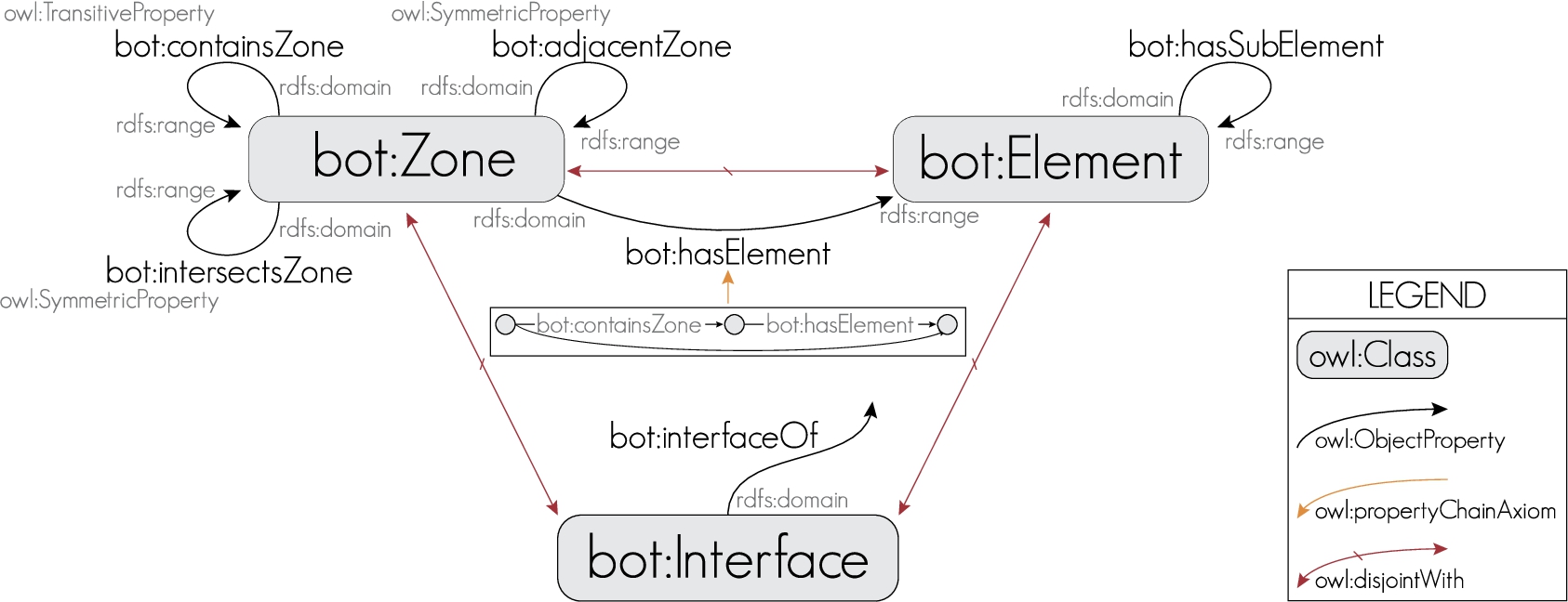
Illustration of the main three classes of BOT, which are pairwise disjoint, and the main properties used to link instances of these classes. The domain, range, and potentially transitive or symmetric aspect of object properties is illustrated. Objects of the bot:interfaceOf property typically are instances of bot:Zone or bot:Element. The property chain bot:containsZone ∘ bot:hasElement is a sub-property of the property bot:hasElement.
The difference between zone and element is common in the building and construction domain. An element is a concrete and tangible object whereas a zone is typically just air encapsulated by elements. In construction projects, spaces and zones are the physical frames for some functional requirements of the client (e.g. there is a need for a space that can facilitate two office workers with each their desk and with these requirements for the indoor climate). It is common practice to use these zones as placeholders for functional requirements even before they exist in the designed or the actual building. The functional requirements of the zones are translated by the designers into boundary conditions to technically equip these zones, which results in a number of physical building elements (e.g. number of ventilation terminals, work stations, lighting fixtures, hospital beds etc. and the specifications of these). It is therefore fundamental for anyone from the target audience working in the construction and related industry to have these concepts.
The version v0.3.1 of BOT described in this paper consists of 7 classes, 14 object properties, and one datatype property, with a Description Logics (DL) expressivity of

The high level terminology of the ontology is illustrated in Fig. 2. BOT has three main classes: bot:Zone, bot:Element, and bot:Interface required for CQs
As illustrated in Fig. 3 and required to cover
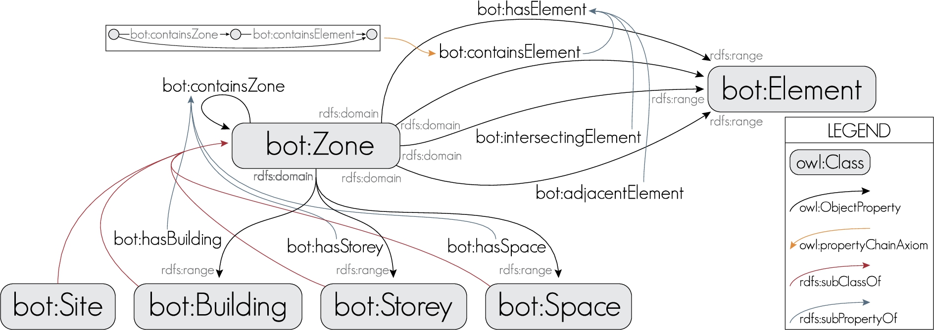
Illustration of the four sub-classes of bot:Zone and the three sub-properties of bot:hasElement. The domain and range of object properties is illustrated. The property chain bot:containsZone ∘ bot:containsElement is a sub-property of the property bot:containsElement.
A bot:Zone is defined as a part of the world that has a 3D spatial extent.14
This definition is inspired by the definition of Spatial Thing in the DOLCE Ultralite ontology [23].
is transitive, and links a zone to another one it fully contains. Three sub-properties of bot:containsZone are defined: bot:hasBuilding, bot:hasStorey and bot:hasSpace, whose ranges are bot:Building, bot:Storey and bot:Space, respectively. These properties can be used to group or subdivide zones as illustrated in Fig. 4, and cover
Zones in BOT follow a Matryoshka doll principle where one zone can be contained within another zone and so forth [58].
is symmetric, and links two zones that share part of their boundary (in the topological sense);
is symmetric, and links two zones whose 3D spatial extent is partly shared (e.g. a stair well intersecting several storeys).
bot:adjacentZone and bot:intersectsZone together cover
The classes of BOT can be used not only for existing buildings but can also be used to create requirements of a future building. For example, Rasmussen et al. [52] defines the client’s requirements for spaces of a future building as sub-classes of bot:Space.
A bot:Element is defined as a constituent of a construction entity with a characteristic technical function, form or position [
32
, Section 3.4.7]. Elements can host sub-elements, which is defined using the bot:hasSubElement property. This covers
Three main topological relationships between zones and elements are defined, so as to cover
links a zone to an element that shares part of its boundary;
links a zone to an element whose 3D extents is partly shared;
links a zone to an element it contains.
The latter property is used in a property chain axiom that formalises the fact that: if a zone contains a zone that contains an element, then it contains that element:
A super-property of these three properties, bot:hasElement, is defined to indicate a generic relationship between a bot:Zone and a bot:Element. The intended use of this relationship is not to be stated explicitly, but to be inferred from its sub-properties. It allows, for example, to query for all the doors of a building given that they have an adjacency to spaces contained in the building. Property bot:hasElement is also used in a property chain axiom that formalises the fact that: if a zone contains a zone that has an element, then it has that element:
Interfaces
The class bot:Interface is used to describe the relationship between some specific zones and elements in detail, and covers
the heat transmission area of the surface between a space and an adjacent wall can be used to determine the heat loss from that space through this wall;
Two interfaces between two zones and a wall. Interfaces can be used to qualify (i.e., attach additional information to) topological relationships between zones, elements, or zones and elements [58].
the localisation of the intersection between a pipe and a wall can be used to specify where to apply fire sealing;
the type of access between two zones can be used to specify access restrictions for use in indoor navigation.
An interface is assigned to elements or zones using the bot:interfaceOf property. The domain of that bot:interfaceOf is bot:Interface. Objects of the bot:interfaceOf property typically are instances of bot:Zone or bot:Element.
The last CQ
Any bot:Zone or bot:Element can be assigned a 3D Model (including geometry, material, etc.), using some existing data format for 3D models. Two properties are defined for this:
can be used if the 3D Model can be encoded as a literal. We encourage the use of URIs for mediatype descriptions with the IANA authority.15
IANA is the Authority responsible for registering mediatypes, among other.
can be used to link a bot:Zone or bot:Element to some URI that identifies a 3D Model. This 3D Model can then be described using some dedicated RDF vocabulary. Else, the 3D Model URI could be dereferenceable, and when looking up the URI one could retrieve a representation of the 3D Model with some existing data format for 3D models.
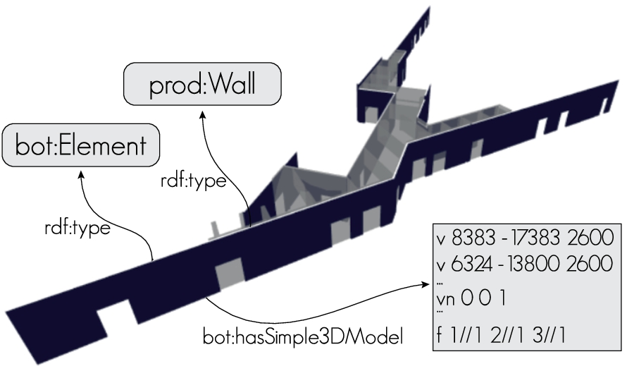
Bonsma et al. [13] discusses different considerations for describing complex geometry with ontologies, including references to the ontoBREP approach [50] and the ifcOWL approach [45]. Then the 3D model geometry, which is specified relative to the local coordinate system of the model, can be positioned in a global Geospatial Information Systems (GIS) context using the zero point of the site.
Figure 6 is a screenshot of a demonstration web-based software that renders a zone and its adjacent element instances in the browser. The 3D geometry of these zones and elements is a simple mesh geometry described using OBJ literal that is automatically extracted from a BIM authoring tool. This demonstration illustrates how existing web frameworks and libraries can be used out of the box to implement powerful solutions based on BOT, which may be used by users in the AECOO industry across the building lifecycle (see also Section 4). This demo implements functionalities that combine Linked Data and geometry.
Example of a graphical feedback from a request for all wall elements adjacent to a particular space using BOT terminology. The 3D model is described as an OBJ-formatted [22] mesh. A simple demo can be found online.16
BOT is designed to function as a central element in the interdisciplinary communication of the AECOO sector. In addition, it aims at being the key entry point to connect AECOO sector to adjacent domains. Moreover, alignments potentially allow to define automatic converters from datasets described with one ontology to another.
As there are numerous ontologies available in the AECOO domain we only describe two alignments in this paper: (1) the alignment to ifcOWL [48] a well accepted standard in the construction industry; and (2) to the DOLCE Ultralite upper ontology (DUL) [23], which is a foundational ontology meant to support broad semantic interoperability among domain-specific ontologies by providing a common starting point for the formulation of definitions.
Alignment to ifcOWL As a number of ontologies already exist in the construction domain, alignments of BOT to six commonly used domain ontologies are defined in [60,61]. The formal alignments are provided as separated ontologies.17
Alignment to the DOLCE ultralite ontology In addition to domain specific extensions, this work presents correspondences to upper ontologies such as DUL [23]. The concept bot:Zone and bot:Interface are specialised from dul:PhysicalObject, which is the concept in DUL of objects that are spatially located and have their proper space region. bot:Site is specialised from dul:PhysicalPlace meaning its location is inherent. bot:Building, bot:Storey, bot:Space and bot:Element, are specialised from dul:DesignedArtifact, which are physical artefacts described by a design. The object property bot:has3DModel is aligned to dul:hasRegion, and its range is further specialised to dul:SpaceRegion, which is the dimensional space that is used to localise the bot:Zone or bot:Element. Among object properties the following correspondences are defined:
bot:containsZone and bot:containsElement are specialised from dul:hasPart; bot:adjacentZone and bot:adjacentElement are specialised from dul:hasCommonBoundary; bot:intersectsZone, bot:intersectingElement, and bot:interfaceOf are specialised from dul:overlaps.
In this section, we overview how the BOT ontology can be used in combination with other ontologies.
Sub-typing BOT classes and properties
An external ontology can directly extend BOT defining sub-classes of BOT classes. Figure 7 illustrates one approach where the class fso:Heater from a fictive Flow Systems Ontology (FSO) is defined as a sub-class of bot:Element. From the explicit axioms illustrated with plain arrows in this knowledge base, a DL reasoner can infer that if inst:heater33 is of type fso:Heater, then it is also of type bot:Element, thereby giving it a more generic abstraction understandable by other domains.
BOT can also be extended with more specific properties. Figure 8 illustrates an approach where a new property fso:heatedBy is defined as a sub-property of bot:containsElement, and having range fso:Heater. From the explicit axioms illustrated with plain arrows in this knowledge base, a DL reasoner can infer that inst:spaceA2 contains inst:heater33, and that this element is of type fso:Heater.
Catalogues of products
An external ontology could define a catalogue of products including windows, walls, ducts or defibrillators. An instance of one of these classes can also be an instance of bot:Element. This can be explicitly asserted, or inferred from topological relations with other instances of bot:Zone or bot:Element. Figure 9 illustrates a knowledge base where an individual inst:prodABC is asserted to be an instance of the class product:Defibrillator, and to be contained in the zone inst:spaceA2. The dashed arrows illustrate the relationships that can be automatically inferred using DL reasoning.

Linking by defining sub-classes.

Linking by defining subClasses.
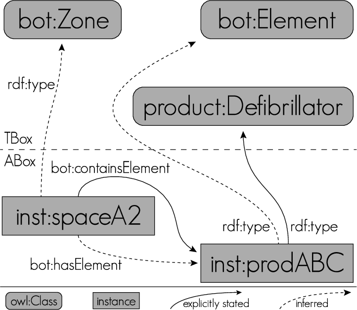
Example of an instance of both (1) a class defined in a hypothetical ontology of products, and (2) the bot:Element class. In this example relations illustrated using plain arrows are explicit, and relations illustrated using dashed arrows can be automatically inferred using DL reasoning.
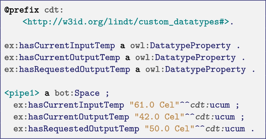
Different approaches for assigning values to the properties of some bot:Zone, bot:Element, or bot:Interface were discussed by Rasmussen et al. [55]. Assume one wants to assert that the input and output temperatures of a pipe are currently 61.0°C and 42.0°C, but the requested output temperature of that pipe is 50.0°C.
The most simplistic form (L1 in [55]) consists in directly linking the pipe to each of its temperature values, described as literals or as individuals. For example, the snippet below defines the three temperatures using the Custom Datatypes (CDT) Unified Code for Units of Measure (UCUM) datatype [39].
The snippet below represents the same knowledge but using the QUDT ontology [27].

These approaches cannot describe the context in which the value assignment holds. It is not explicit that there are two different values for the same property and another value for another property.
A more flexible approach, relying on specific properties as described in the SOSA/SSN standard [28], consists in using ex:Temperature as a class, and associating two different instances of that class to the pipe (the input and output temperature) using different properties (ex:hasInputTemperature and ex:hasOutputTemperature). The snippet below illustrates this approach using SOSA/SSN, SEAS [37], and the CDT UCUM datatype.

Class level properties
Some properties are not suitable for being asserted at instance level. For example, a specific space holds a set of functional and technical requirements that are valid for all instances and a specific type of element such as a project specific brick wall is a container for properties that are valid for all instances of this wall, e.g.: thermal properties, structure etc. Properties like these can be defined as OWL property restrictions. The snippet below shows a project, manufacturer or company specific wall which is defined by property restrictions on its thickness and U-value. The snippet also describes three instances of this wall which all have individual surface areas.

Existing BOT implementations
Primary implementations of BOT are reported by Bonduel et al. [10] in datasets, web-applications, or AECOO application plug-ins.
Manual creation of BOT datasets To model existing buildings, one may manually create an ontology that imports BOT. This approach is proposed in [11] and was experimented by different researchers in the W3C LBD CG group while developing BOT. Dedicated user-interfaces could be developed for this, potentially relying on RDF libraries. However, users in the AECOO industry usually use building modelling applications, which implement functionality to export the model as an IFC document.
Export of BOT datasets from IFC documents A converter from IFC documents to BOT, named IFCtoLBD converter, has been developed in the community18
Plug-in for the Revit building modelling application Rasmussen et al. [54] reports on the development of a plug-in for the Revit BIM authoring tool, which leverages the .NET API to export building topology data to a triplestore.19
Javascript library for visualising and querying buildings in the browser Rasmussen et al. [54] also reports on the development of a JavaScript library, which can be used to visualise and access building data in the browser.20
Demo

The infrastructure from triple extraction over the web API to pushing data to the triplestore.

Visualisation and manipulation of BOT and SOSA/SSN data in the browser. (Illustration from [53].)
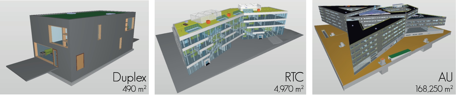
The three BIM models (Duplex Apartments
Towards a BIM Maturity Level 3 linked-data-based CDE in the browser Figure 10 shows the overall process of getting data from a BIM authoring tool to a triplestore, from where a web application (Fig. 6) reads the data. Then, the JavaScript library can combine this data with other sources (i.e. a linked data based CDE). Figure 11 illustrates a demonstration presented in Rasmussen et al. [53], where this library is further extended to integrate building models and sensor observations using SOSA/SSN, allowing to visualise the history of the environmental factors in the browser when clicking on a space, or colouring the spaces according to their current ambient temperature.21
Demo –
Comparison of the building model exports for the Duplex Apartments
We already justified throughout Section 3 that the competency questions listed in Section 3.1 are covered by the classes and properties in the BOT ontology. This section provides a supplementary evaluation of BOT on two aspects. Section 5.1 compares the Revit native and IFC exports with the output of the Revit export plug-in introduced in Section 4.5. Then Section 5.2 provides some insight on the BOT reasoning capabilities. Figure 12 illustrates the BIM models on which the evaluations are performed:
The RDF export of
Table 1 summarises the comparison of the exports of (1) the native Revit documents, (2) the IFC STEP Physical File (SPF) documents, and (3) the RDF 1.1 Turtle documents using the Revit exporter plugin introduced in Section 4.5.
The native Revit files are the biggest and are already very well compressed. IFC files are 1.4
The export times are evaluated on 5 consecutive exports. Approximately half of the time is dedicated to the generation of geometry (08′36″ on average for
The plug-in currently does not export all of the BOT axioms that could be exported. For example adjacent elements are only extracted for walls. Some topology relationships are deduced from the native geometry, while they could be deduced from the OBJ objects. The plug-in currently exports a limited set of element product classes (Revit types catalogue, c.f., Section 4.2), and a limited set of properties as simple datatype properties with no units (c.f., Section 4.3). 3D models of zones and elements are exported as mesh geometry OBJ literals, loosing in the process the information regarding the construction process of the geometry.24
Building model software keep track of the operations used to construct the building. For example, (1) define a certain plan, (2) create a point given some coordinates, (3) create a circle in the plan having this point as a centre and a certain radius, (4) extrude the circle along the normal of the plan for a certain length, (5) remove the intersection of the obtained cylinder from another solid, etc.
Number of results and query execution times for entailment regime
In this section we report on the evaluation of six queries that require reasoning capabilities on each of the three building model RDF datasets.
Select zones (therefore also sites, buildings, storeys, spaces):

Select zones contained in a storey (therefore also the spaces this storey has):

Select zones contained in a site (therefore also those transitively contained in the site):

Select elements contained in a site (therefore also those contained in the zones it contains):

Select the elements that a site has (therefore also the elements contained in, adjacent to, or intersecting, a zone it contains):

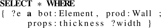
Select the thickness of each wall.
Each query is executed after loading the model in a freshly started Stardog25
triplestore v5.2.2 to disregard caching optimisation. The process is repeated 10 times to establish mean values.Table 2 lists the number of results, and the query execution times in milliseconds for entailment regimes (1)
The Industry Foundation Classes (IFC) standard is the de-facto standard for the file-based exchange of building models between Building Information Modelling (BIM) authoring tools, but there is a need in the Architecture, Engineering, Construction, Owner and Operation (AECOO) industry to evolve to BIM Maturity Level 3, which in essence identifies interoperable and distributed web-based interdisciplinary communication in the AECOO industry. The World Wide Web Consortium (W3C) Linked Building Data (LBD)-Community Group (CG) vision is that the Linked Data (LD) models and best practices can be leveraged for this purpose. In this article, we introduced the Building Topology Ontology (BOT) as the first stable output of this group, and illustrated how BOT is envisioned to be used in combination with other ontologies that describe product catalogues, sensor observation, or IoT devices. We have reported on the current implementations of BOT, and evaluated the export of BOT-compliant Resource Description Framework (RDF) datasets using three native BIM models. The combined use of BOT, existing web-compliant geometry formats, and other ontologies, has been demonstrated in web-based applications. Basic query execution times of less than a second on a building of more than 150,000 m2 demonstrate that using queries over BOT datasets should be suitable for implementing a web-based Common Data Environments (CDEs), thus largely improving the productivity in an AECOO industry where information exchange is currently handled in a predominantly manual, labour-intensive, and error-prone manner.
Although BOT does not alone cover the four general requirements for BIM Maturity Level 3 listed in Section 1, we share the W3C LBD-CG vision that using Linked Data technologies and an open set of well defined ontologies such as BOT is a good direction to be undertaken. In fact:
Using (HTTP) URLs as identifiers for things and making sure that these things are described when looking up those URLs (the three first principles of Linked Data), directly enables information to be exchanged on the Web.
The Web is already used as an information hub for many collaborative, web-based workflows among interdisciplinary stakeholders, not only in the AECOO domain.
The W3C recommendation on Data on the Web Best Practices directly prescribes the use of “terms from shared vocabularies, preferably standardized ones, to encode data and metadata.” [41]. Semantic Web technologies are interoperable, flexible, and open, and BOT and other standard and non-standard ontologies can be jointly used to cover different domains.
RDF and the existing ontologies, together with the Linked Data principles, can be used to integrate, for example, building models with openly available datasets (e.g. material property datasets or weather data), and applications (e.g. Geospatial Information Systems (GIS) or Facility Management).
In the future, we will continue to improve BOT, its support in BIM authoring tools and web browser applications, and its integration with other ontologies and datasets. In terms of ontology maintenance the competency questions will be continuously updated. Potential revisions include more detailed topological modelling as introduced by the Region Connection Calculus (RCC) [51]. BOT will be the basis of the development of the W3C LBD CG, which will focus on the interoperable and decentralised web-based description of products and properties, and the homogeneous use of building models across the building life-cycle.
Footnotes
Acknowledgements
After the initial release, BOT is developed continuously as a community effort by the W3C LBD CG. The authors are very thankful for the rewarding discussions in this forum, in the Linked Data in Architecture and Construction (LDAC) workshops and would like to clearly acknowledge all received inputs. We would like to thank Mathias Bonduel (@mathib) and Lucas Verhelst (@LucasVerhelst) as well as the other CG members that have provided human readable labels and comments in their mother tongue to BOT. We would like to thank the reviewers Simon Scheider, Yingjie Hu, and Tomi Kauppinen, for their valuable feedback towards improving this paper, and also Antoine Zimmermann and Iker Esnaola-Gonzalez for their constructive comments ![]() . Part of the work on BOT has been funded by the NIRAS ALECTIA Foundation and Innovation Fund Denmark, the initiative Mittelstand 4.0 by the German Federal Ministry for Economic Affairs and Energy, the French ANR OpenSensingCity project, and ENGIE.
. Part of the work on BOT has been funded by the NIRAS ALECTIA Foundation and Innovation Fund Denmark, the initiative Mittelstand 4.0 by the German Federal Ministry for Economic Affairs and Energy, the French ANR OpenSensingCity project, and ENGIE.