
Abstract
In the component operated at elevated temperatures, the life evaluation should be made in consideration of both creep and fatigue (creep-fatigue) such as the linear damage summation rule. However, the concept of creep-fatigue life evaluation has not spread well in the industry. In order to consider the reason, a series of past creep-fatigue research was surveyed, namely experimental methods, life evaluation procedures and strength design guidelines. As a result, it was revealed that the mechanism of creep-fatigue interaction has not been fully clarified yet, which results in obscuring the necessity of creep-fatigue life evaluation. The necessity of creep-fatigue life evaluation was reviewed and consequently it proved to be necessary in two cases. One is the case where the creep-fatigue interaction is significant for some kinds of material, loading modes and temperatures. The other is one where the amount of creep damage is almost the same as that of fatigue damage even though the creep-fatigue interaction is insignificant.
Keywords
Introduction
Most components operated at elevated temperatures are subjected to the cyclic loading (i.e. fatigue) due to startup-shutdown and constant loading (i.e. creep) due to the steady operation. This is true not only for large equipment such as a power plant but also small devices such as a personal computer. Therefore, it seems to be reasonable to apply the concept of creep-fatigue life evaluation to those equipment and devices.
In Japan, a lot of research on creep-fatigue has been carried out from the 1970s to 1980s. This was mainly done to establish the strength design of the fast breeder reactor (FBR). The thermal stress is dominant in FBR components as shown in Fig. 1 [8]. Table 1 shows the comparison of fracture mode and strength design in between FBR and power boiler operated at similar temperatures. While the main fracture mode is creep due to hoop stress in power boiler piping where high pressure steam flows, it is creep-fatigue due to thermal stress in FBR piping where low pressure liquid sodium flows. A series of creep-fatigue tests were performed and some creep-fatigue life evaluation procedures were proposed based on test data. Finally, the strength design guideline on creep-fatigue was developed for FBR components.
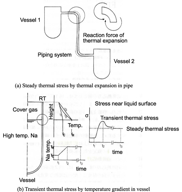
Thermal stress in FBR component [8].
Comparison of fracture mode and design in FBR and boiler
However, the concept of creep-fatigue life evaluation has not spread well in the industry. It’s a common belief that either creep or fatigue life evaluation are made for the component operated at elevated temperatures. The most important reason may be that the necessity of creep-fatigue life evaluation is not fully recognized. The mechanism of creep-fatigue interaction has not been fully clarified yet, which seems to result in obscuring the necessity of creep-fatigue life evaluation. For example, it’s not very easy to judge the necessity of creep-fatigue life evaluation for the strength design of Ni-based piping which is the candidate material in advanced USC power boiler system.
Therefore, in order to consider the necessity of creep-fatigue life evaluation for the component operated at elevated temperatures, a series of past creep-fatigue research were reviewed, namely experimental methods, life evaluation procedures and strength design guidelines.
Loading waveform
One of the typical loading waveforms of the creep-fatigue test is a trapezoidal wave accompanied by tensile strain holding or load holding. The other is a triangle one under low strain rate or load rate. They simply simulate the loading patterns which are supplied to components in the field. Their purposes are to examine the reduction of pure fatigue life by the creep effect introduced during strain holding or low strain rate. Among these loading waveforms, the strain controlled trapezoidal one accompanied with tensile strain holding is most widely used to acquire the creep-fatigue data. The first reason is that the thermal stress supplied to components in the field is strain controlled as shown in Fig. 1. The second one is that the creep effect does not appear with compressive strain holding. The third one is that the tensile load holding has the problem of causing rachet deformation in the tension side.
Example of fatigue test result with tensile strain holding
The first example is the fatigue test results with tensile strain holding of Gr.91 steel at 600 °C as shown in Fig. 2 [5]. Strain range is 0.4% to 1.5% and strain hold time is 1 to 60 min. It was revealed that the fatigue life was reduced by tensile strain holding in any strain range. Fatigue life reduction factor which is the ratio of creep-fatigue life to pure fatigue one was a minimum of about 0.4. It was larger as the strain range was lower. As the time of strain holding was longer, it was also smaller, although it tended to be saturated.
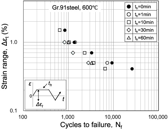
Creep-fatigue test results of Gr.91 steel at 600 °C [5].
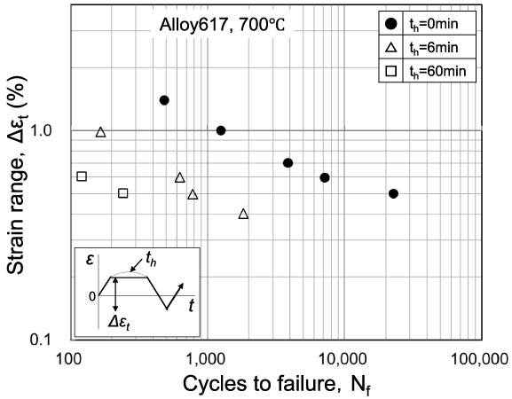
Creep-fatigue test results of Alloy 617 at 700 °C [2].
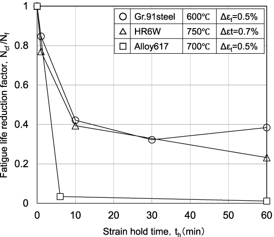
Comparison of fatigue life reduction factor.
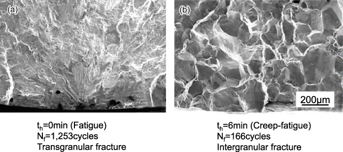
Fracture surface of Alloy 617 (700 °C, Δ𝜀t = 1%) [1].
The second example is the fatigue test results with tensile strain holding of Alloy 617 at 700 °C as shown in Fig. 3 [2]. Strain range is 0.4% to 1.4% and strain hold time is 6 or 60 minutes. Fatigue life reduction by tensile strain holding of Alloy 617 was significant compared with that of Gr.91 steel. Fatigue life reduction factor was about 0.01 at the strain range of 0.5% and the strain hold time of 60 minutes.
Figure 4 shows the comparison of fatigue life reduction factors among Gr.91 steel at 600 °C and HR6W steel at 750 °C [3] and Alloy 617 at 700 °C. Fatigue life reduction factor of Alloy 617 was much smaller than that of Gr.91 steel or HR6W steel. Fatigue life reduction factors of three kinds of materials similarly tended to be saturated at relatively short strain holding. Incidentally, Fig. 5 [1] shows the facture surface of Alloy 617 observed with SEM where the reduction of fatigue life by strain holding was most significant. Fracture mode was made the transition from trans-granular to inter-granular by relatively short strain holding.
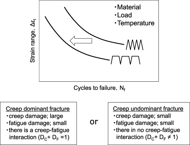
Fatigue test with tensile strain holding is to examine how much fatigue life will be reduced by strain holding immediately. However, the ultimate purpose is to clarify the creep-fatigue interaction through the investigation of fracture mode and the estimation of creep-fatigue damage. For example, when fatigue life is significantly reduced by strain holding, as shown in Fig. 6, two cases will be assumed as follows: Case of creep dominant fracture There is no creep-fatigue interaction as the amount of creep damage (D
C
) is large and that of fatigue damage (D
F
) is small (D
C
+ D
F
= 1). Case of creep undominant fracture There is a creep-fatigue interaction as the amount of creep damage (D
C
) is small and that of fatigue damage (D
F
) is also small (D
C
+ D
F
≠ 1).
Indication of significant fatigue life reduction by strain holding.
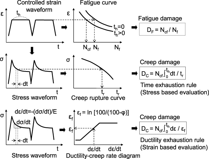
Evaluation procedures of fatigue damage and creep damage.
Linear damage summation rule
Fatigue is a cycle-dependent damage, while creep is a time-dependent damage. Linear damage summation rule [6,7] is the way to evaluate the cree-fatigue life by linearly summing fatigue damage and creep one accumulated until failure. Figure 7 shows evaluation procedures of the fatigue damage (D F ) and the creep damage (D C ). The expression of D C + D F = 1 means that there is no creep-fatigue interaction, while that of D C + D F ≠ 1 means that there is a creep-fatigue interaction. As for the creep damage, there are two kinds of evaluation procedures, as outlined below.
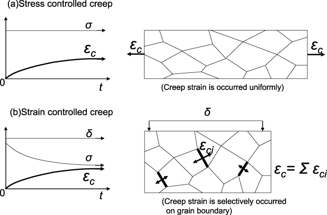
Difference between stress controlled creep and strain controlled creep [4].
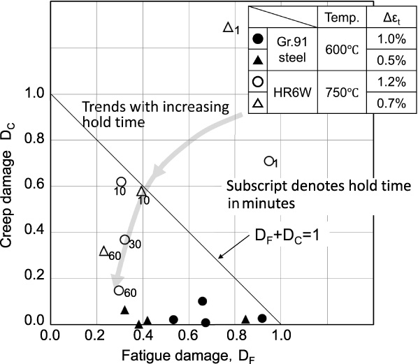
Time exhaustion rule is the way to evaluate the creep damage based on the stress, as shown in Fig. 7. Figure 8 shows the results of creep-fatigue life evaluation for Gr.91 steel at 600 °C [5] and HR6W steel at 750 °C [3] where the creep damage is evaluated by the time exhaustion rule. Data of HR6W was approximately plotted near the line of D C + D F = 1, while that of Gr.91 steel was quite far from that of D C + D F = 1 as most creep damage was very small below 0.1. There may be two kinds of views on the result of creep-fatigue life evaluation for Gr.91 steel. One view is that there is a creep-fatigue interaction if the creep damage is appropriately evaluated. The other one is that the creep damage is evaluated too conservatively. The latter view may be due to the difference of damage mode between the stress-controlled creep and the strain-controlled one as shown in Fig. 9. Creep strain is occurred uniformly in the stress- controlled creep, while it selectively occurred on the grain boundary in the strain controlled creep [4]. Therefore, the creep damage occurred in the strain-controlled creep-fatigue test may not be appreciated by the time exhaustion rule which is based on the stress-controlled creep rupture curve as shown in Fig. 7.
Evaluation of creep damage by ductility exhaustion rule
Ductility exhaustion rule proposed in UK is the way to evaluate the creep damage based on a strain as shown in Fig. 7. It defines the creep damage as the exhaustion of creep ductility which depends on a creep rate. Figure 10 [5] shows the re-evaluation results of the creep damage for Gr.91 steel shown in Fig. 8 by the ductility exhaustion rule. Time exhaustion rule evaluated the creep damage very small, while ductility exhaustion rule evaluated the creep damage appropriately and so the data was approximately plotted near the line of D C + D F = 1. However, the validity of this results should be verified, because the creep ductility in a lower creep rate is not an experimental value but an extrapolated one which has a considerable influence on the results of creep damage evaluation as shown in Fig. 7.
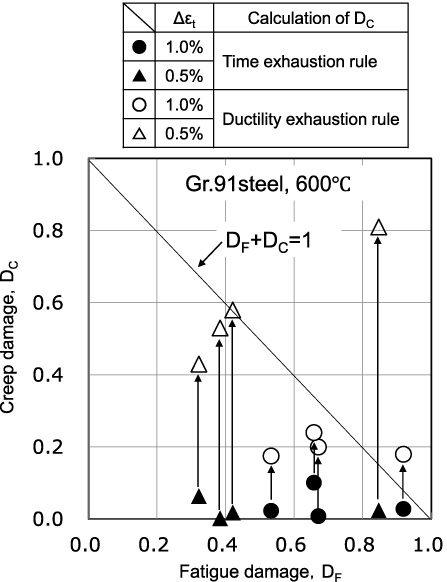
Evaluation of creep damage by ductility exhaustion rule [5].
As already mentioned, there may be two kinds of views on the result of creep-fatigue life evaluation for Gr.91 steel shown in Fig. 8 [5]. One view is that there is a creep-fatigue interaction. The other one is that the creep damage is evaluated too conservatively. According the latter view, a considerable research has been made until now in order to improve the procedures of creep damage evaluation. Meanwhile, there are few researches to clarify the mechanism of creep-fatigue interaction.
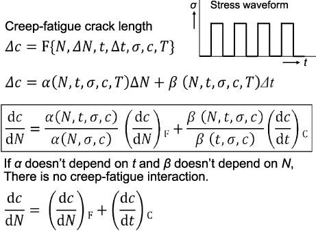
Analysis procedure of creep-fatigue interaction [9].
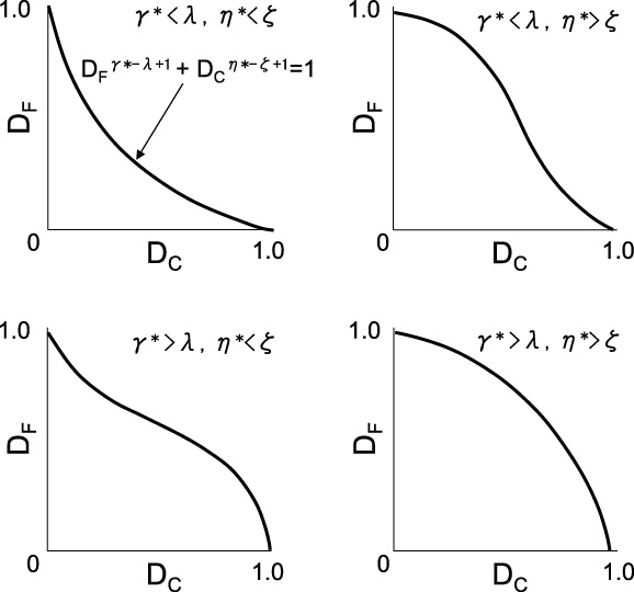
Four types of creep-fatigue interaction [9].
Yokobori et al. tried to treat creep-fatigue issues not as an individual combination of creep and fatigue but as a simultaneous progress of a time-dependent fracture and a cycle-dependent fracture [9]. Figure 11 shows the procedure of creep-fatigue analysis. An increase rate of creep-fatigue damage is expressed as a linear summation of creep crack growth rate and fatigue one. The term of fatigue crack growth is multiplied by a time dependent coefficient and similarly that of creep crack growth is multiplied by a cycle-dependent coefficient. If a coefficient, 𝛼 does not depend on time, t and coefficient, 𝛽 does not depend on cycle N, there is no creep-fatigue interaction (D C + D F = 1). Figure 12 shows four types of creep-fatigue interaction which depend on the combination of coefficient, 𝛼 and 𝛽. A correspondence between these coefficients and the material properties should be verified in future.
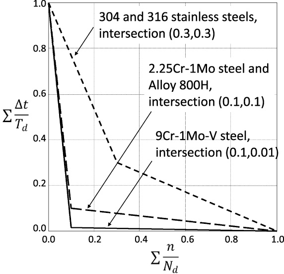
ASME creep-fatigue damage envelope.
Linear damage summation rule is adopted in ASME design code where the creep damage is evaluated by the time exhaustion rule. Figure 13 shows creep-fatigue damage envelopes for several materials. They mean the allowable limitations of creep-fatigue damage which are drawn based the lower limit of experimental data obtained from some creep-fatigue tests. They consist of two straight lines with intersections. For example, the coordinates of intersections, (D F , D C ) are (0.3, 0.3) for Type 304 or 316 stainless steels, (0.1, 0.1) for 2.25Cr-1Mo steel or Alloy 800H and (0.1, 0.01) for 9Cr-1Mo-V steel (i.e. Gr.91 steel). Incidentally, the damage envelope of Gr.91 steel in Fig. 13 almost corresponds to the experimental data shown in Fig. 8. Although the time-exhaustion rule might evaluate creep damage too conservatively, the safety is ensured by taking the lower limit of experimental data.
Necessity of creep-fatigue life evaluation
The concept of creep-fatigue life evaluation has not spread well in the industry. It’s a common belief that either creep or fatigue life evaluation is made for the component operated at elevated temperatures. However, some creep-fatigue damage is often observed in many failure cases of components. It may suggest that there is a possibility to prevent a failure by adopting creep-fatigue strength design.
It has not been clarified in previous research under what conditions (material, load, temperature) creep-fatigue life evaluation will be required. It seems to be necessary in two cases as shown in Fig. 14. In case 1 the creep-fatigue interaction is significant. In this case, we should be careful that components will lead to failure even if the sum of creep damage and fatigue damage is smaller than 1. In case 2 the amount of creep damage is almost the same as that of fatigue damage although there is no creep-fatigue interaction. In this case, either creep design or fatigue design will be possible to overestimate the life of components.
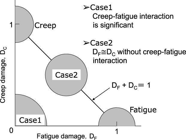
Two cases where creep-fatigue evaluation is needed.
The concept of creep-fatigue life evaluation has not spread well in components operated at elevated temperatures as either creep design or fatigue design seems to meet the requirements. However, several failure analyses suggest that there is a possibility to prevent a failure by adopting creep-fatigue strength design. Most of previous research may be to improve the procedures of creep damage evaluation, while there are few studies to clarify the mechanism of creep-fatigue interaction. The mechanism of creep-fatigue interaction has not been fully clarified yet, which seems to result in obscuring the necessity of creep-fatigue life evaluation. Creep-fatigue life evaluation seems to be necessary in two cases. One is where the creep-fatigue interaction is significant. The other is where the amount of creep damage is almost the same as that of fatigue damage though there is no creep-fatigue interaction.
Footnotes
Conflict of interest
None to report.