At the Forschungs-Neutronenquelle Heinz Maier-Leibnitz (FRM II) of the Technical University of Munich (TUM) a new source for ultra-cold neutrons (UCN) with a solid deuterium converter is currently under construction. This summary paper shall give an overview of the project and its current status. Research results concerning converter preparation, para-to-ortho conversion, radiation effects and neutron transport, which have been achieved in the last years, are presented and their relevance and transferability for the design of a future UCN source at the European Spallation Source (ESS) are discussed.
Precision experiments with ultra-cold neutrons [37,63], such as the search for a possible electric dipole moment (EDM) of the neutron [1,46,54] or the measurement of the lifetime of the free neutron [6,16,25,45,47,52,56], require high UCN densities. Stronger UCN sources are presently developed worldwide, based on the principle of superthermal UCN production, using cryo-converters made of solid deuterium () or superfluid helium [4,10,18,23,24,30–32,34,35,38,39,48,57,58,72,73]. At the FRM II a UCN source with a converter and premoderator, placed in a distance of from the central fuel element inside the horizontal, through-going beam tube SR6, is currently under construction. It is supposed to generate UCN densities of in up to four connected experiments.
Design of the UCN source at the FRM II
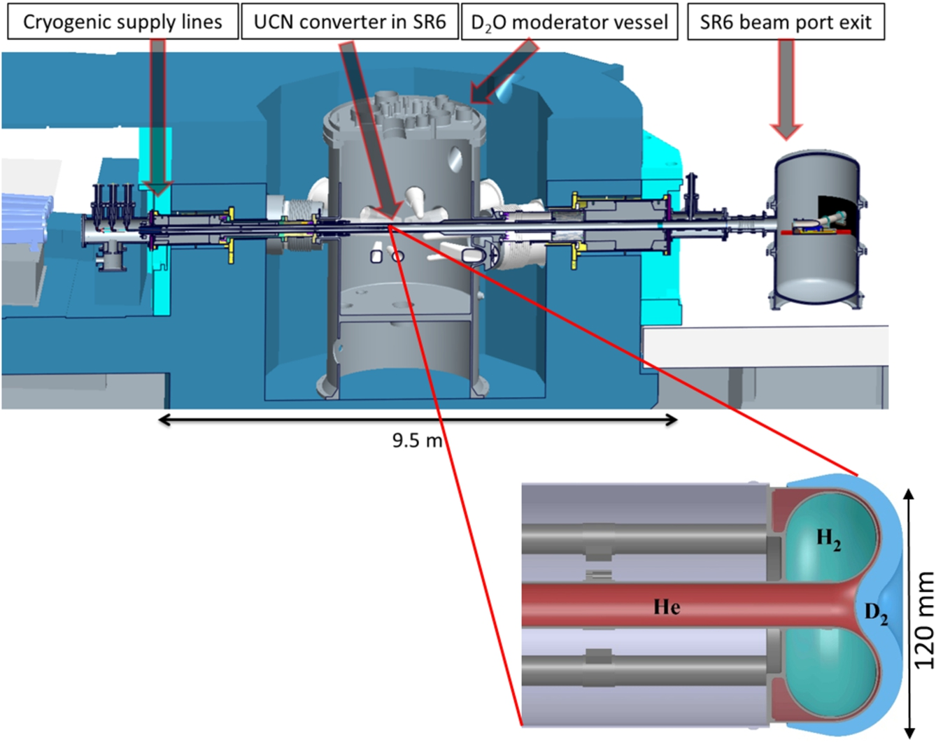
At the FRM II the through-going beam tube SR6 is currently unused. It has one beam port exit at the east side of the experiment hall (called A-side), and one beam port exit in the neutron guide tunnel at the west side (called B-side). This offers the possibility to install all necessary cryogenic supply lines from the B-side, and thus the A-side is completely free for undisturbed extraction of the UCN to connected experiments. The position and the layout of the UCN source is depicted in Fig. 1.
Top: vertical cut view of the heavy water vessel and the surrounding concrete shielding (indicated by blue color) of the FRM II along the SR6 beam axis. The cryogenic supply lines for the UCN converter are installed from the left (called B) side. UCN can be extracted to the opposite SR6 A-side through a safety vessel to connected experiments. The UCN converter is placed approximately in the middle of the SR6 beam tube, in a distance of from the central fuel element of the FRM II. Bottom: vertical cut view of the UCN converter, a double-walled, toroidal-shaped aluminium vessel. Both walls are cooled by a closed supercritical helium cooling loop (indicated by red color) to a temperature of . Inside the vessel solid hydrogen as premoderator is frozen out (indicated by green color), and the solid deuterium converter (indicated by blue color) is resublimated from gas to solid state to the outer wall of the aluminium vessel.
The central part of the UCN source is the converter vessel, a double-walled toroidal-shaped aluminium cap piece, which is cooled by a continuous flux of a closed supercritical helium cooling loop. The necessary cooling power of up to at is supplied by two cold boxes (AirLiquide Helial 2000) to the closed supercritical He-loop. The converter contains of solid hydrogen () as premoderator (volume ) to precool the incoming thermal neutron flux () to an effective neutron temperature of . The UCN converter (maximum amount ) is frozen to the outer surface of the converter vessel by resublimation of gas to the solid phase. The premoderated incoming neutrons can enter the converter, where they induce solid-state excitations (mainly phonons) of the crystal lattice or rotations of the molecules. Solid ortho-deuterium has exited states in the energy range of . If the kinetic energy of an incoming neutron equals the energy of a solid-state excitation, the incoming neutron can lose practically its total initial energy, and is converted into the energy regime of ultra-cold neutrons [19]. The UCN generated by this process can leave the converter, and are guided to the SR6 beam port exit in the experiment hall, and fed into connected experiments. The expected UCN flux density at the SR6 A-side beam port exit is within the energy range of and a beam aperture of [17].
Solid deuterium as UCN converter material
Para-to-ortho conversion
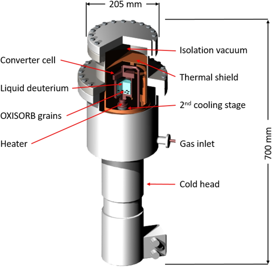
Since the inelastic up-scattering cross-section for UCN on para-deuterium is about a factor of 150 higher than that of ortho-deuterium at [36], an efficient para-to-ortho conversion is a prerequisite to keep the UCN lifetime in the converter material close to its optimum value at about . Natural thermal conversion of para-to-ortho state in takes months [60]. Therefore, we use OXISORB® [67] (chromium oxide bound in silica grains) as paramagnetic catalyst to accelerate the spin-flip process in a separate cryogenic cell. A detailed description of the process can be found in ref. [12]. The OXISORB® is cooled by a separate two-stage Gifford–McMahon cryo-cooler, with a cooling power of at . It turned out that conversion temperatures just above the triple point () are optimal for our purpose, since deuterium from the liquid phase can be boiled to provide close contact of the molecules with the surface of the catalyst. With this method it could be shown that the conversion rate can be enhanced up to values of [17]. The residual population of the para state is characterized by the para-to-ortho transition energy () and the Boltzmann factor , resulting in a concentration of about 1% in the low-temperature limit of . The ratio of to is determined off-line by means of a Raman spectrometer, using a small sample of deuterium gas which is extracted by warming up the frozen deuterium. A para-concentration of could be confirmed in all measurements. A scheme of the converter unit is shown in Fig. 2.
Scheme of the para-to-ortho converter using the surface contact of liquid deuterium with OXISORB® grains. The converter cell is mounted on the cooling stage of the cryo-cooler, while the thermal shield is cooled by the stage.
Converter preparation
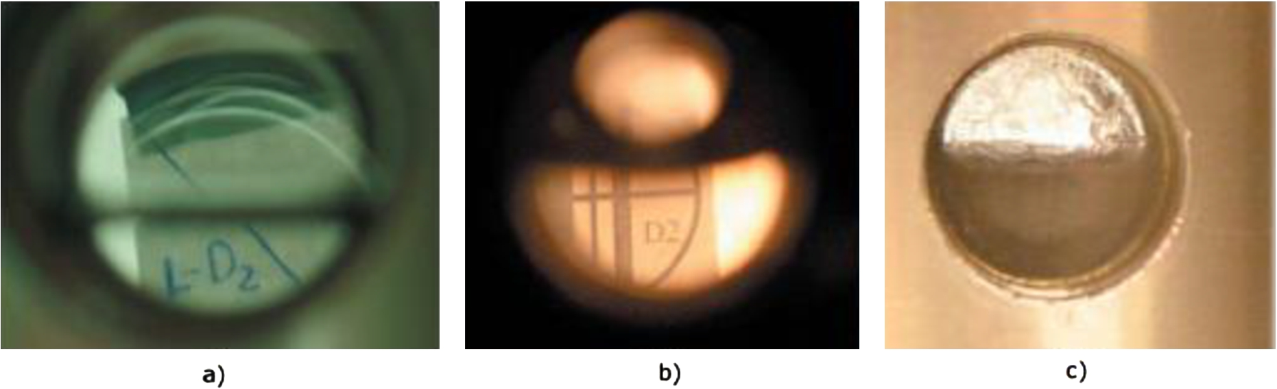
The preparation of an optically transparent converter crystal is an important task to avoid additional losses of UCN due to scattering on inhomogeneities, such as grain boundaries. Solid deuterium can be frozen out either from the liquid or directly from the gaseous phase via resublimation. Due to the horizontal geometry of the FRM II UCN source, freeze-out via resublimation is the only possible way for preparation of the converter. To study all important parameters which influence the crystal quality, such as temperature and temperature gradients, pressure, speed of freeze-out and incoming mass flow of gaseous deuterium, an aluminium sample cell with an inner volume of equipped with windows made of sapphire glass was mounted on a two-stage Gifford–McMahon cryo-cooler. With a heater at the second stage and a LakeShore temperature controller it was possible to adjust the cell temperature from to . It was possible to create optically transparent crystals by resublimation at temperatures when the incoming flow of deuterium gas was . Pictures of crystals generated under different conditions are depicted in Fig. 3. A detailed description of the setup and the freeze-out procedures can be found in ref. [41].
a) Solid deuterium frozen out from the liquid phase. b) Solid deuterium frozen out via resublimation from the gaseous phase at with an incoming gas flow of . c) Solid deuterium frozen out via resublimation from the gaseous phase at with an incoming gas flow of .
After these preliminary investigations, a prototype of the converter vessel of the FRM II UCN source has been cooled with liquid helium down to a temperature of in a test setup and the freeze-out process via resublimation has been studied. Also here optically transparent deuterium crystals could be produced when the incoming gas flow was . A detailed description of these experiments can be found in ref. [68].
Radiation-assisted para-to-ortho conversion
Besides by catalytic materials, the ortho-fraction in deuterium can also be increased by irradiation. It is well established that atomic deuterium produced by radiation effects is responsible for the transition in deuterium [7,13,50,59,62]. Atomic deuterium is paramagnetic, because of its unpaired single electron. Thus, it provides the necessary magnetic moment to flip nuclear spins of the surrounding molecules.
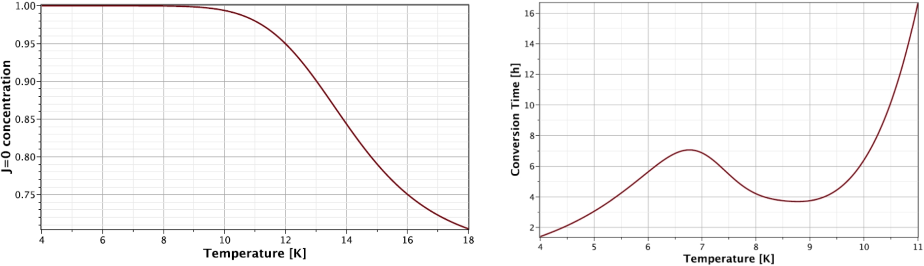
Any kind of radiation, be it neutron, γ or β radiation, will ionize the deuterium either directly through electromagnetic interactions or indirectly by first colliding with an atom, which then causes ionization. The main ionization processes in deuterium are [62] Lower energetic particles may also excite the electronic system of the deuterium without ionizing it, leading to the reactions The reactions (1)–(7) are leading to 1.14 directly formed atoms per created ion pair. Since is only stable in high vacuum, it will convert to via the reaction This leads to another free deuterium atom, now formed indirectly. The ions will at some point recombine with an electron according to the reaction This reaction is the main source of atomic deuterium under irradiation. On average there will be atoms created per ion pair. Even though this value has been determined in hydrogen gases, experiments have shown that it still holds true in solids. Taking into account the molecular break-up of deuterium, transitions between para and ortho deuterium, and recombination of deuterium atoms to molecules, a differential equation can be set up to calculate the content in deuterium under irradiation. Its solution, for the conditions of the FRM II UCN source, has been proven experimentally, see ref. [69]. As a result, Fig. 4 shows the ortho concentration in the FRM II UCN source for the case as well as the expected conversion time constant. One can see that up to the deuterium will be almost completely in its state. For higher temperatures there is a sharp drop almost down to the high-temperature equilibrium values of the ortho concentration. The atoms recombine too quickly and the newly formed molecules will have the high temperature equilibrium ortho concentration. At temperatures below the conversion rate is higher than the recombination rate of the atoms, while at higher temperatures the recombination rate exceeds the rate by several orders of magnitude, e.g., by five orders at .
Left: the concentration for the case in the FRM II UCN source depending on the temperature. Up to the deuterium will be completely in its ortho state. At higher temperatures the ortho concentrations drop rapidly towards the high temperature equilibrium due to the recombination of deuterium atoms. Right: calculated conversion time constant for a deuterium crystal under irradiation with a dissociation rate of as expected for the FRM II UCN source. Both figures from [69].
UCN transport
The efficient transport of UCN from their source to the experimental site is a major issue for various kinds of precision experiments. Neutron guides often have to transport the UCN several tens of meters with acceptable losses. At the FRM II a site dedicated to investigations with UCN is foreseen in an external experimental hall about away from the new UCN source. The site offers an environment adequate for precision experiments, in terms of disturbing mechanical vibrations, magnetic fields, electromagnetic noise and radiation.
UCN can be guided by total reflection in tubes either made of a suitable neutron reflecting material or coated with such a material. The transport is accompanied by many wall reflections and hence the loss probability per wall collision is an important quantity [3,11,14,15,28,33,40,42,43,49,53,61,64,66,71], as well as transport losses by diffuse reflection. As known, for a rough surface the probability of diffuse scattering is approximately given by [42,49,64], where is the average surface roughness and λ the UCN wavelength. Therefore the roughness should be in the order of or better, to decrease the probability of diffuse reflection to below 1%. In addition, for a multi-purpose UCN guide system the neutron optical potential should be as high as possible, especially for a solid deuterium UCN source () as it is planned at the FRM II.
One possibility to produce UCN guides with low surface roughness and high neutron optical potential is to fabricate foils via the replication technique (replica guide), which is already used for many years at the Institut Laue-Langevin (ILL) UCN facility [65]. The surface exposed to the UCN is a copy of a float glass surface, onto which a Ni-alloy is deposited by sputtering, reinforced by natural nickel by a galvanic process, and then removed as a foil. For a Ni-alloy replica surface investigated by Plonka et al. [49] the surface roughness was less than and the UCN transport losses by diffuse reflection, absorption or up-scattering were measured to be less than per reflection. Together with the high neutron optical potential of or even (, ) [51] those guides are well suited to transport UCN over a longer distance to a multi-purpose experimental site.
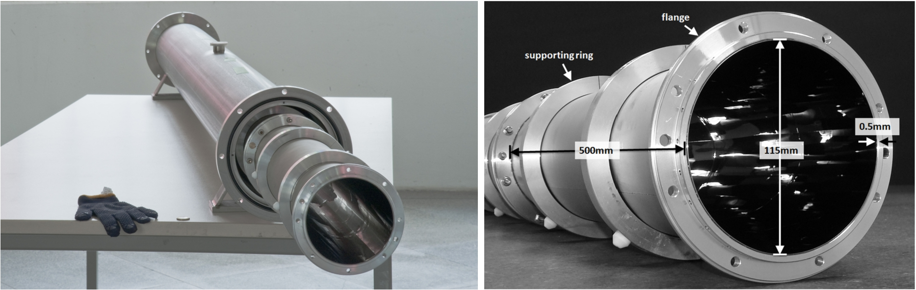
Replica foils for the FRM II are produced by the company S-DH (Sputter-Dünnschichttechnik Heidelberg). They have a maximal surface area of . To obtain guides, the foils have to be rolled and then welded along the longitudinal seam. Not to damage the inner surface, it is important not to weld through the natural-nickel supporting layer. If the UCN reflecting layer is touched, this can lead to uncertain effects on the inner surface, where neutrons can be lost. Currently the S-DH company is able to produce guide elements out of several pieces which are welded together to a maximum length of , which can be connected via flanges to longer guide sections. Figure 5 shows a complete replica guide with supporting rings, flanges and its cladding tube. The inner diameter of the replica tube is , the outer diameter is 116 mm. The inner diameter of the cladding tube is .
Left: a part of a replica foil with its supporting aluminium ring and its flange at the end of the foil is shown. Right: photograph of two connected replica foils with their dimensions.
These guides were experimentally characterized [2,8,20,29]. Thereby the transmission and storage properties have been investigated. The transmission per unit of guide length was measured to be for UCN in the energy range of , and by a UCN storage experiment the loss probability per wall bounce was determinded to be in the range of . This means that even after of UCN transport more then 50% of the initial neutron flux can reach a connected experiment.
Current status of the FRM II UCN source
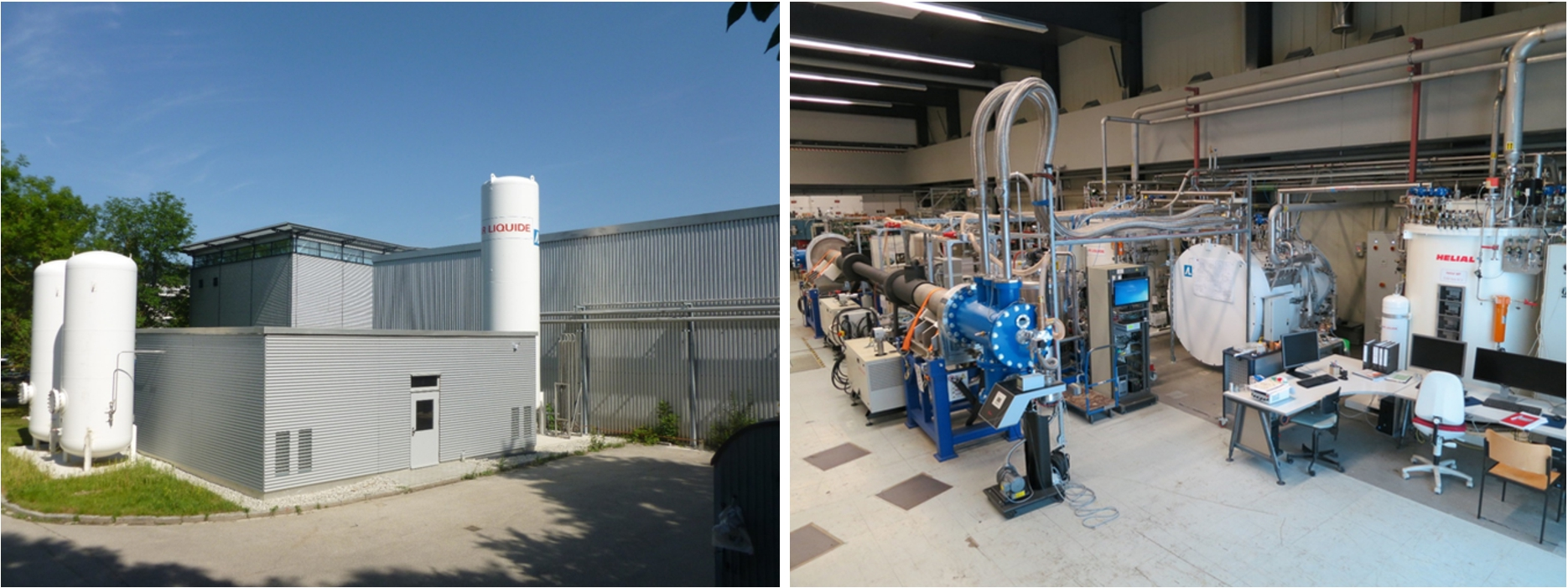
The nuclear licensing procedures of the FRM II UCN source require a complete non-nuclear test of all components before their installation and commissioning at the FRM II. Such a test setup of all important components of the UCN source has been installed at the Maier-Leibnitz-Laboratory (MLL), see Fig. 6.
Three vessels, one filled with liquid nitrogen () and two filled with gaseous helium ( each, ), have been set up outside south of the MLL building. A wide and high hall, made out of wood, houses the two compressors (electrical power each, , helium mass flow ) of each cold box, accompanied by two oil separators and water filled circuits for the cooling of the compressors. A small cooling tower next to the compressor hall removes the produced heat from the water cooling circuits. The helium cooling machines themselves are located inside the MLL. Two conventional cooling machines with a power of at each remove the heat from a closed cooling cycle of supercritical helium. In each machine the compressed helium gas is precooled by liquid nitrogen to , and then further cooled down by two Brayton cycles driven by turbines to . Below this temperature two Joule-Thomson expansion valves produce liquid helium (liquefaction rate each) and deliver it to a third cold box. The liquid helium is then used to cool a closed loop of supercritical helium (, helium mass flow ) via two heat exchangers. This closed loop, which is driven by a special pump, is connected with cryogenic transfer lines to the converter vessel inside of the SR6 beam tube, housing the solid deuterium and the solid hydrogen.
A rebuild of the beam tube SR6, where all the converter parts of the UCN source are located, has been set up. For non-nuclear tests the heat input of the FRM II to the converter is simulated by several heating devices. With all these systems in place, the UCN source has started its non-nuclear test phase. In these tests all parameters influencing the operation of the cooling machines and all necessary auxiliary systems will be varied to optimize the procedure to freeze out deuterium and hydrogen, with the simulated nuclear heat load of the FRM II. After the tests the whole cooling machine, together with the helium and liquid nitrogen vessels, will be transferred to the FRM II, and all the other parts of the source and auxiliary systems will be built and installed.
Left: at the south side of the MLL building a wide and high housing for two helium compressors and their oil removal system has been build. The two vessels on the left are filled with gaseous helium, the vessel on the right contains liquid nitrogen. Right: two conventional cooling machines (right hand side of the picture) produce liquid helium, which is supplied to a third cold box to remove the heat from a closed cooling loop with supercritical helium. A rebuild of the beam tube SR6 (left hand side of the picture), together with all inpile parts of the UCN source, has been set up.
Possible impacts for a UCN source at the ESS
At the ESS the development and installation of VCN and UCN sources is planned within the HighNESS project. There are two principle options for a UCN source, an inpile source or a beam source, hereby meaning that an inpile location is inside the ESS monolith () [21,22], and that a beam source can be placed either outside of the monolith but inside the bunker or outside of the bunker (). For inpile UCN sources four possible locations inside the monolith and two different converter materials – solid and superfluid He (He-II) – have been identified. The main challenges in all positions are the cooling of a source, the extraction of the UCN to connected experiments and the placement of all necessary equipment for cooling and extraction.
At all inpile positions the heat input to the converter material and the supporting structures will be significant. Without knowing an exact position or geometry of a future UCN source, a comparison between the FRM II liquid cold source and the ESS lower liquid moderator, which will possibly deliver cold neutrons to a future UCN source, can give an estimation of the necessary cooling power. At the FRM II the heat load on the cold source is ( of liquid at ), which is removed by a cooling system delivering of helium gas at a temperature of [44]. At the ESS the expected heat load on the lower cold source is ( of liquid ), which shall be removed by a mass flow of helium gas of at a temperature of [9]. Comparing this and the neutron fluxes at FRM II and ESS one can expect that the heat load on a UCN source at ESS will be approximately one order of magnitude higher than on the UCN source at FRM II if the source is placed at a similar position. This means that at the ESS for a UCN source a heat load of at least several kW at can be expected, taking into account that the heat load on the FRM II UCN source is . A cooling power of several kW at is technically feasible, but already requires cooling machines at the commercially available upper power limit. Concerning the fact, that for a He-II source temperatures below are desired, thus requiring even more high-power cooling techniques, a source for the inpile case seems to be more realistic and easier achievable, although Serebrov et al. have demonstrated at the WWR-M reactor at PNPI that, with an efficient thermal shielding and powerful cooling techniques, it is possible to remove of heat from a He-II converter at a temperature of [55]. An effective converter thickness of a few cm would be sufficient, if the UCN source is placed at a position where a strong cold neutron flux from the lower liquid moderator hits the deuterium converter. Also a real thin film source as described in ref. [70] could be installed at an inpile position, if a large effective converter area is available.
Considering the case of as converter material for a future UCN source at ESS, the freeze-out procedures tested at the FRM II could be used to produce transparent crystals. Freeze-out is possible via resublimation under conditions as described in Section 3.2, or from the liquid phase. In the latter case, direct horizontal extraction of the UCN is only possible through a window, or by vertical extraction upwards followed by a reflection to a horizontal direction. In any case one can expect a certain decrease of the transparency of the crystal and the formation of frost on the surface of the , as described in ref. [5]. From time to time hence a thermal cycling (“conditioning”) of the crystal could be necessary to increase its transparency and remove the frost from the surface, which should be foreseen when designing the cooling facility of the UCN source.
Due to the strong irradiation of a converter to be expected at most suitable inpile positions, the population will be larger than 99% if the temperature is below , as described in Section 3.3. Although the state will be fully populated after a few hours of irradiation, an initial para-to-ortho conversion of the deuterium will most probably be necessary. The thermal conductivity of ortho-deuterium at is approximately one order of magnitude higher than of deuterium with the natural para-ortho-mixture [26,27], which would strongly decrease the heat removal from the crystal. If one considers a UCN source with a small amount of deuterium as at the FRM II source, only a small and compact para-to-ortho conversion device as described in Section 3.1 would be necessary. One has to mention that meanwhile the catalyst OXISORB® is no longer produced, but most probably also other materials with a strong magnetic moment are suitable for catalytic para-to-ortho conversion, a field which is subject of current and future research.
At any inpile position the efficient transport of UCN from the source to an experiment is important, as in this case a distance of several tens of meters has to be passed. The newest generation of replica guides, as described in Section 4, are a valuable option for this purpose. With a transmission probability of such distances can be passed with losses of less than 50%. Furthermore, these replica guides are radiation resistant, which is of particular importance at inpile positions of a UCN source at the ESS. Also adapted diameters of replica guides are possible, as these are fabricated by welding of foils of variable size.
In summary, a small UCN source – similar as planned at the FRM II – seams a feasible option if the converter shall be placed at an inpile position close to the lower moderator. The latter already delivers neutrons in a suitable energy range, so that no further premoderation with hydrogen or deuterium is necessary. The necessary small amount of can be cooled with commercially available helium refrigerators or liquefiers. The results of research performed during the last years at the FRM II on converter preparation, para-to-ortho conversion, radiation effects and UCN transport, can at least partially be transferred and used as input for the design and construction of a future UCN source at ESS.
Footnotes
Acknowledgements
The author thankfully acknowledges the support of innumerable scientists, engineers, technicians and students from the Physics Department E18 of TUM, the Maier-Leibnitz-Laboratory of TUM and LMU, the TRIGA Mainz, the ILL, the University of Applied Sciences Augsburg, the FRM II and the MLZ.
References
1.
AbelC.et al., Measurement of the permanent electric dipole moment of the neutron, Phys. Rev. Lett.124 (2020), 081803. doi:10.1103/PhysRevLett.124.081803.
2.
AltarevI.DaumM.FrankeB.FreiA.GeltenbortP.GutsmiedlE.HartmannF.J.MaterneS.MüllerA.R.PickerR.SchreckenbachK. and StoeplerR., ILL experimental report 3-14-250, 2008.
3.
AltarevI.FreiA.GeltenbortP.GutsmiedlE.HartmannF.J.MüllerA.R.PaulS.PlonkaC. and TortorellaD., A method for evaluating the transmission properties of ultracold-neutron guides, Nucl. Instrum. and Meth. A570 (2007), 101. doi:10.1016/j.nima.2006.09.104.
AnghelA.et al., Solid deuterium surface degradation at ultracold neutron sources, Eur. Phys. J. A54 (2018), 148. doi:10.1140/epja/i2018-12594-2.
6.
ArzumanovS.BondarenkoL.ChernyavskyS.GeltenbortP.MorozovV.NesvizhevskyV.V.PaninY. and StrepetovA., A measurement of the neutron lifetime using the method of storage of ultracold neutrons and detection of inelastically up-scattered neutrons, Phys. Lett. B745 (2015), 79. doi:10.1016/j.physletb.2015.04.021.
7.
AtchisonF.et al., Ortho-para equilibrium in a liquid neutron moderator under irradiation, Phys. Rev. B68 (2003), 094114. doi:10.1103/PhysRevB.68.094114.
8.
BeckL.DeuschleT.FreiA.GeltenbortP.HuberT.SchreckenbachK.StoeplerR. and WlokkaS., Ill experimental report 3-14-287, 2010.
9.
BeßlerY., Moderator cooling at ESS, HighNESS / LENS workshop on Very Cold and Ultra Cold Sources for ESS, 2022.
10.
BisonG.et al., Comparison of ultracold neutron sources for fundamental physics measurements, Phys. Rev. C95 (2017), 045503. doi:10.1103/PhysRevC.95.045503.
11.
BlauB.DaumM.FertlM.GeltenbortP.GöltlL.HenneckR.KirchK.KnechtA.LaussB.Schmidt-WellenburgP. and ZsigmondG., A prestorage method to measure neutron transmission of ultracold neutron guides, Nucl. Instrum. and Meth. A807 (2016), 30. doi:10.1016/j.nima.2015.10.075.
12.
BodekK.et al., An apparatus for the investigation of solid with respect to ultra-cold neutron sources, Nucl. Instrum. Methods Phys. Res. A533 (2004), 491. doi:10.1016/S0168-9002(04)01562-1.
13.
CollinsG.W.FearonE.M.MapolesE.R.TsugawaR.T.SouersP.C. and FeddersP.A., to conversion in solid D–T, Phys. Rev. B44 (1991), 6598. doi:10.1103/PhysRevB.44.6598.
14.
DaumM.et al., Transmission of ultra-cold neutrons through guides coated with materials of high optical potential, Nucl. Instrum. and Meth. A741 (2014), 71. doi:10.1016/j.nima.2013.12.050.
15.
DaumM.FreiA.GeltenbortP.GutsmiedlE.HöbelP.KochH.-C.KraftA.LauerT.MüllerA.R.PaulS. and ZsigmondG., A low-pass velocity filter for ultracold neutrons, Nucl. Instrum. and Meth. A675 (2012), 103. doi:10.1016/j.nima.2012.02.007.
16.
EzhovV.F.et al., Measurement of the neutron lifetime with ultracold neutrons stored in a magneto-gravitational trap, JETP Lett.107 (2018), 671. doi:10.1134/S0021364018110024.
17.
FreiA., Produktion von ultrakalten Neutronen mit einem festen Deuteriumkonverter, Ph.D. Dissertation, Technical University of Munich, 2008.
18.
FreiA.et al., First production of ultracold neutrons with a solid deuterium source at the pulsed reactor TRIGA Mainz, Eur. Phys. J. A34 (2007), 119. doi:10.1140/epja/i2007-10494-2.
19.
FreiA.GutsmiedlE.MorkelC.MüllerA.R.PaulS.RolsS.SchoberH. and UnruhT., Understanding of ultra-cold-neutron production in solid deuterium, Europhysics Letters92 (2010), 62001. doi:10.1209/0295-5075/92/62001.
20.
FreiA.SchreckenbachK.FrankeB.HartmannF.J.HuberT.PickerR.PaulS. and GeltenbortP., Transmission measurements of guides for ultra-cold neutrons using UCN capture activation analysis of vanadium, Nucl. Instrum. and Meth. A612 (2010), 349. doi:10.1016/j.nima.2009.10.101.
21.
GarobyR.et al., The European Spallation Source design, Phys. Scr.93 (2018), 014001. doi:10.1088/1402-4896/aa9bff.
22.
GarobyR.et al., Corrigendum: The European Spallation Source design (2018 Phys. Scr. 93 014001), Phys. Scr.93 (2018), 129501. doi:10.1088/1402-4896/aaecea.
23.
GolubR. and PendleburyJ.M., Super-thermal sources of ultra-cold neutrons, Phys. Lett. A53 (1975), 133. doi:10.1016/0375-9601(75)90500-9.
24.
GolubR. and PendleburyJ.M., The interaction of Ultra-Cold Neutrons (UCN) with liquid helium and a superthermal UCN source, Phys. Lett. A62 (1977), 337. doi:10.1016/0375-9601(77)90434-0.
HuberT., Transport and storage of ultra-cold neutrons in replika-guides, Diploma thesis, Technical University of Munich, 2011.
30.
ItoT.M.et al., Performance of the upgraded ultracold neutron source at Los Alamos National Laboratory and its implication for a possible neutron electric dipole moment experiment, Phys. Rev. C97 (2018), 012501. doi:10.1103/PhysRevC.97.012501.
31.
KarchJ.SobolevY.BeckM.EberhardtK.HampelG.HeilW.KieserR.ReichT.TrautmannN. and ZiegnerM., Performance of the solid deuterium ultra-cold neutron source at the pulsed reactor TRIGA Mainz, Eur. Phys. J. A50 (2014), 78. doi:10.1140/epja/i2014-14078-9.
32.
KorobkinaE.WehringB.W.HawariA.I.YoungA.R.HuffmanP.R.GolubR.XuY. and PalmquistG., An ultracold neutron source at the NC State University PULSTAR reactor, Nucl. Instrum. and Meth. A579 (2007), 530. doi:10.1016/j.nima.2007.04.116.
33.
KüglerK.J.PaulW. and TrinksU., Properties of straight and curved neutron guide tubes, Z. Phys. B39 (1980), 361. doi:10.1007/BF01305837.
34.
LauerT. and ZechlauT., A prospective pulsed source of ultracold neutrons for experiments in fundamental neutron physics, Eur. Phys. J. A49 (2013), 104. doi:10.1140/epja/i2013-13104-x.
35.
LaussB. and BlauB., UCN, the ultracold neutron source – neutrons for particle physics, SciPost Phys. Proc.5 (2021), 004. doi:10.21468/SciPostPhysProc.5.004.
36.
LiuC.-Y.YoungA.R. and LamoreauxS.K., Ultracold neutron upscattering rates in a molecular deuterium crystal, Phys. Rev. B62 (2000), R3581. doi:10.1103/PhysRevB.62.R3581.
37.
LushchikovV.I.PokotilovskiiY.N.StrelkovA.V. and ShapiroF.L., JETP Lett.9 (1969), 23.
38.
MartinJ.FrankeB.HatanakaK.KawasakiS. and PickerR., The TRIUMF UltraCold advanced neutron source, Nuclear Physics News31 (2021), 19. doi:10.1080/10619127.2021.1881367.
39.
MasudaY.HatanakaK.JeongS.-C.KawasakiS.MatsumiyaR.MatsutaK.MiharaM. and WatanabeY., Spallation ultracold neutron source of superfluid helium below 1 K, Phys. Rev. Lett.108 (2012), 134801. doi:10.1103/PhysRevLett.108.134801.
40.
MaysenhölderW., Effect of a sharp bend on the transmission of neutron guide tubes of circular cross section, Nucl. Instrum. Meth.137 (1976), 291. doi:10.1016/0029-554X(76)90340-2.
41.
MüllerA.R., Characterization of solid as source material for ultra cold neutrons and development of a detector concept for the detection of protons from the neutron decay, Ph.D. Dissertation, Technical University of Munich, 2008.
42.
NesvizhevskyV.V., Polished sapphire for ultracold-neutron guides, Nucl. Instrum. and Meth. A557 (2006), 576. doi:10.1016/j.nima.2005.10.024.
43.
NesvizhevskyV.V.et al., Comparison of specularly reflecting mirrors for GRANIT, Nucl. Instrum. and Meth. A578 (2007), 435. doi:10.1016/j.nima.2007.05.319.
44.
PätheD., Kalte Quelle mit Hilfseinrichtungen JBB10, QKQ20, JBB30, JBB40, QVQ50, QVQ60/6S, QKE80, CPQ, Forschungs-Neutronenquelle Heinz Maier-Leibnitz (FRM II), 2015.
45.
PattieR.W.Jr.et al., Measurement of the neutron lifetime using a magneto-gravitational trap and in situ detection, Science360 (2018), 627. doi:10.1126/science.aan8895.
46.
PendleburyJ.M.et al., Revised experimental upper limit on the electric dipole moment of the neutron, Phys. Rev. D92 (2015), 092003. doi:10.1103/PhysRevD.92.092003.
47.
PichlmaierA.VarlamovV.SchreckenbachK. and GeltenbortP., Neutron lifetime measurement with the UCN trap-in-trap MAMBO II, Phys. Lett. B693 (2010), 221. doi:10.1016/j.physletb.2010.08.032.
48.
PiegsaF.M.FertlM.IvanovS.N.KreuzM.LeungK.K.H.Schmidt-WellenburgP.SoldnerT. and ZimmerO., New source for ultracold neutrons at the institut Laue-Langevin, Phys. Rev. C90 (2014), 015501. doi:10.1103/PhysRevC.90.015501.
49.
PlonkaC.GeltenbortP.SoldnerT. and HäseH., Replika mirrors – nearly loss-free guides for ultracold neutrons – measurement technique and first preliminary results, Nucl. Instrum. and Meth. A578 (2007), 450. doi:10.1016/j.nima.2007.05.314.
50.
SaterJ.D.GainesJ.R.FearonE.M.SouersP.C.McMurphyF.E. and MapolesE.R., Ortho-to-para conversion in solid tritium. II. Experimental values, Phys. Rev. B37 (1988), 1482. doi:10.1103/PhysRevB.37.1482.
SerebrovA.et al., Measurement of the neutron lifetime using a gravitational trap and a low-temperature Fomblin coating, Phys. Lett. B605 (2005), 72. doi:10.1016/j.physletb.2004.11.013.
53.
SerebrovA.P.et al., Ultracold-neutron infrastructure for the PNPI/ILL neutron EDM experiment, Nucl. Instrum. and Meth. A611 (2009), 263. doi:10.1016/j.nima.2009.07.084.
54.
SerebrovA.P.et al., New search for the neutron electric dipole moment with ultracold neutrons at ILL, Phys. Rev. C92 (2015), 055501. doi:10.1103/PhysRevC.92.055501.
55.
SerebrovA.P.et al., J. Phys.: Conf. Ser.798 (2017), 012147.
56.
SerebrovA.P.et al., Neutron lifetime measurements with a large gravitational trap for ultracold neutrons, Phys. Rev. C97 (2018), 055503. doi:10.1103/PhysRevC.97.055503.
57.
SerebrovA.P.FominA.K.OneginM.S.KharitonovA.G.PrudnikovD.V.LyamkinV.A. and IvanovS.A., The project of ultracold neutron sources at the PIK reactor with superfluid helium as a moderator, Tech. Phys. Lett.40 (2014), 10. doi:10.1134/S1063785014010118.
58.
SerebrovA.P.MityukhlyaevV.A.ZakharovA.A.NesvizhevskyV.V. and KharitonovA.G., JETP Lett.59 (1994), 757.
59.
ShevtsovV.FrolovA.LukashevichI.YlinenE.MalmiP. and PunkkinenM., The ortho-to-para conversion in solid hydrogen, catalyzed by hydrogen atoms, J. Low Temp. Phys.95 (1994), 815. doi:10.1007/BF00754716.
60.
SilveraI.F., The solid molecular hydrogens in the condensed phase: Fundamentals and static properties, Rev. Mod. Phys.52 (1980), 393. doi:10.1103/RevModPhys.52.393.
61.
SobolevY.et al., Cubic boron nitride: A new prospective material for ultracold neutron application, Nucl. Instrum. and Meth. A614 (2010), 461. doi:10.1016/j.nima.2009.12.035.
62.
SouersP.C., Hydrogen Properties for Fusion Energy, University of California Press, 1986.
63.
SteyerlA., Measurements of total cross sections for very slow neutrons with velocities from 100 m/sec to 5 m/sec, Phys. Lett. B29 (1969), 33. doi:10.1016/0370-2693(69)90127-0.
64.
SteyerlA., Effect of surface roughness on the total reflexion and transmission of slow neutrons, Z. Phys. A254 (1972), 169. doi:10.1007/BF01380066.
65.
SteyerlA.NagelH.SchreiberF.X.SteinhauserK.A.GählerR.GläserW.AgeronP.AstrucJ.M.DrexelW.GervaisG. and MampeW., A new source of cold and ultracold neutrons, Phys. Lett. A116 (1986), 347. doi:10.1016/0375-9601(86)90587-6.
66.
UtsuroM. and OkumuraK., Production and guide tube transmission of very cold neutrons from pulsed cold source, J. Nucl. Sci. Technol.19 (1982), 863. doi:10.1080/18811248.1982.9734232.
67.
WeitzelD.H.LoebensteinW.V.DraperJ.W. and ParkO.E., Ortho-para catalysis in liquid-hydrogen production, J. Res. Natl. Bur. Stand.60 (1958), 221. doi:10.6028/jres.060.026.
68.
WlokkaS., Kryo-Konvertermaterialien zur Erzeugung ultrakalter Neutronen und Untersuchungen an Testaufbauten der neuen UCN-Quelle am FRM II, Diploma thesis, Technical University of Munich, 2011.
69.
WlokkaS., Aspects of ultra-cold neutron production in radiation fields at the FRM II, Ph.D. Dissertation, Technical University of Munich, 2016.
70.
YuZ.-C.MalikS.S. and GolubR., A thin film source of ultra-cold neutrons, Z. Phys. B62 (1986), 137. doi:10.1007/BF01323423.
71.
ZechlauT., Ultra-cold neutron transport and spin manipulation system for the measurement of the neutron electric dipole moment, Ph.D. Dissertation, Technical University of Munich, 2016.
72.
ZimmerO.BaumannK.FertlM.FrankeB.MironovS.PlonkaC.RichD.Schmidt-WellenburgP.WirthH.-F. and van den BrandtB., Superfluid-helium converter for accumulation and extraction of ultracold neutrons, Phys. Rev. Lett.99 (2007), 104801. doi:10.1103/PhysRevLett.99.104801.
73.
ZimmerO.PiegsaF.M. and IvanovS.N., Superthermal source of ultracold neutrons for fundamental physics experiments, Phys. Rev. Lett.107 (2011), 134801. doi:10.1103/PhysRevLett.107.134801.