
Abstract
The Challenge to stabilize the grid frequency increases with the increment of renewable energy resources. System inertia/frequency control is a significant concern for maintaining system stability with a fast response time during the load transition. This manuscript proposes surface-mounted permanent magnet synchronous generator (SPMSG) based wind energy conversion system (WECS) with a frequency support DC-link controlling loop and a converter protective DC-link voltage-controller frequency support system. To achieve power exchange, the frequency control system (FCS) for the SPMSG-based wind turbine supports the grid-side virtual inertia. The DC-link voltage is disturbed during the load transition to maintain the frequency, while the electrolytic capacitor requires extra care regarding the DC bus voltage. This manuscript incorporates the FCS system with a supercapacitor and dynamic voltage limiter to avoid additional care of the DC bus voltage. A detailed analysis of system frequency with the additional load increment, normal connected load decrement, and various fault scenarios has been done. The proposed system is compared with the existing virtual inertia support (VIS). The simulation results show that the proposed frequency control system-based VIS efficiently limits the frequency deviations & DC-link voltage. The results are verified in the OPAL-RT 4510 real-time simulator environment to ensure the efficacy of the proposed system.
Keywords
Introduction
Renewable energy sources (RESs) are typically connected to the external grid via converters. Their penetration increases, causing the whole system’s inertia to decrease, creating problems during frequency control & power outages [1, 2]. In the event of a sudden power loss or an increase in energy requirement, synchronous generators have been able to release kinetic energy from their rotating mass to reduce the frequency change rate instantly. In contrast, variable speed turbine systems (VSWTs) connected to the ac power grid via voltage source converters (VSCs) are naturally considered inertia-less compared to ac power systems [3–5]. Because of the low inertia, variations in generation or load may cause a significant deviation in frequency, potentially leading to system instability. Multiple control methods, including frequency & voltage control, have been used to maintain the stability of electricity grids [6, 7]. The two techniques most frequently employed in WECS for rapid frequency control are rotor VIS and DC-link VIS. The rotor VIS has issues like high-frequency measurement noise, and also affects the Maximum power point tracking (MPPT) control, whereas DC-link VIS can avoid these issues. But Conventional capacity DC capacitors have a limited amount of usable electrostatic energy [8, 9]. Supercapacitors are added in the WECS for frequency support to alleviate this problem.Batteries, flywheels, and magnetic storage, other energy storage devices can be employed to provide inertial support for frequency regulation [10–12]. However, for VIS, the supercapacitor is more economically viable. Energy and power density are essential considerations in determining energy storage technology applications [13, 14]. Batteries and flywheels have much energy density but low power densities; supercapacitors have high power but low-energy density, which is vital to inertia control. Inertial control needs rapidly changing power sources. The energy density of a supercapacitor is usually a hundred times larger than that of conventional capacitors, and the power density is ten times greater than batteries [15]. To reduce the impact of wind variation a supercapacitor is directly connected between the machine-side converter (MSC) and gird-side converter (GSC). Various DC voltage levels are permitted to optimize the use of storage capacity.
On the other hand, the GSC control system is not intended to mimic the power behavior of machine inertia. As a result, supercapacitors are seen to be the best option. Cost and controlling the complexity of storage devices are often a source of concern for system operators [16, 17]. So, frequency control with a DC bus control interface between the utility grid and RES through back-to-back converters offers a cost-effective solution [18].
The additional control is applied in wind turbine generators to release the stored energy from the back-to-back converter capacitor to smooth the voltage. This additional loop involves inertia/frequency support [19–22]. In [23, 24], the authors utilize the virtual inertia-based frequency-sensitive system to eliminate new/additional converter inverter costs. The total energy contribution from kinetic energy-based inertial control is determined by the inertial control gain and the system frequency response [25]. In [26], the authors analyzed the effect of the gain of inertial control on the system frequency response of WECS. In [27–30], the authors estimated the gain of inertial control and DC-link capacitor based control has been estimated by the authors using various kinds of approximation strategies. According to [30] active power control is affected by inertial gain levels that are higher and lower. Additionally, there are problems with the dc-link capacitor gain’s higher and lower values. When the gain value is low, there is a problem with frequency control, and when the gain value is large, the threshold limit may be crossed [30–32]. In [32] author taken fixed value both inertial gain but it is not gives satisfactory performance.
Various methods have been developed in the context of frequency control (virtual inertia support). Energy density & power density are the factors that support the virtual inertia concept. The supercapacitor has low energy density but high power density. This paper compares existing and proposed control solutions for virtual inertia support in SPMSG. In the existing paper, the author analyses simultaneous control and cascading control to use the kinetic energy from wind turbine rotors and the DC-link capacitor energy to maintain inertia for the AC grid. The disadvantage of the first technique is that whenever frequency disturbances occur, MPPT point changes. Both inertia supports in cascading control will automatically activate in sequence [22]. It is cost-effective for low-frequency interruption events. That could not be an economical approach to large wind farms. In the existing system, fault analysis is not included. Conventional capacity DC capacitors have a limited amount of usable electrostatic energy. To resolve the above concerns the proposed FCS supercapacitor instead of the electrolytic capacitor has been used to avoid the extra system for DC voltage protection. The sensorless technique, synchronous reference frame-phase locked loop (SRF-PLL) is used to estimate rotor position for SPMSG-equipped wind turbine system. Sensorless rotor position estimation systems are more stable than sensor-based systems because it reduces disturbances in the DC-link voltage. The proposed frequency control system (FCS) can control the system in the case, load variations & fault conditions occur. The gain in FCS varies according to the behavior of frequency variation & DC-link voltage. The impact on the DC-link voltage through the FCS supercapacitor-equipped back-to-back converter system has been analysed.
The highlights of the proposed work are as follows: To estimate the rotor position for SPMSG-equipped wind turbine (WT), the sensorless technique (SRF-PLL) has been utilized. The frequency control during load transition with the modified IEEE-9 bus test system is proposed. A supercapacitor instead of the electrolytic capacitor has been proposed to avoid the extra system for DC voltage protection. The proposed system is simulated with load variations and fault disturbances scenarios. A comparison of existing and proposed control techniques has been made. Along with these, results are verified in the real-time simulator OPAL-RT 4510.
The structure of this manuscript is as follows: section 2 contains the proposed model of the frequency control system. Section 3, simulation & result analysis of the proposed model with different cases. At last, in section 4, the conclusion is presented.
Proposed model of frequency control system
The SPMSG wind energy conversion system (WECS) schematic diagram is shown in Fig. 1. Here the developed system senses the stator current and transforms it into the synchronous dq reference frame signal.
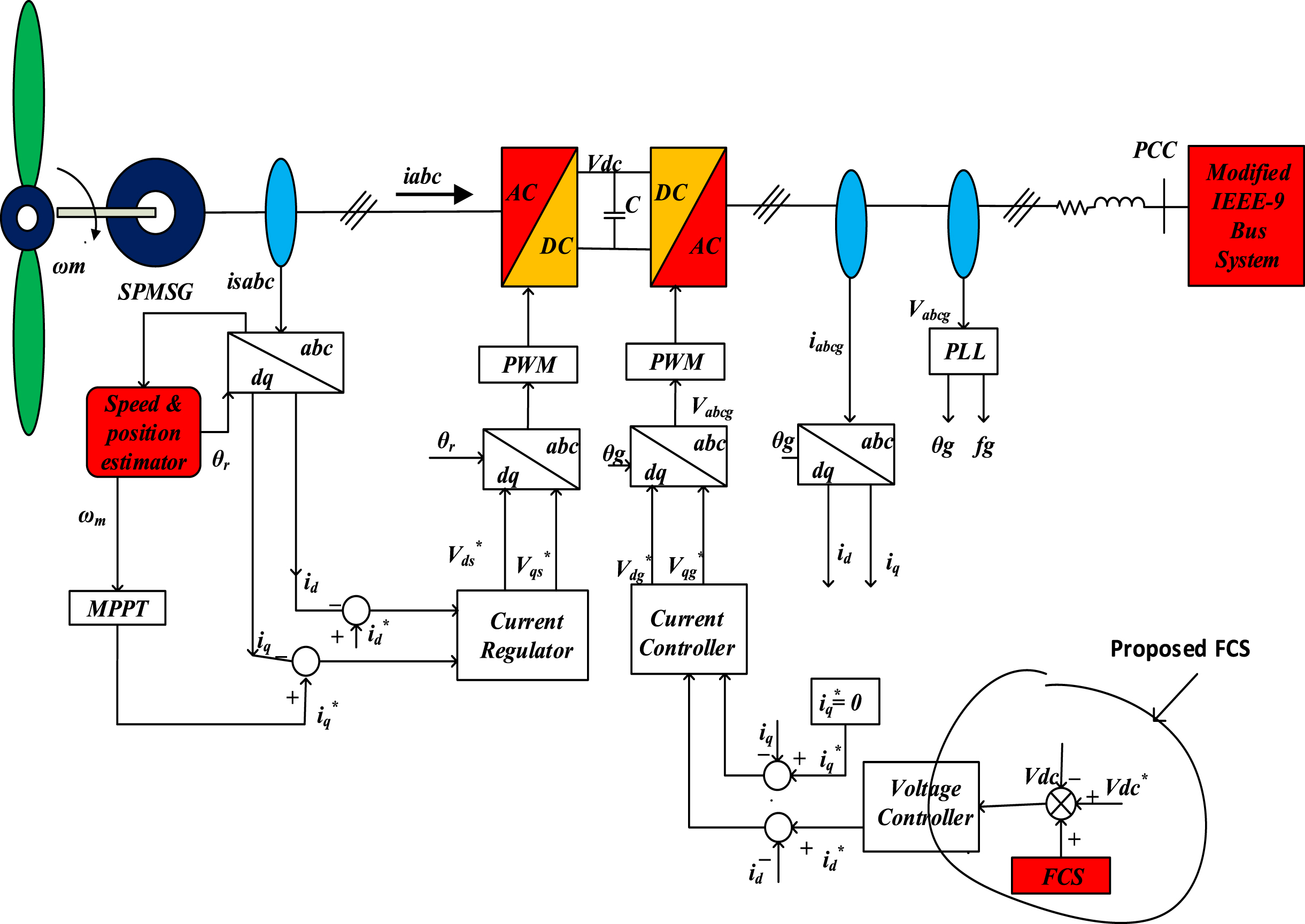
Schematic diagram of SPMSG WECS.
The converted rotating signal is fed to the speed & position estimator to estimate speed and position by using sensorless technique (SRF-PLL). The SRF-PLL block diagram is shown in Fig. 2. The sensorless technique takes less time to obtain the calculated speed to the sensor. The average error in speed and position estimation is less in the sensorless technique to the sensor. Due to the error minimization the power extraction from wind through MPPT control is good. The MPPT extracts stable power through sensorless techniques as compared to the sensor.
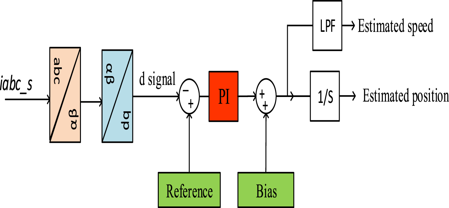
Block diagram of SRF-PLL.
The DC power delivered through the DC-link capacitor is equivalent to the converter’s active power. The DC bus voltage will be impacted if there is a change in the converter’s active power. The power exchange between machine to grid via DC-link capacitor the stability in power exchange improves the stability of the system through stable DC-link & it is achieved effectively with sensorless technique [32]. The modified IEEE-9 bus test system is connected to the point of common coupling (PCC) at the grid using the back-to-back converter.
The existing control technique for inertia support is shown in Fig. 3.
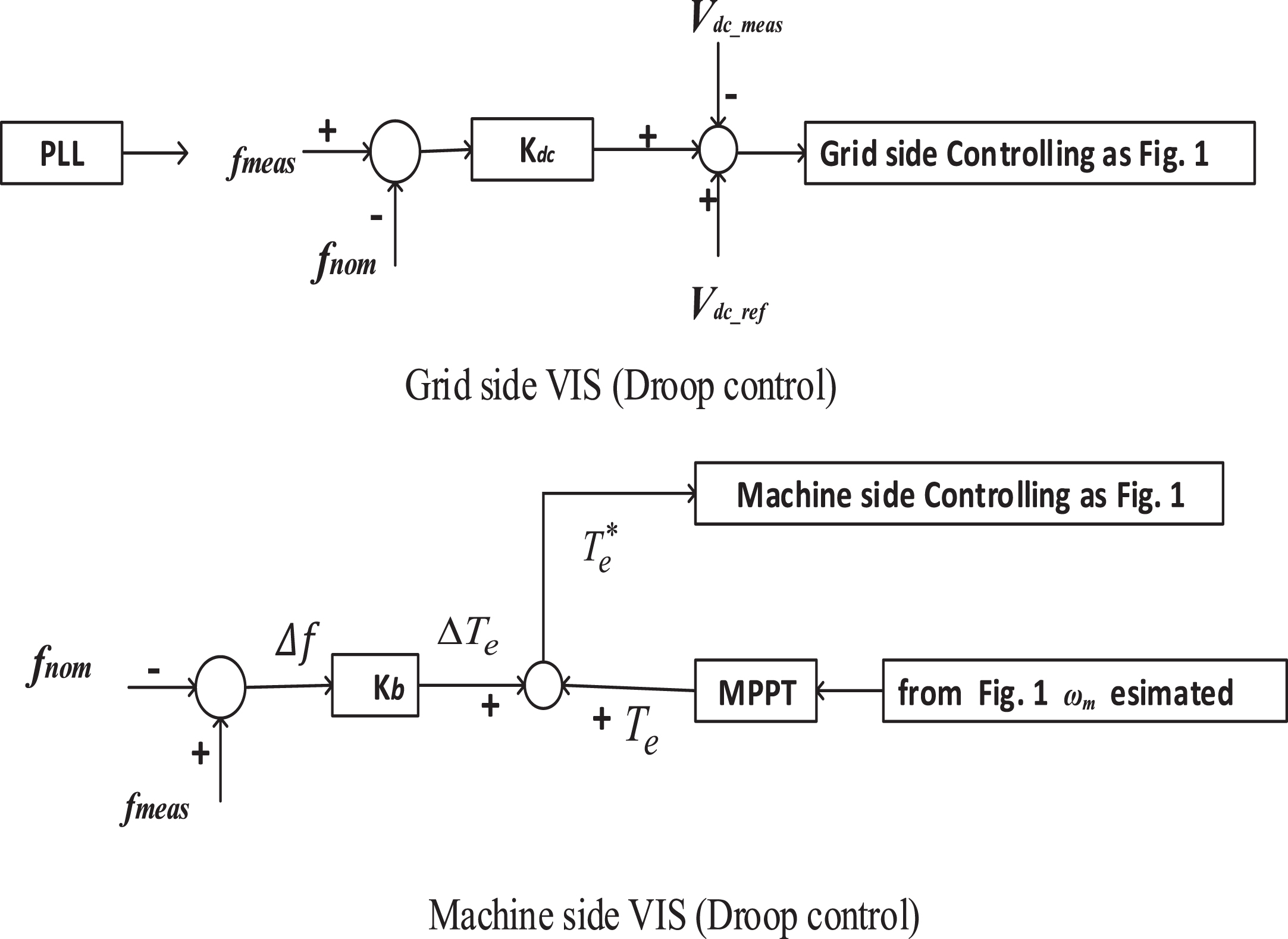
Existing control technique for inertia support [22].
The proposed frequency control system is implemented by the frequency control system gain K fcs in the dc-voltage controller loop. Figure 4 shows the proposed scheme.
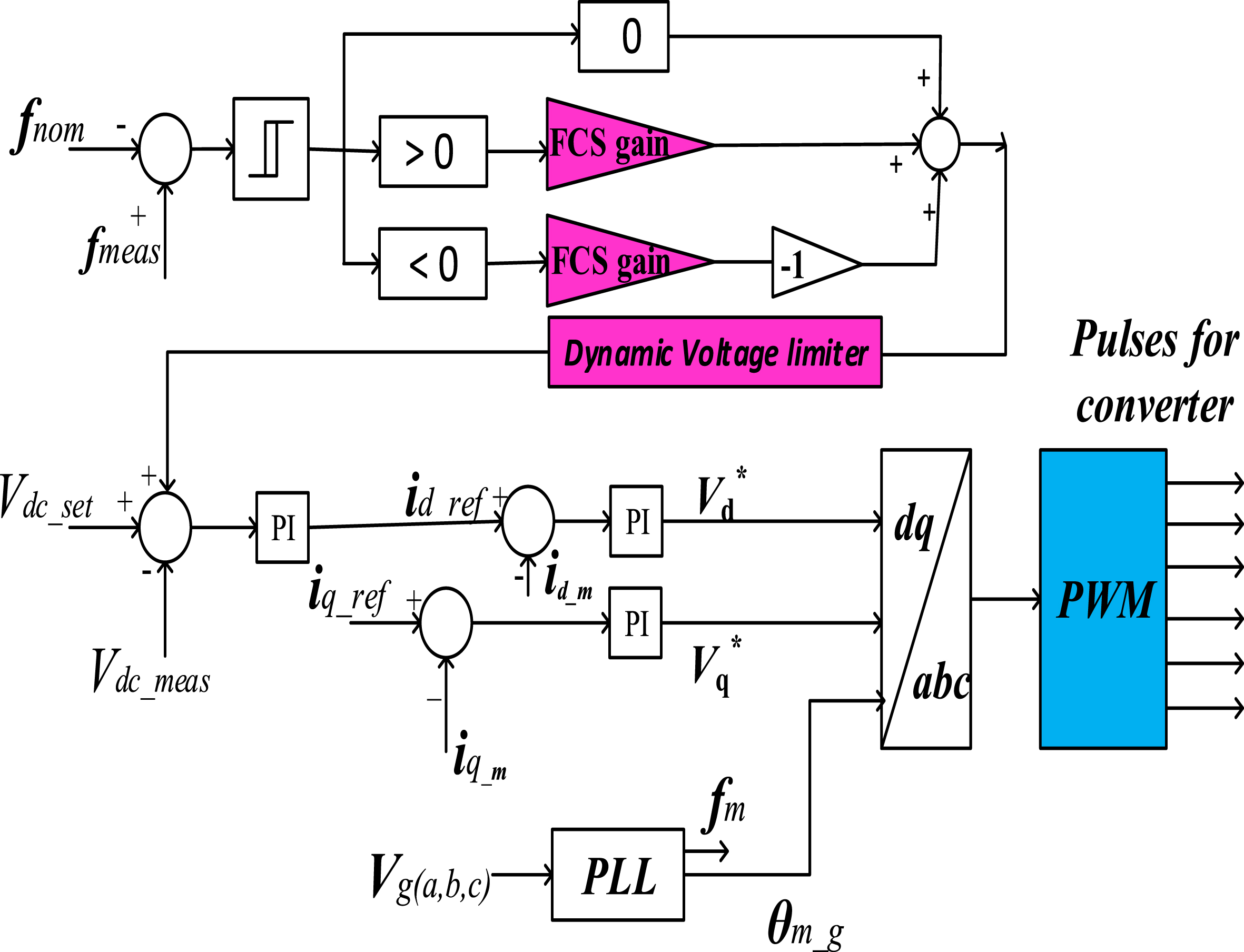
Schematic diagram of proposed FCS system.
The FCS depends on the control of DC-link voltage & reactive power control of the grid-side converter. The active power imbalance (absorption/release) depends on the value of supercapacitors and the virtual inertia constant (FCS gain) K
fcs
. The d-axis current is determined by the outer loop of the DC-voltage controller & taken as the reference current
It creates two regions to act
If Δf > 0, then
If Δf < 0, then
If Δf = 0, then not applicable for FCS gain
The FCS gain is dependent on the ratio of DC-link voltage (ΔV
dc
) and frequency deviation (Δf). The difference V
dc
is considered by using the maximum value of DC-link voltage
In this work, considering ΔV dc = 0.26pu and setting the frequency deviation of Δf = 0.006pu .
Now, FCS gain
The signal output from FCS is to be added to the DC-link voltage controller to maintain the disturbing signal to the referenced signal (
Here V
c
is the grid-side converter voltage (L-L). For getting the minimum DC voltage for the PWM modulation, the modulation index is taken as m = 1.1
For maximum DC-link voltage, the modulation index m = 0.7,
The minimum & maximum range of DC voltage is dynamic & it depends on V c equation (2). Here, dynamic DC bus voltage limits are implied by the controlling system.
The power supported by the supercapacitor (SC) as
ΔP= power exchange to grid through supercapacitor
Where P sc , i sc ,C sc are the power, current, and capacitance of the supercapacitor.
Supercapacitors’ high energy density makes them suitable for various power operations that require high instantaneous power for short intervals. The supercapacitors state of charge (SOC) may be expressed as follows:
SOC = current storage capacity of SC/ rated capacity of SC = current voltage of SC / (rated voltage of SC) 2
Despite having no rotating kinetic energy, the supercapacitor has a certain level of active power reserve. The supercapacitor can show an instant active power response with the proposed FCS control. As a result, the supercapacitor can be utilized as efficient energy storage to prevent abrupt frequency changes during sudden load increases and decreases, as well as different fault scenarios.
The modified IEEE-9 bus test system has been used in this manuscript to test the proposed system. Figure 5 shows the modified IEEE-9 bus load-connected system. Bus 1 has a 16.5 kV three-phase source with a PV generator of 151 MW, bus 2 has an 18 kV three-phase source with a PV generator of 163 MW, and bus 3 has a 1.5 MW 575 V SPMSG-based WECS system.
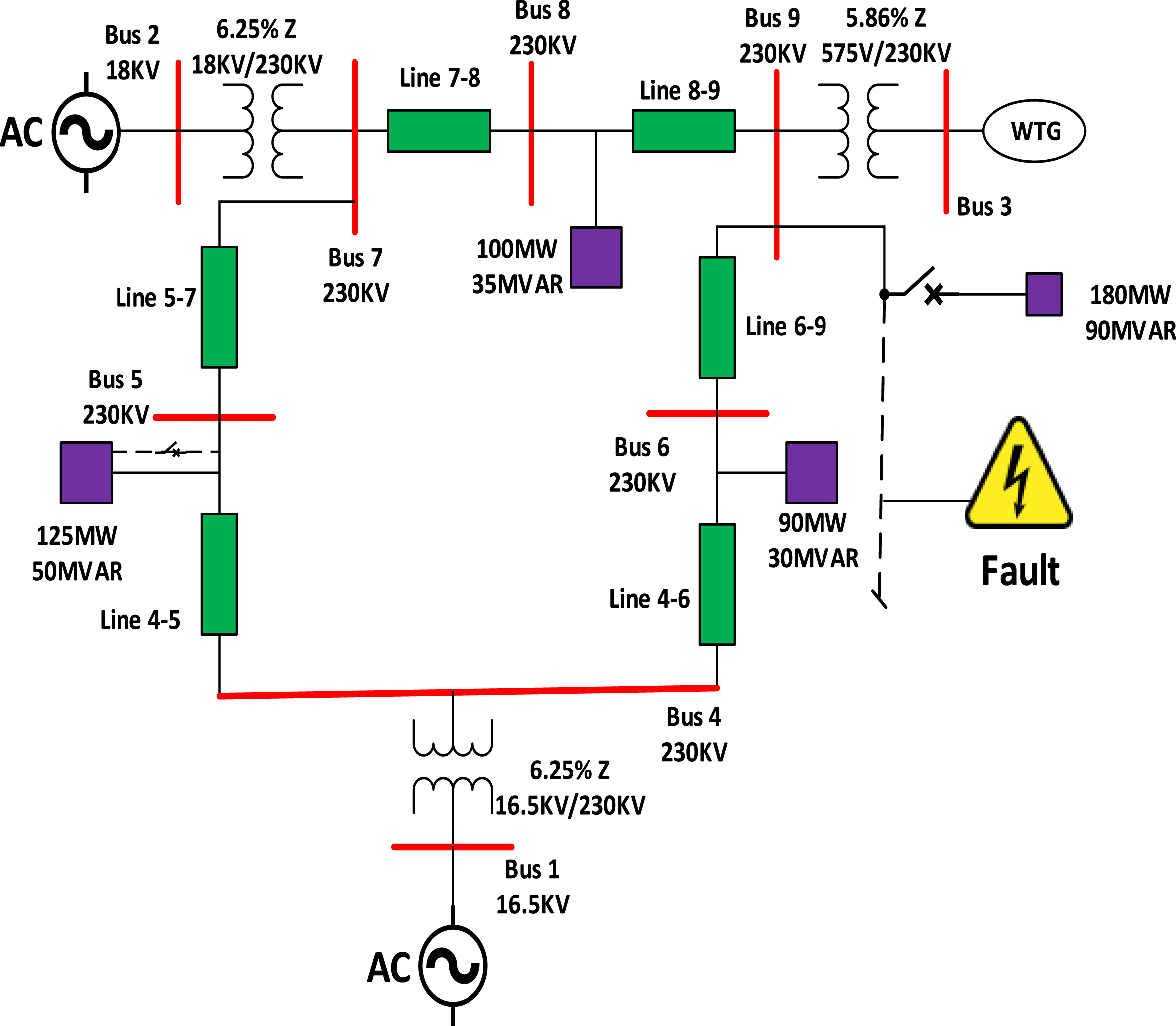
Modified IEEE-9 bus test system.
The loads are connected (modified IEEE-9 bus) as per Table 1 given below-
Load connection at modified IEEE-9 bus test system
The Increasing additional load during simulation for the system is at bus no. 9, and the load is P = 180 MW & Q = 60 Mvar in case 1. At a wind speed of 11 m/s, the simulation is performed. Figure 6 depicts wind speed (m/s).
This work verified that for the maximum frequency of 1.006pu and minimum frequency of 0.995pu, the deviation in frequency is±0.006pu with 60 Hz system frequency.
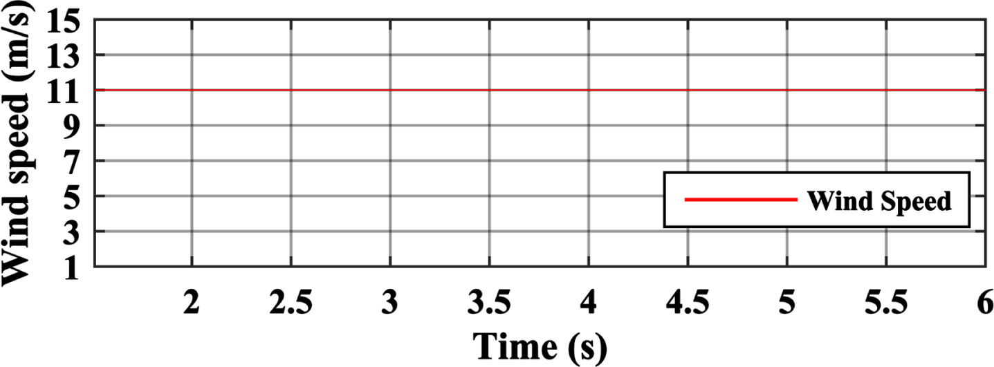
Wind speed.
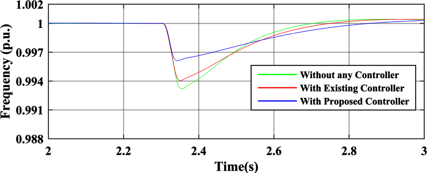
The nominal load of 315 MW and 105 Mvar is connected to the system. The load increment of P = 180 MW (57.1%) and Q = 60 Mvar increase at bus 9 on time t = 2.3 sec., and it indicates from Fig. 7 that the frequency control system (FCS) is working properly. The FCS-based system has a fast recovery of frequency dip, allowing a minor dip in frequency than without an FCS support system and compared with the existing system [22] of the proposed control strategies. From Fig. 7, it is clear that the frequency change Δf is 0.003pu with the proposed FCS system, while the existing system has produced the Δf is 0.005pu.
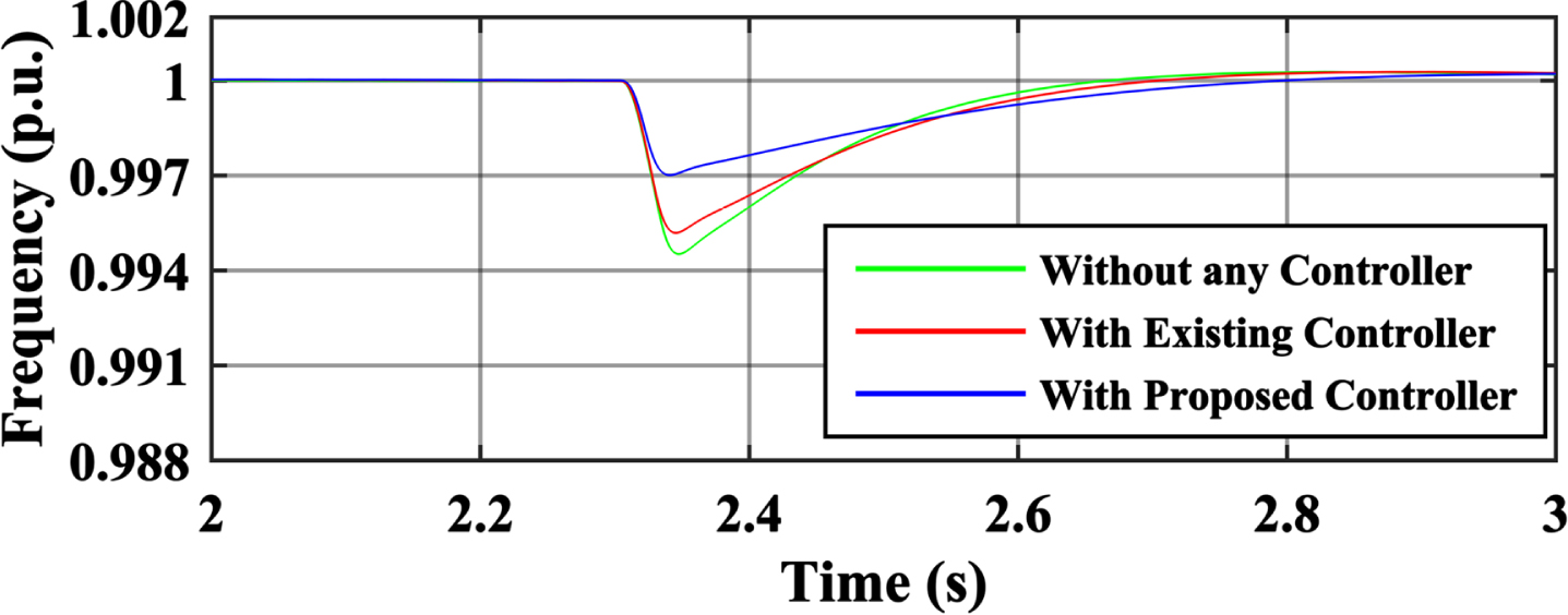
Frequency of the system in case of sudden load increment.
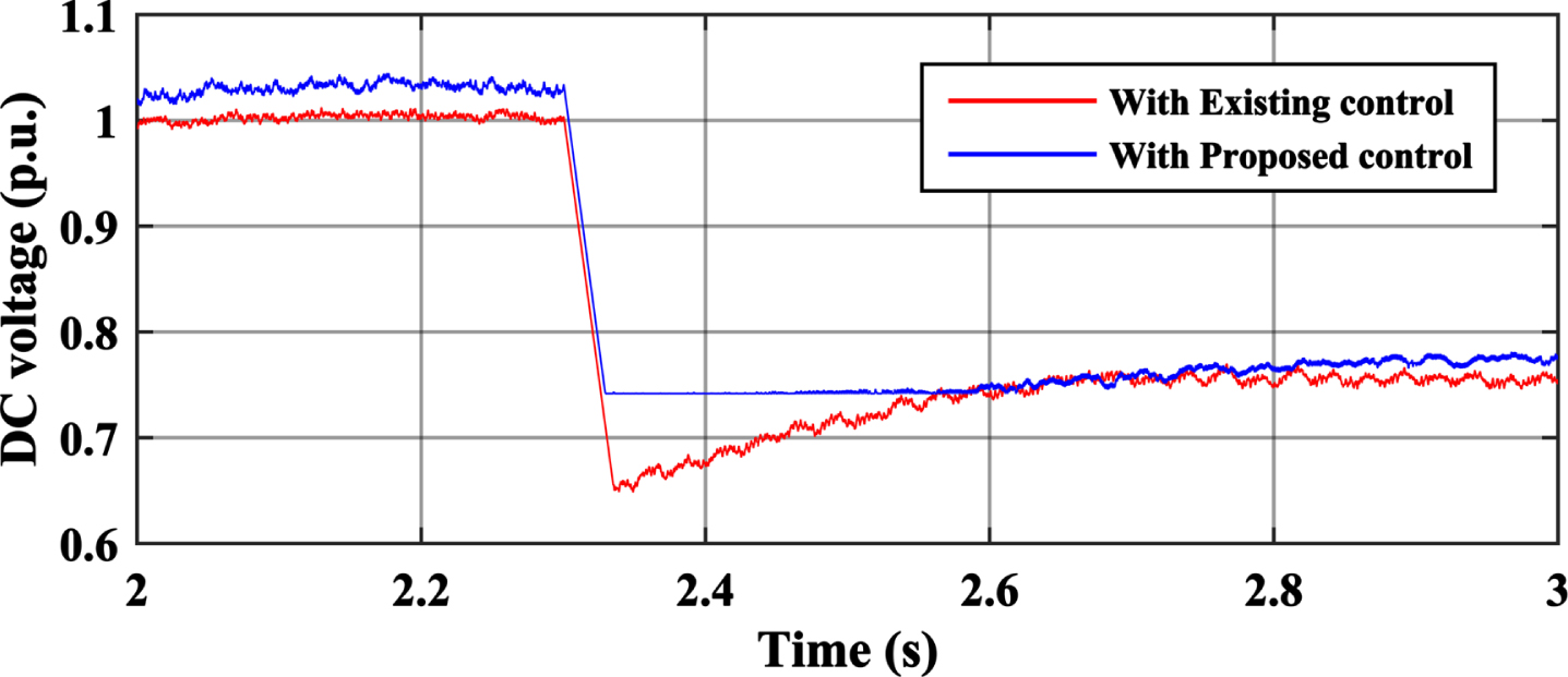
The DC link voltage in Fig. 8 decreases to release the energy stored by the supercapacitor (SC). The voltage drop is limited by the lower limit of the voltage limiter to support the virtual inertia /frequency control system.
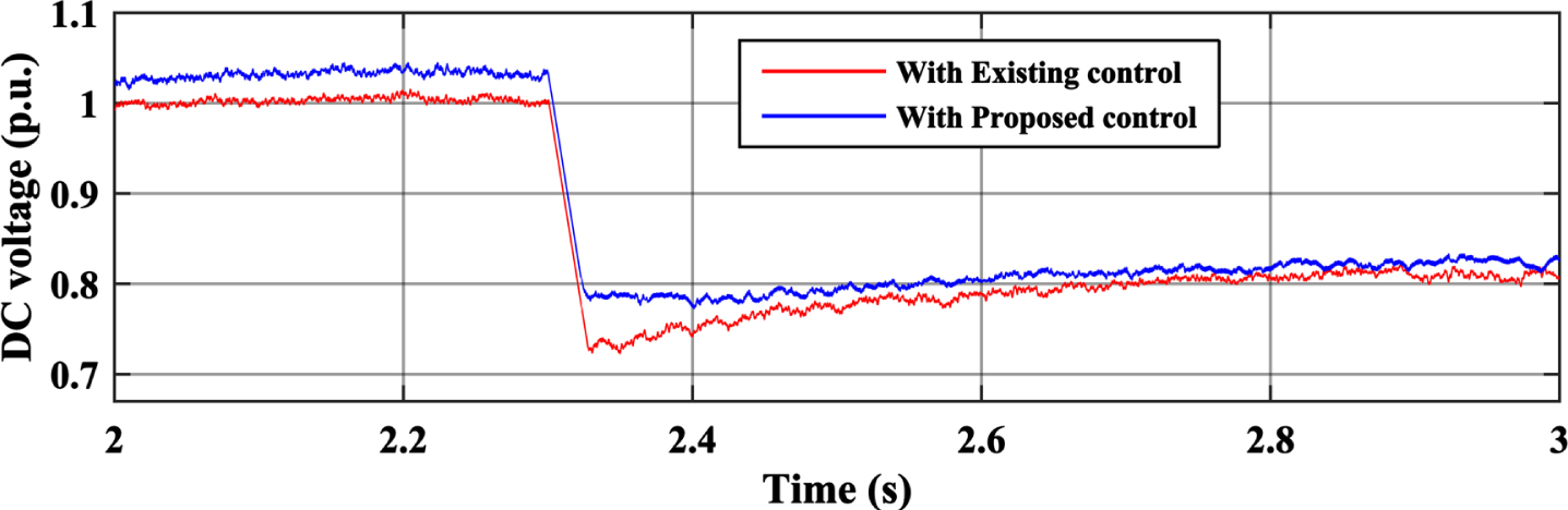
Effect of sudden load increment on DC voltage.
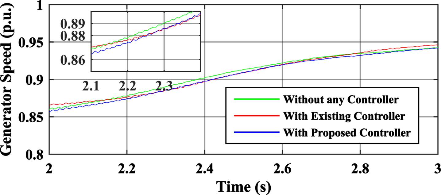
Figure 9 shows that the variation in speed is minimal. It means the supercapacitor (SC) & control system support the machine’s rotational (mechanical) inertia. Both the systems existing & proposed efficiently work to support rotating inertia.
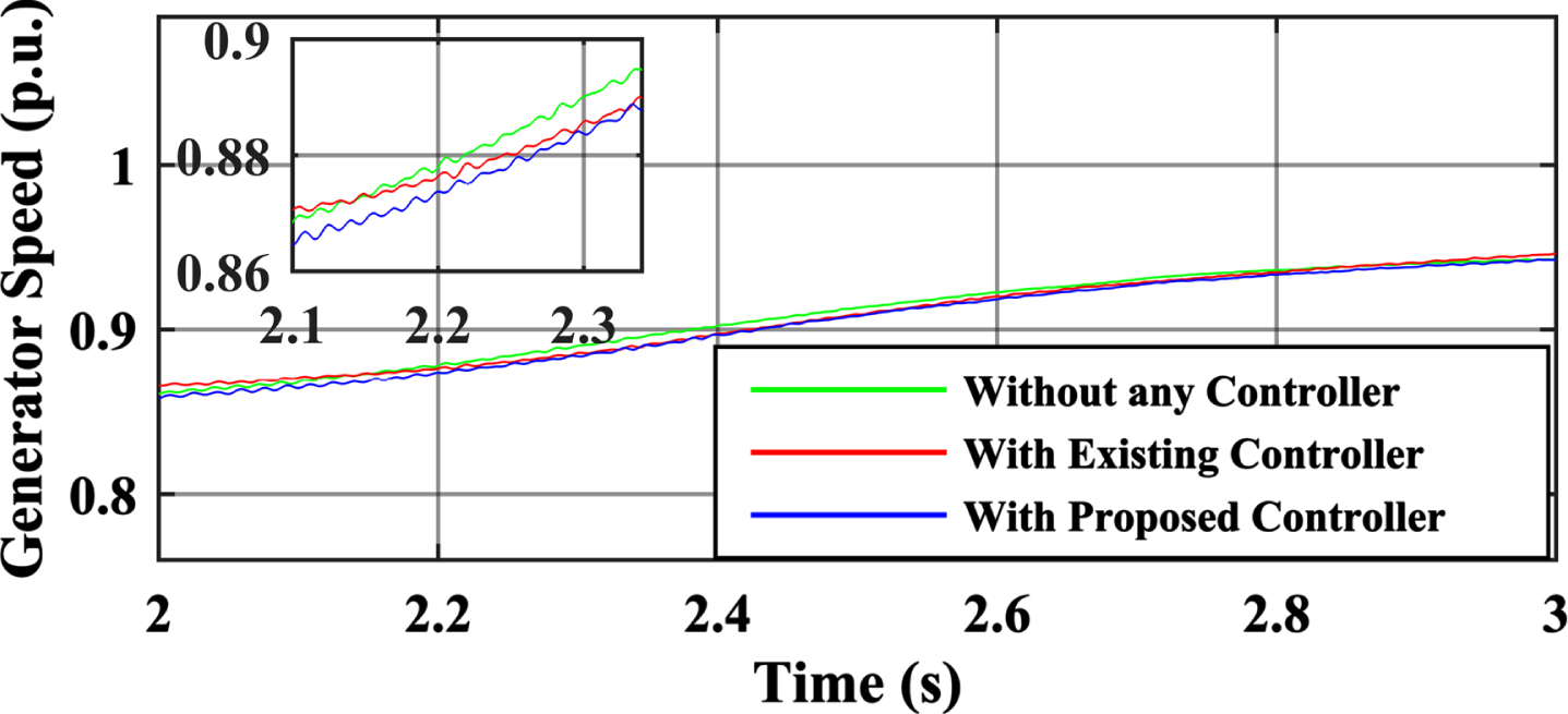
Generator speed during the sudden load raise.
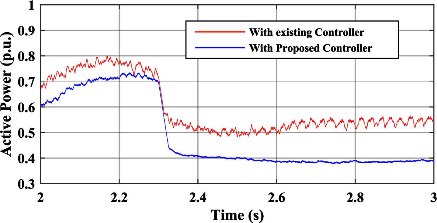
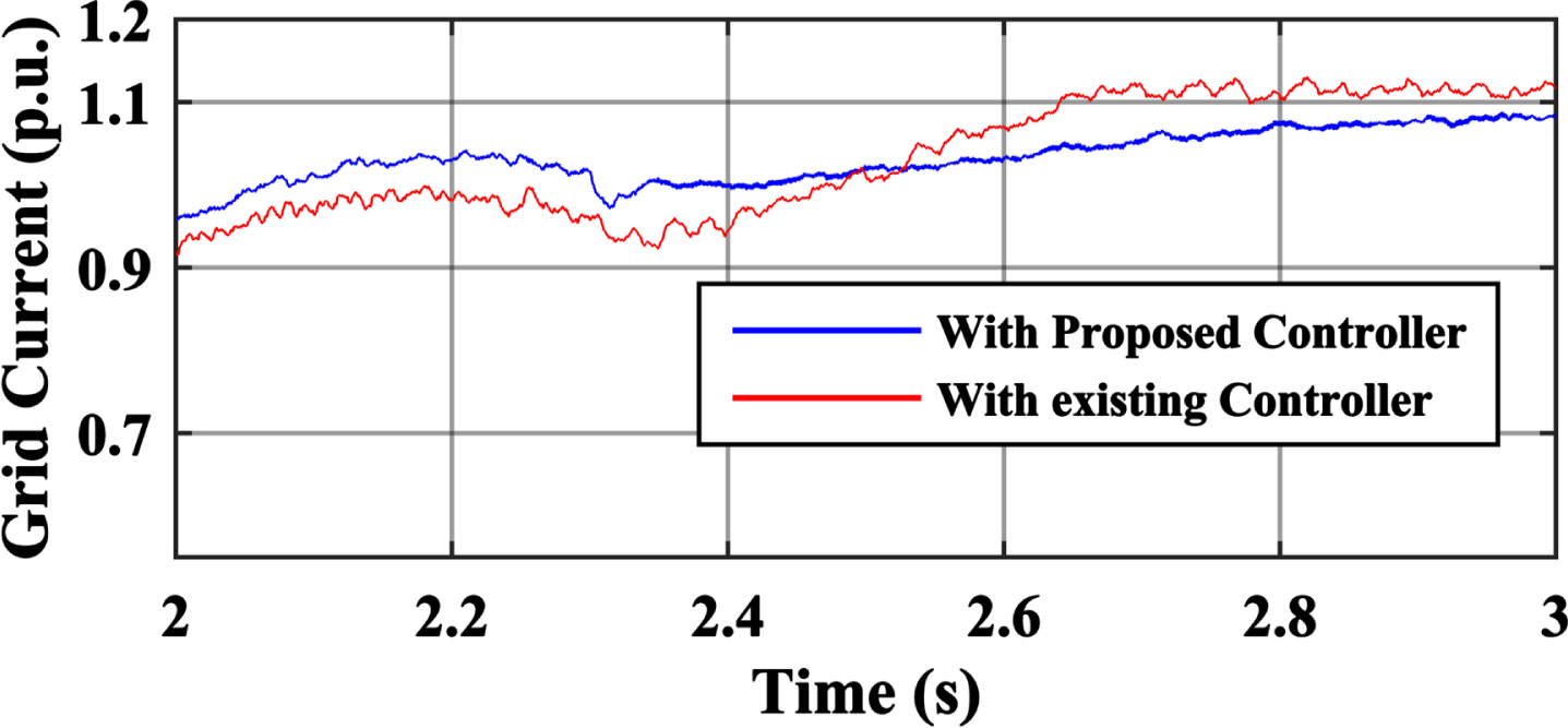
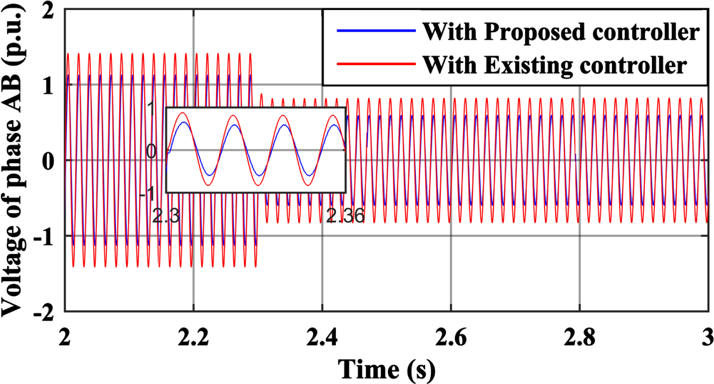
The other parameters like active power, grid current & voltage of the grid are shown in Fig. 10, 11 & 12, respectively. The voltage profile shows the line-line voltage (ab), and the current is the magnitude of the three-phase current.
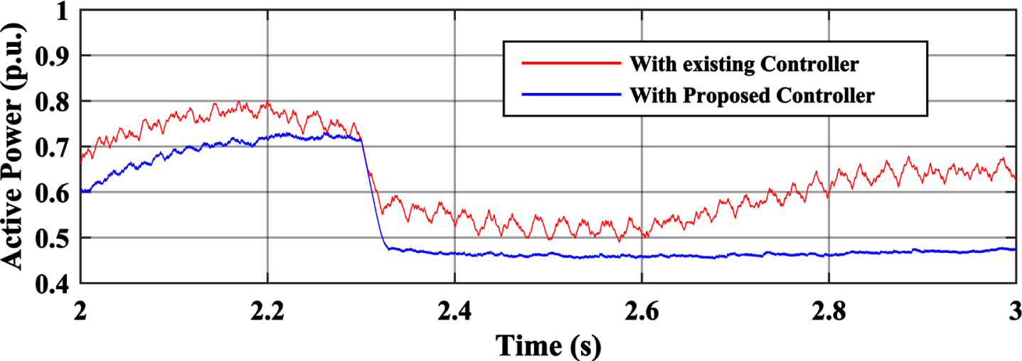
Active power response due to sudden load increment.
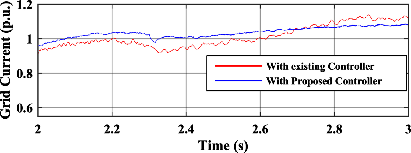
The magnitude of a three-phase grid current during a frequency dip event.
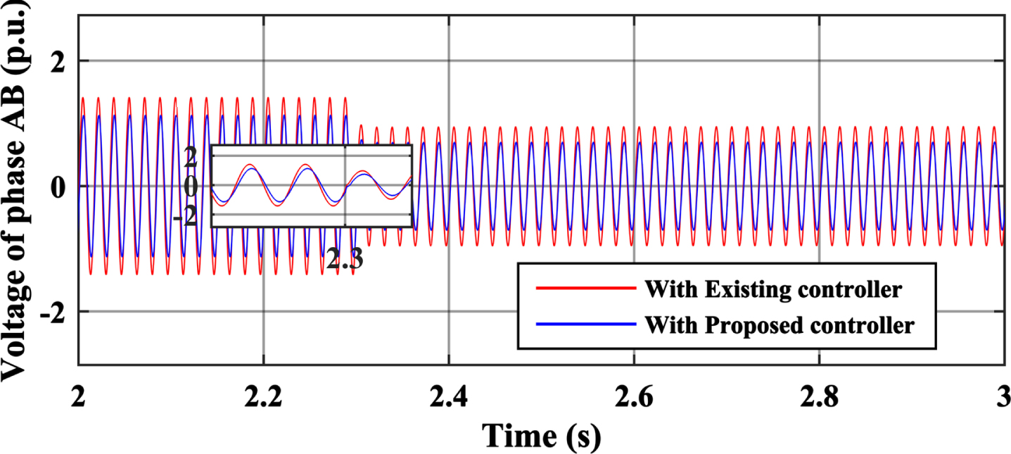
The voltage of phase AB during sudden load increment.
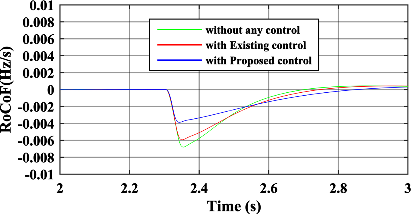
Figure 20 shows that without any control and existing control technique, the RoCoF is improved with proposed system. Proposed system have low RoCoF because of energy supported SC. Table 3 shows the comparative summary of the existing virtual inertia support system and the proposed VIS system at sudden load increment.
Table 2 shows the comparative summary of the existing virtual inertia support system and the proposed VIS system. The table has the parameters like frequency dip peak during the load increment of 57.1% of normal load. The other parameters like settling time indicate that the proposed system has a better settling time, i.e., the system is more effective in supporting virtual inertia.
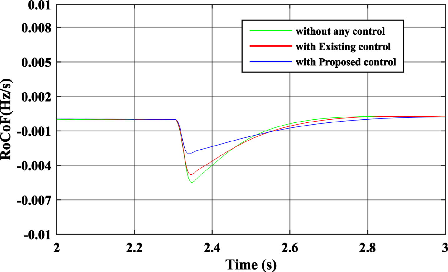
RoCoF at sudden load increment.
An comparison of frequency response without any control, with [22] existing control scheme and with the proposed FCS system under the condition of load increment
The FCS-based system has greater control over the frequency under load variation, as shown in Table 2 and Fig. 7.
Case: 1(b) –Sudden Load Increment (88.88%)
The nominal load of 315 MW and 105 Mvar is connected to the system. The load increment of P = 280 MW (88.88%) and Q = 60 Mvar increase at bus 9 on time t = 2.3 sec., and it indicates from Fig. 14 that the frequency control system (FCS) is working properly. The FCS-based system has a fast recovery of frequency dip, allowing a minor dip in frequency than without an FCS support system and compared with the existing system [22] of the proposed control strategies. From Fig. 14, it is clear that the frequency change Δf is 0.004pu with the proposed FCS system, while the existing system has produced the Δf is 0.006pu.
Frequency of the system in case of sudden load increment (up to 88.8%).
The DC link voltage in Fig. 15 decreases to release the energy stored by the supercapacitor (SC). The voltage drop is limited by the lower limit of the voltage limiter to support the virtual inertia /frequency control system.
Effect of sudden load increment on DC voltage (up to 88.8%).
Figure 16 shows that the variation in speed is minimal. It means the supercapacitor (SC) & control system support the machine’s rotational (mechanical) inertia. Both the systems existing & proposed efficiently work to support rotating inertia.
Generator speed during the sudden load raise (up to 88.8%).
The other parameters like active power, grid current & voltage of the grid are shown in Fig. 17, 18 & 19,respectively. The voltage profile shows the line-line voltage (ab), and the current is the magnitude of the three-phase current.
Active power response due to sudden load increment (up to 88.8%).
The magnitude of a three-phase grid current during a frequency dip event (up to 88.8% load increment).
The voltage of phase AB during sudden load increment(up to 88.8%).
Figure 13 shows that without any control and existing control technique, the RoCoF is improved with proposed system. Proposed system have low RoCoF because of energy supported SC.
RoCoF at sudden load increment (up to 88.8%).
In case of sudden load decrement, the decrement loads disconnect from bus no 5 of 125 MW & 50 Mvar and from bus no 6 of 50 MW & 30 Mvar. A total of 175 MW and 80 Mvar are disconnected suddenly at time t = 4.2 sec. The sudden load decrease has an impact on the frequency to rise. The proposed system limits the frequency rise compared to the existing frequency control system. The proposed system has a fast recovery system. Figure 21 shows the frequency of the system in case of sudden load decrement.
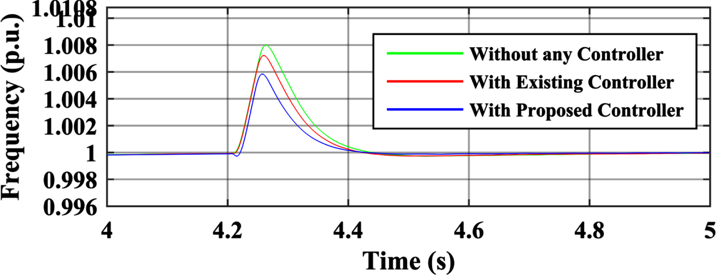
Frequency of the system in case of sudden load decrement.
Figure 22 shows that the DC bus voltage rises to a significant level. The response shows that the proposed system has limited the DC voltage & it is possible with the help of a voltage limiter in the proposed system. The DC voltage limit to the maximum limit of 1.2pu. Although the existing system does not limits the voltage rise.
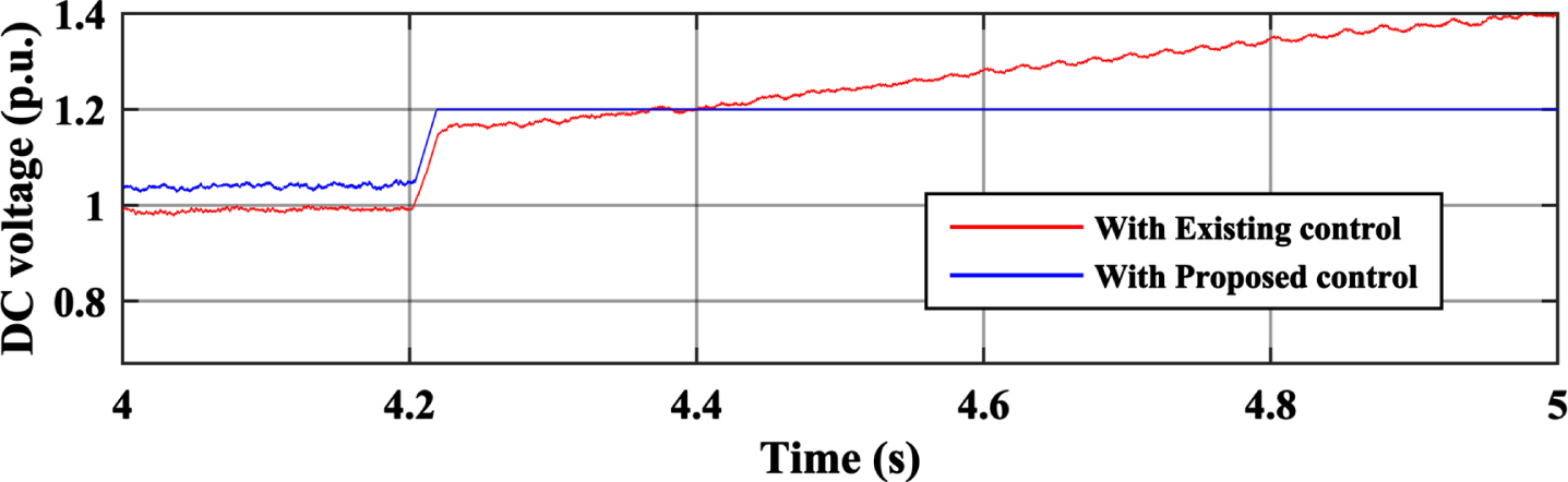
Effect of sudden load decrement on DC voltage.
Figure 23 shows that the variation in speed is minimal. It means the supercapacitor (SC) & control system support the machine’s rotational (mechanical) inertia.
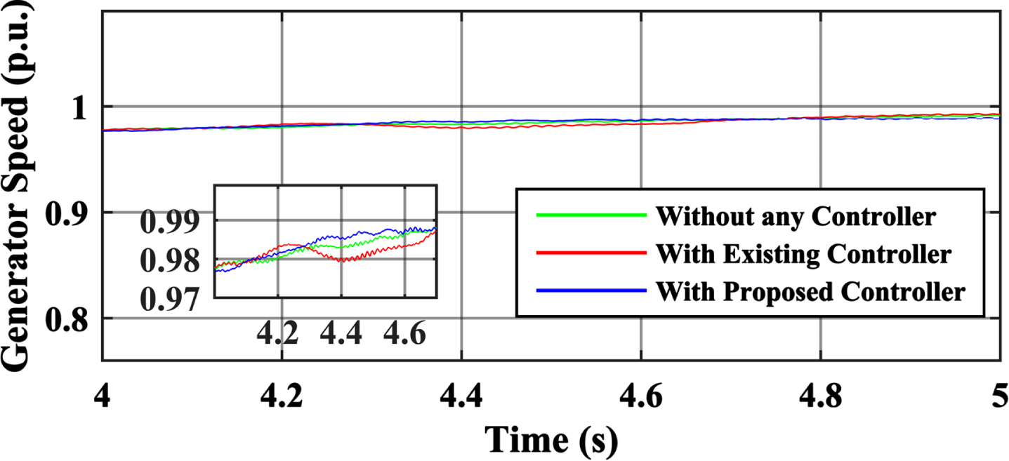
Generator speed during the sudden load decrement.
Figure 24, 25 & 26represent the parameters like active power, grid current, and voltage during the frequency rise condition.
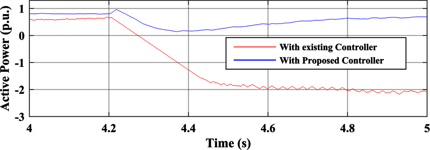
Active power response due to sudden load decrement.
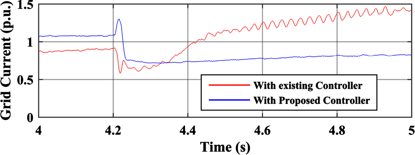
The magnitude of a three-phase grid current during a frequency rise event.
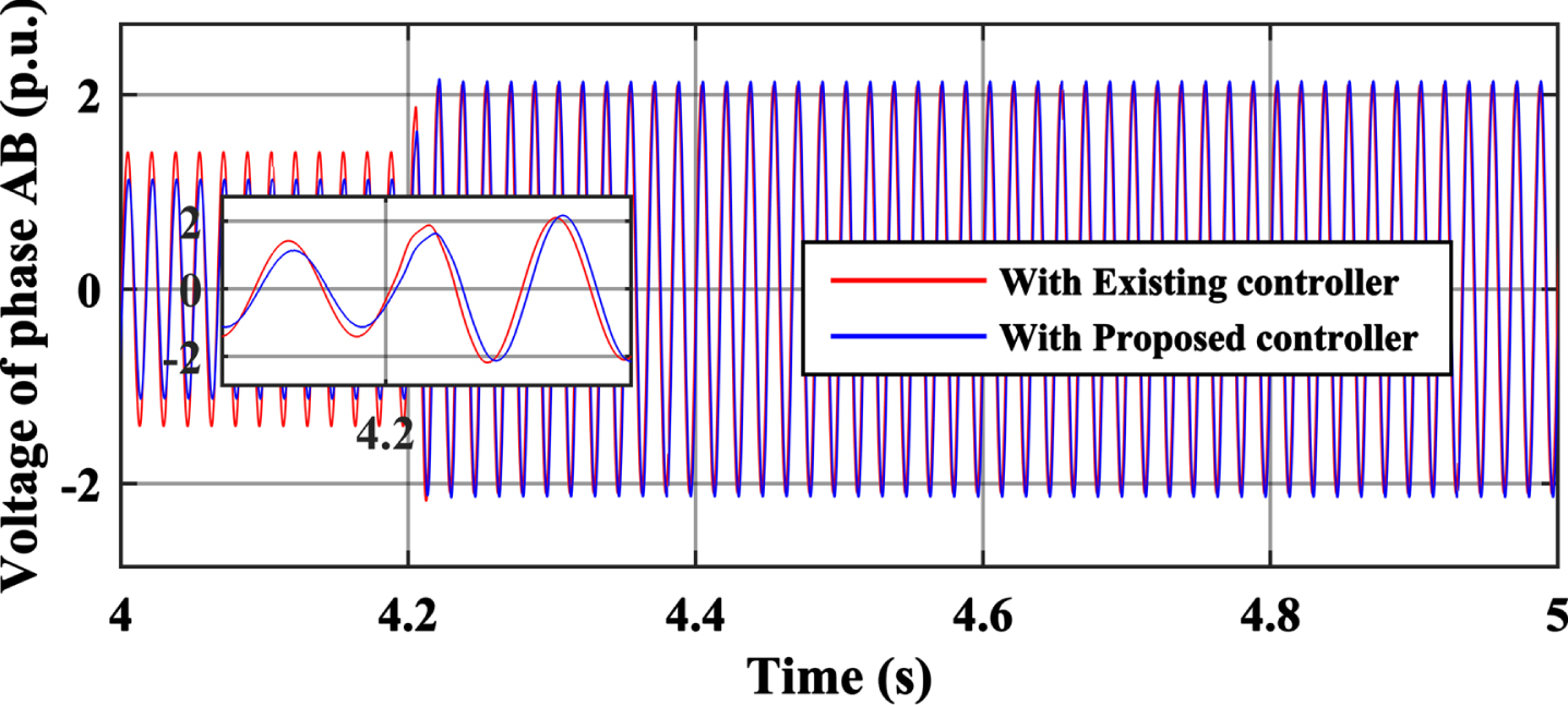
The voltage of phase AB during sudden load cut-off.
Figure 27 shows that without any control and existing control technique, the RoCoF is improved with proposed system. Proposed system have low RoCoF because of energy supported SC.
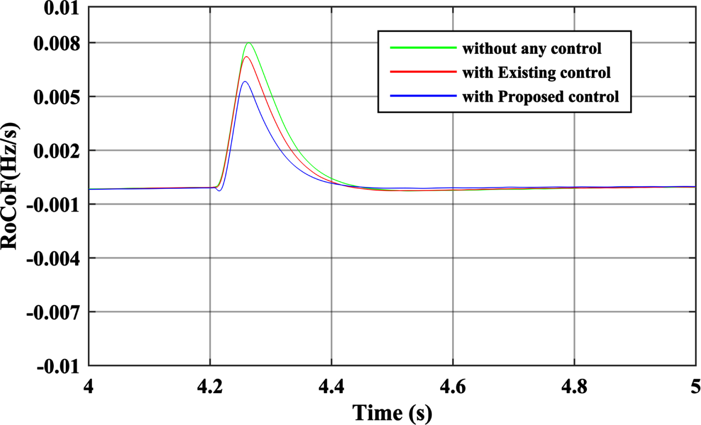
RoCoF at sudden load decrement.
Figure 28 shows a real-time view of the grid voltage of phase AB with & without the FCS system.
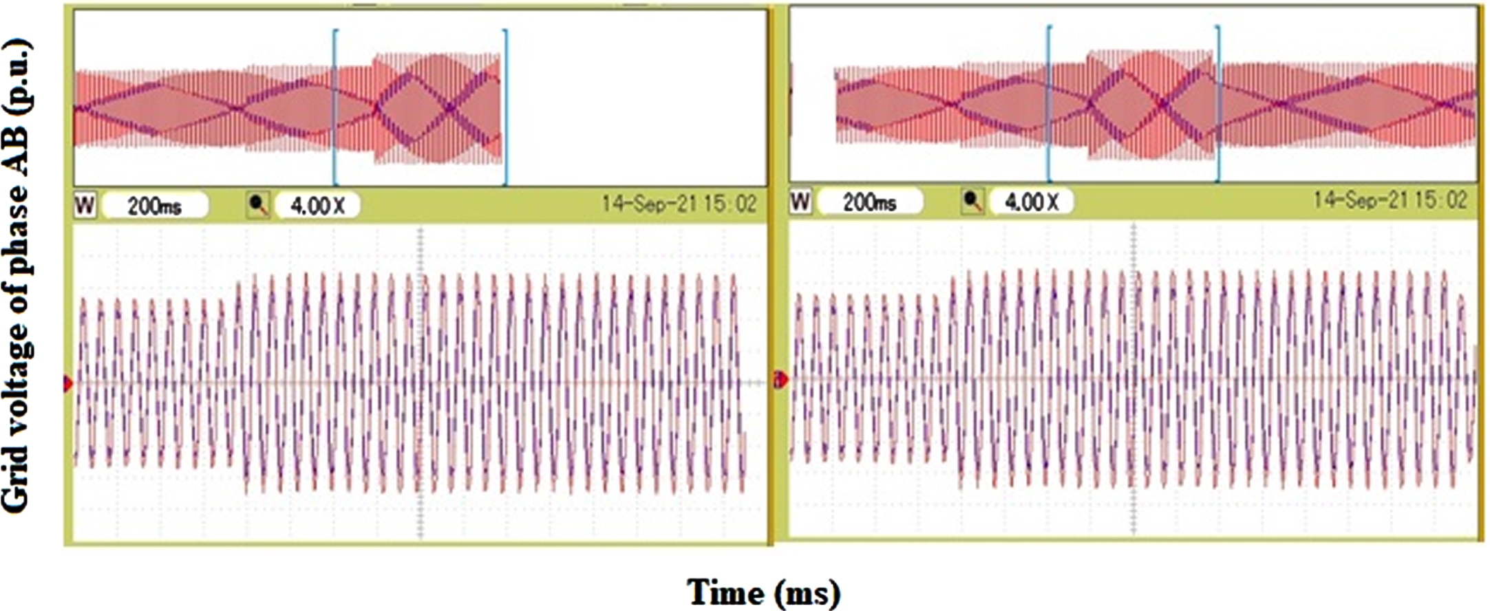
Real-time view of grid voltage of phase AB with & without FCS system.
Table 4 shows the comparative statement of the two systems under the frequency rise event. This table shows the effectiveness of the proposed system. In the frequency rise case, the change in frequency isΔf=0.006pu.
An comparison of frequency response without any control, with [22] existing control scheme and with the proposed FCS system under the condition of load increment upto 88%
Here the simulation is carried out in the condition of faults like L-L, LLL-G, LL-G, and LLL, where G stands for the ground and L stands for the line. The fault occurs at time t = 3.2 sec & fault restore at 3.5 sec. in L-L, LLG fault. The LLL-G and LLL faults occur at time t = 4 sec. & restoration of fault done at t = 4.2 sec.
Figure 29 represents the L-L fault, i.e., the fault between phases AB. Figure 29(a)contains the fault current, which shows that the fault occurs at time t = 3.2 sec & fault restore at 3.5 sec.
Simulation results of line-to-line fault,[a]-Faults current, [b]-Frequency of the system,[c]-DC link voltage,[d]-Active power,[e]-Grid current,[f]-Grid voltage phase AB.
In Fig. 29(b),the dip in frequency and the disturbance in frequency are less than the existing frequency control system. Figure 29(c)shows the DC-link voltage changes to 0.7pu. But the proposed system voltage limiter limits it to the lower limit. The active power, current, and voltage are shown in Fig. 29(d), (e), and (f),respectively.
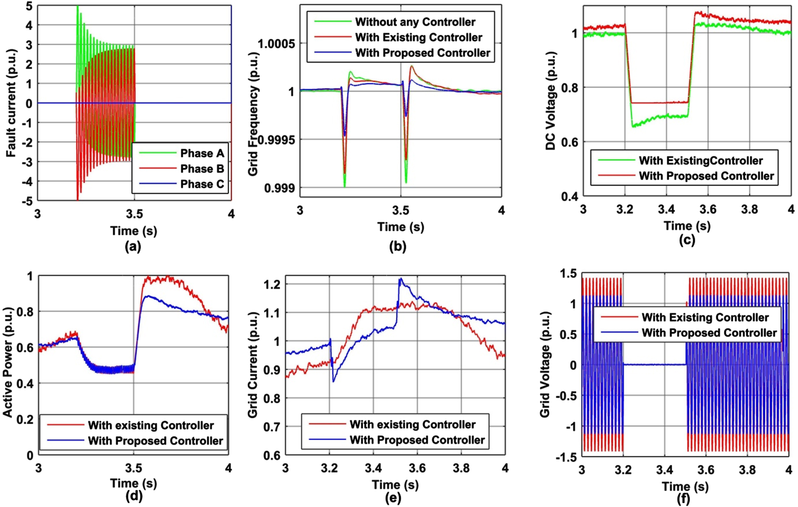
Figure 30 represents the LL-G faults, i.e., fault between phases ABG. Figure 30(a)contains the fault current, which shows that the fault occurs at time t = 3.2 sec & fault restore at 3.5 sec.
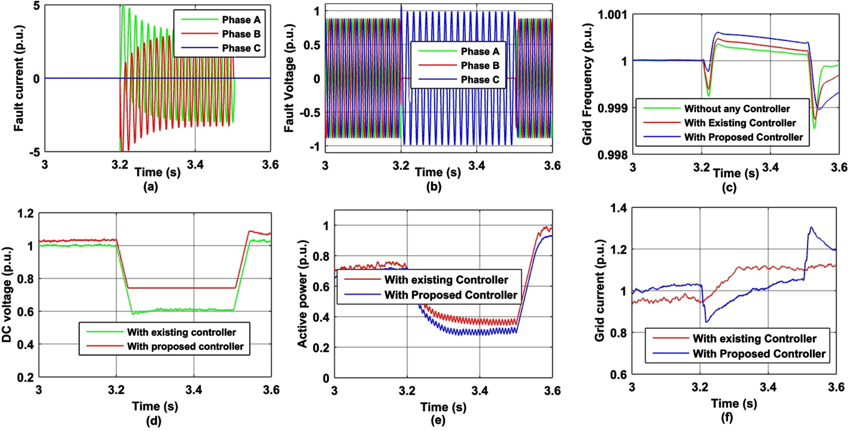
Simulation results under phase LL-G fault,[a]-Faults current, [b]- Fault voltage phase AB-G,[c]-Frequency of the system,[d]-DC link voltage, [e]-Active power,[e]-Grid current.
In Fig. 30(c),the disturbance in frequency is less than the existing frequency control system. DC-link voltage is lowered to 0.6 pu, shown in Fig. 30(d),but the proposed system voltage limiter limits it to the lower limit. Figure 30(b), (e), and (f)shows the fault voltage, active power & grid current, respectively.
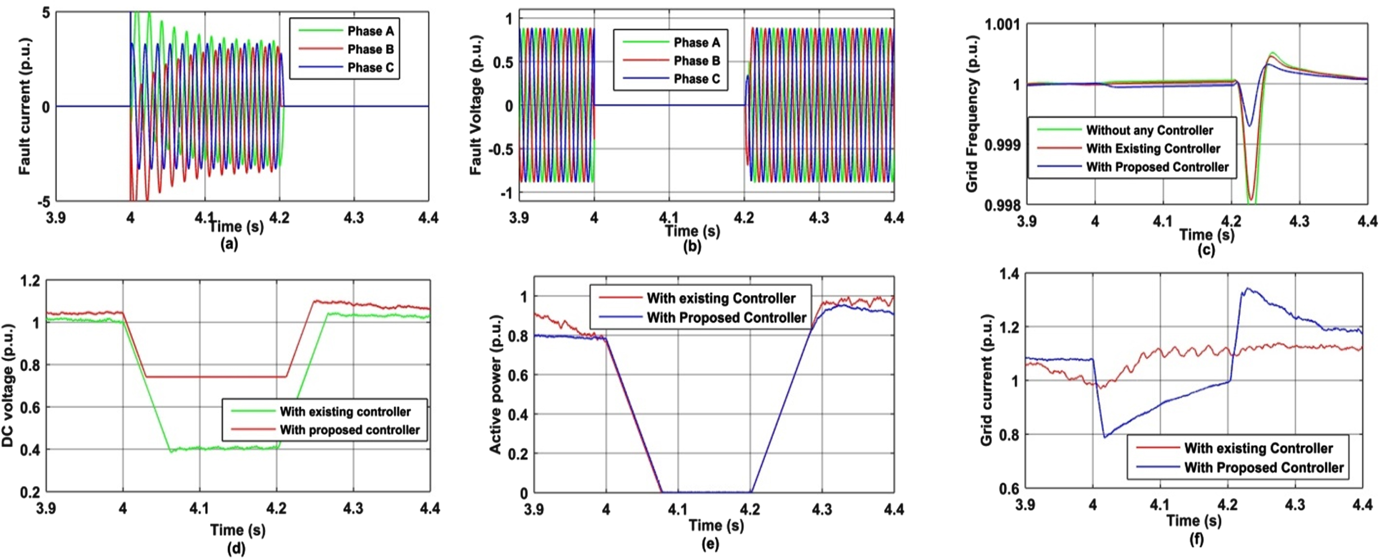
In Fig. 31, the response of the simulated result is under the fault condition of LLL-G faults. Figure 31(a)contains the fault current, showing that the LLL-G fault occurs at t = 4 sec. & fault restores at 4.2 sec.
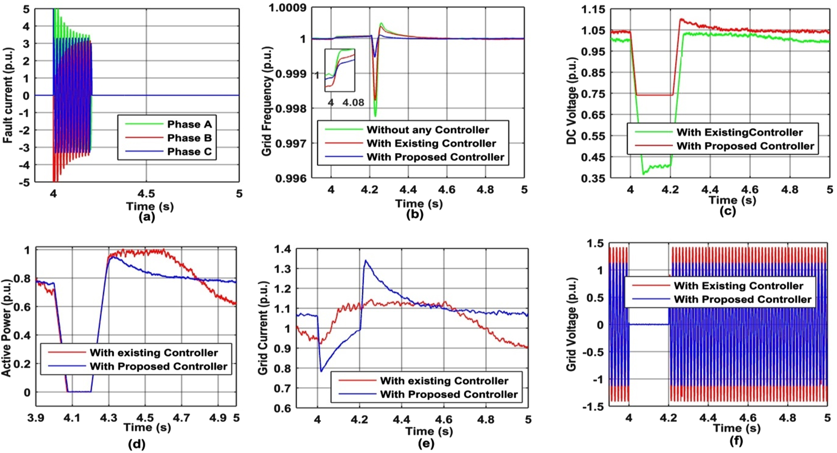
Simulation results under phase LLL-G fault,[a]-Faults current, [b]-Frequency of the system,[c]-DC link voltage,[d]-Active power,[e]-Grid current,[f]-Grid voltage phase ABC-G.
In Fig. 31(b),the frequency at fault occurs is shown in the expanded window at t = 4 sec. The DC voltage drops to a deficient level while the proposed system holds it to a minimum level shown in Fig. 31(c).Figure 31 (d), (e), and (f)shows the active power, grid current, and grid voltage, respectively.
In Fig. 32, the response of the simulated result is under the fault condition of LLL faults. Figure 32(a)contains the fault current, showing that the LLL fault occurs at t = 4 sec. & fault restores at 4.2 sec. Figure 32(c)shows the frequency at fault occurs at t = 4 sec. The DC voltage drops to a deficient level while the proposed system holds it to a minimum level shown in Fig. 32(d).Figure 32(b), (e), and (f)show the fault voltage, active power & grid current at the LLL fault.
Simulation results under phase LLL fault,[a]-Faults current, [b]- Fault voltage phase ABC,[c]-Frequency of the system,[d]-DC link voltage, [e]-Active power, [f]-Grid current.
Figure 33 shows the system HIL setup of the OPAL-RT 4510 simulator.
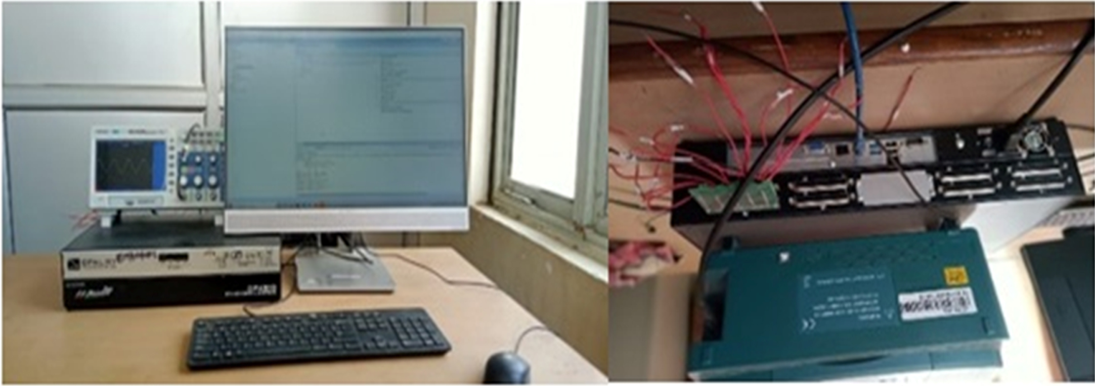
HIL setup of OPAL-RT 4510.
Table 5 shows below the parameter of SPMSG for the simulation model.
Comparison of frequency response without any control, with [22] existing control scheme and with the proposed FCS system under the condition of load decrement
SPMSG parameters
SPMSG-based WT is connected with the modified IEEE-9 bus test system to test the proposed FCS in this manuscript. The electrolytic capacitor replenishes with the supercapacitor to support the virtual inertia of the system. In this paper, to estimate the machine speed and rotor position, the sensorless technique (SRF-PLL) is utilized, which is used to control the machine side converter pulses and does not affect the virtual inertia support. The SRF-PLL-based estimation technique estimates the system parameter during the load transients and frequency instability. The supercapacitor controls the DC-link voltage to not exceed high value by absorbing and releasing the power to maintain the DC bus voltage.
The FCS system depends upon the FCS gain looped with the DC voltage control, providing support to the DC bus voltage. The FCS system is verified with load variations and different fault conditions. The FCS-based VIS is only implemented on the grid side support, while the existing system has rotational inertia support. The FCS system has a better ability to control frequency dip/rise. The settling time of the proposed FCS is less than 3.331 ms than the existing system & 4.771 ms without any control system in case of frequency dip condition. The settling time of the proposed FCS is less than 1.574 ms than the existing system & 2.608 ms without any control system in case of frequency rise conditions. It is observed from the above results that the proposed system has improved RoCoF. The proposed system controls the DC link voltage to prevent rise/fall, and the overall cost is less compared to the existing system. The simulation result verifies the FCS system using the MATLAB/Simulink environment. The results are cross verified by OPAL-RT 4510 real-time simulator.
Footnotes
Acknowledgment
The authors are grateful to the Electrical Engineering Department of Rajkiya Engineering College (REC) Mainpuri, Uttar Pradesh, for providing the OPAL-RT 4510 real-time simulator facility to perform our research work.