
Abstract
With the superior development of technology, mobile robots have become an essential part of humans’ daily life. Consequently, interacting and dealing with them pushes us to develop and propose different suitable Human-Robot Interaction (HRI) systems that can detect the interacted user’s actions and achieve the desired output in real-time. In this paper, we propose a closed-loop smart mechanism for two main agents: the hand gloves’ controller and the mobile robot. To be more specific, the developed model employs flex sensors to measure the curve of the finger. The sensor signals are then processed by aiding the Hedge Algebras Algorithm to control the movement direction and customize the speed of the mobile robot via wireless communication. Numerical simulation and experiments demonstrate that the mobile robot could operate reliably, respond rapidly to control signals, and vary its speed continually based on the different finger gestures. Besides, the control results are also compared with those obtained from the traditional fuzzy controller to prove the superiority and efficiency of the proposed method.
Introduction
In recent years, mobile robots have been a popular area of study, garnering considerable interest [1–5]. It is envisaged that the motion control of such robots would not only navigate within human-robot interaction but will also respect human actions and intents. The mobile robot must be capable of human identification, real-time localization, and motion planning to complete a variety of difficult tasks assigned by humans. However, the unpredictability of human behavior makes it difficult to follow human body movements and analyze body language. In addition, slippage between the ground and the wheel produces cumulative mistakes in odometer placement, leading to erroneous robot feedback behavior. Moreover, owing to the nonholonomic system features of mobile robots [6, 7], the motion planning challenges of stability in disturbance settings [8] are significantly complicated. By integrating input from many modalities to accurately decipher human intentions and/or gestures, some contemporary systems strive to overcome the various control and system integration issues. The hedge algebra theory was created in 1990 [9] to represent the order-based semantics of words in term domains of linguistic variables. The authors of [10] note that the construction of the hedge-algebra-based controller (HAC) is similar to that of the standard FC but simpler and more practical. As a result, the HAC has been utilized in optimal fuzzy control of an inverted pendulum [11], active vibration control of building structures subjected to seismic excitations [12–14], voltage control of a self-excited induction generator [15], and control robotic to address the difficulty of its dynamical identification [16, 17]. However, it has not yet been implemented for mobile robot speed control. In [18], an electronic glove equipped with flex sensors along the fingers was designed to control the mobile robot’s behavior. By integrating the information of the finger-bending movements with the fuzzy logic method, the mobile robot could be navigated and controlled over a medium distance. In [19], an obstacle avoidance system based on fuzzy logic control was proposed for mobile robots. The FLC controller served as both an ultrasonic sensor input and a distance sensor. The potentiometer was used to replicate the input voltage, while the DC motor speed represented the output. Zhao et al. [20] built a speed rate controller based on muscle electrical waveforms to enhance the human-robot interaction possibilities in the industrial environment. To be more detailed, the muscle information was first collected continuously and then added to the interaction based on unity. The next stage included modifying the mapping speed ratio using an algorithm based on the electromyography data provided. In [21], a hand gesture identification method is designed based on inertial measurement unit (IMU) data integrated on the smartphone. More specifically, the integrated inertial measuring unit monitors muscle contractions during posture shifts, creating waveform signatures. A competitive layer votes the class with higher probability and identifies the gesture after calculating the correlation between measured and template patterns. In [22], an innovative flexible endoscope foot-controlled teleoperation robotic system. Dedicated interfaces relate natural foot patterns to endoscope motions. The robotic system controls four-degree-of-freedom movements with typical gastrointestinal endoscopes. However, the actuators set up on the system still have high latency and slow response. In [23], a soft haptic to navigate a drone in simulation environment is designed based on the flying sensation from real human body. To estimate air pouch inner pressure, connection point, and cable location, a pouch device was modeled and simulated. Throughout the simulation, a selection of flight cases produced favorable outcomes for this form of experiment. Nevertheless, due to the limitations of the simulation platform, the aerodynamic forces (lift, drag, external disturbances such as wind surges, etc.) and the friction coefficient be-tween the pouch and the epidermis could not be implemented as accurately as in reality. Meghana et al. [24] presented a voice and hand gesture-operated robot controller. This creates the link between technology and humanity for communication. This project’s objective is to improve the robot’s comprehensive security and to streamline its control mechanism. Jared et al. [25] presented a mobile mixed-reality interface strategy for enhancing human-robot interactions in shared spaces. Ivo Stancic et al. [26] proposed an inertial-sensoe-based system capable of communicating with a robot at a distance of up to 250 meters. Utilizing hand gestures, the research is implemented in mobile robots. However, the system’s components were expensive, and the controller may also be expensive. In the study, neither the cost of the system’s apparatus nor the controller’s response time were mentioned. Bo Zhang and Guanglong Du proposed a collaborative robot gesture system in [27]. The dual automaton can be organically interacted with using both hands. Using a weighted fusion algorithm, the sensor data were combined.
Due to the relevance and advantages outlined above, a new controller using hand gestures and wireless protocol is presented for mobile robot mobility in varied environments. Compared to previous work, the main contributions of this research work are as follows: It is noticed that the nature of HAC controller is based on fuzzy theory but is more explicit and advanced. By using the HA Algorithm, the semantic numerical values of these linguistic parameters could be determined using a quantitative semantic mapping based on a fuzzy parameter for each linguistic variable. The linguistic values are inspected continuously based on rigorous mathematical arguments and the inherent semantic ordering of them. Hence, the adaptability of data is significantly enhanced. The proposed system could use efficient data fusion and optimal encoding techniques to incorporate hand motion from the HAC controller while improving energy efficiency, safety, and usability through Bluetooth connection. In comparison to the FLC controller, the experimental results demonstrate that the HAC controller shows better and more complete control. The robot executes reliably and closely follows the instruction signal with minimal latencies.
Theoretical background
The motion of the robot is controlled by hand gestures, as seen in Fig. 1. To be more specific, when the fingers bend, the resistance will change, and the motor’s speed is dependent on the degree of sensor bending.
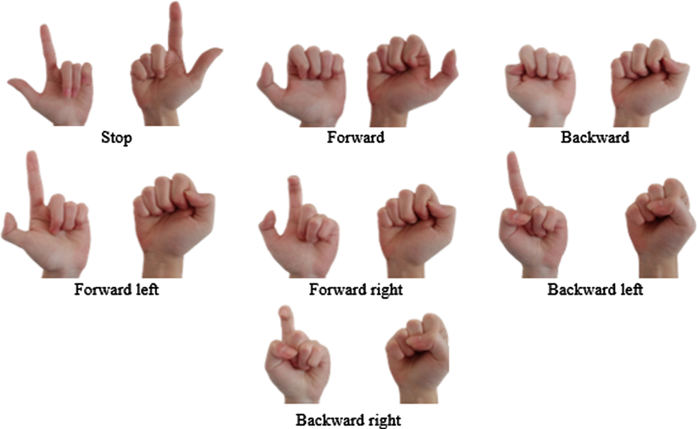
The hand gestures appropriate to robot motion.
In the sense of language labels, it can be divided into five different statuses: Very negative, negative, Little negative, Little positive, Positive, and Very positive. Thus, a new perspective is designed as the language set can be modeled with a posset (partially ordered set) - an ordered structure based on semantics.
Consider the amplitude of oscillation as a linguistic variable, and X is the set of those linguistic values. It is assumed that the linguistic elements used to represent “The Oscillation Amplitude” are “very” and “little” combined with negative and positive state. Hence, the function of X is defined as follows:
To be more detailed, the assemblage of {0 ; W ; 1} is used to determine a set of linguistic values of “The Oscillation Amplitude”, where 0, W, and 1 are presented for “Very negative”, “Neutral”, and “Very positive”.
A term-domain X can be ordered based on the following observation: Each primary term has a sign which expresses a semantic tendency. For instance, true has a tendency of “going up”, called a positive one, and it is denoted by c+. In contrast, false has a tendency of “going down”, called a negative one, denoted by c-. As a result, the truth clause of primary term is indicated as following c+ ⩾ c-. Each hedge also has a sign. It is positive if it increases the semantic tendency of the primary terms, and it is negative if it decreases this tendency. For instance, V is positive concerning both primary terms, while L has a reverse effect, and hence it is negative. Denote by H- the set of all negative hedges and by H+ the set of all positive ones of the oscillation amplitude.
It is assumed that AX is an algebraic structure of a linguistic variable X. The formula of AX is written as:
H is is a set of algebra/hedge algebra and H = { Very, Little } = H+ ∪ H-
where: H- = { h-1, h-2, …, h-q } with (h-1 < h-2 < … h-q), H+ = { h1, h2, …, h p } with (h1 < h2 < … h p )
The symbol ≥ is ordering relation on X.
Assuming that the function fm (c-) measures the fuzziness of c-, the function μ (h-) measures the fuzziness of h-1, and the set (N, P, V, L) stands for Negative, Positive, Very, and Little, respectively. With fm (0) = fm (W) = fm (1) =0 an μ (h-) =0.5, the linguistic variables are determined as in Table 1.
The value of specific linguistic variables
The fuzziness measure of vague terms and hedges of term domains is defined as follows:
afm : X → [0, 1] is said to be a fuzziness measure of terms in X if: fm (c-) + fm (c+) =1 and ∑h∈Hfm (hu) = fm (u) for ∀ u ∈ X
This proportion does not depend on specific elements,
For each fuzziness measure fm on X, we have:
A function Sign, X = {-1, 0, 1}, is a mapping that is defined recursively as follows, for and c∈ { c-, c+ }
Let fm be a fuzziness measure on X. A semantically quantifying mapping (SQM)
It can be seen that the mapping φ is completely defined by (p+q) free parameters: one parameter of the fuzziness measure of a primary term and (p+q–1) parameters of the fuzziness measure of hedges.
To illustrate the way to compute SQMs, we consider the following example. For example: Consider a HA as G = {Negative,Positive}
where μ (Little) = α = 0.5 ; μ (Very) = β = 1 - α = 0.5, C = { 0, W, 1 } , H- = { Little } = { h-1 } , q = 1, H+ = { Very } = { h1 } , p = 1, θ = 0.5, α = 0.5, β = 0.5 (α + β = 1).
Hence:
The proposed HAC includes four state variables, (x i , i = 1 ÷4), and a control variable (u) (Fig. 2).
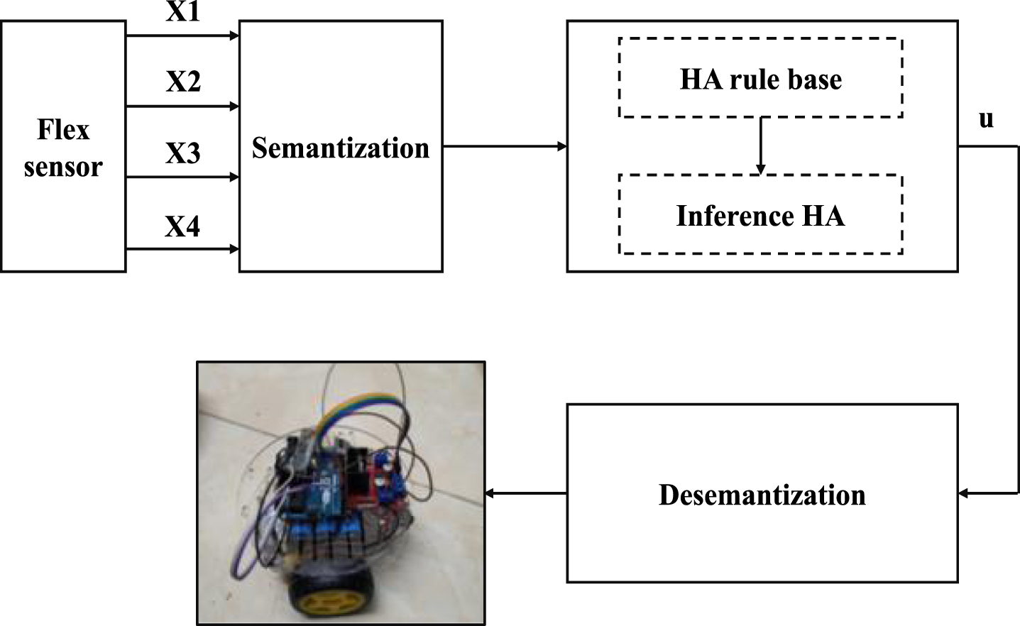
The block diagram of HA controller for the mobile robot.
Assuming: x i ∈ [- a i , a i ], and u ∈ [- b, b], the value of linguistic variables is addressed in Table 2. The normalization of the state variables mapping from the realistic domain into SQM is shown in Fig. 3a, in which x is is the value of x i in SQM. The HAC includes two rule bases (50 fuzzy rules) which are illustrated in Tables 3 and 4.
The value of state variables
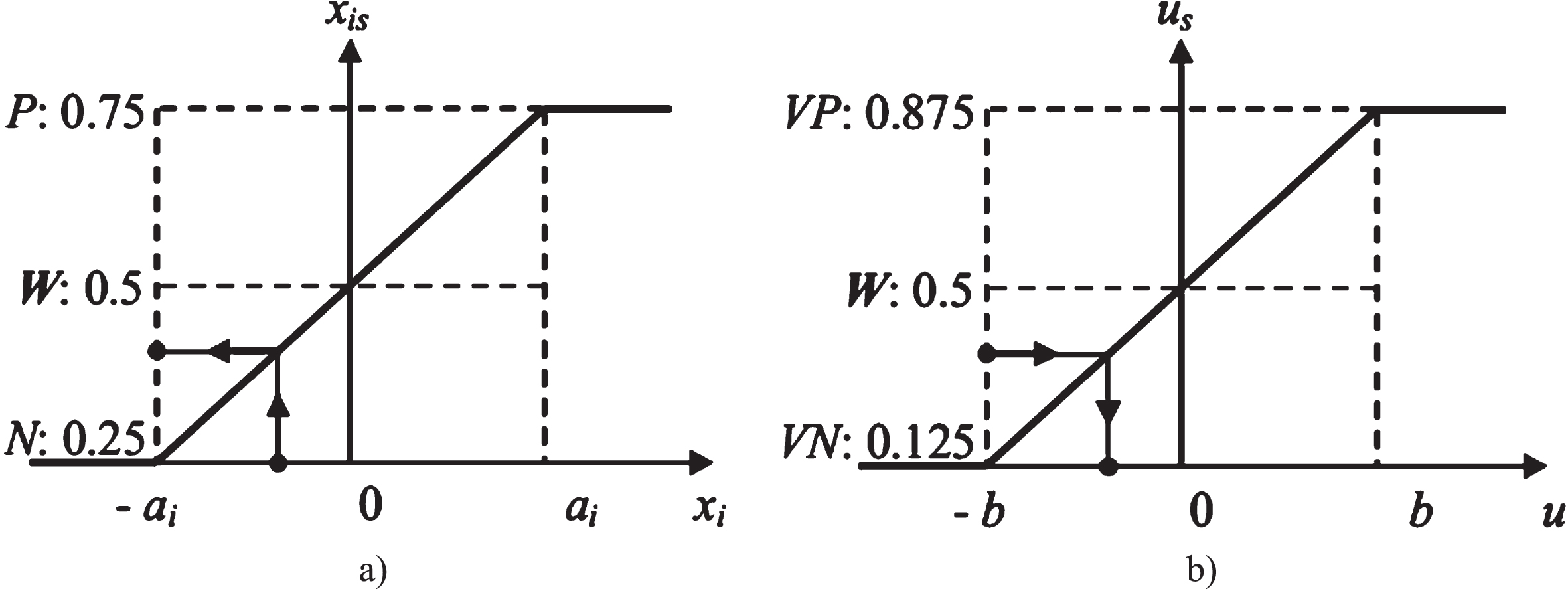
Normalization of the state variables (a) and denormalization of the control variables (b).
The surface area curve of the fuzzy controller describing the relationship between input and output signals is shown in Fig. 4.
where x1 represents the left thumb finger, x2 represents the left index finger, and x3 represents the right thumb finger, x4 represents the right index finger. After semantization procedure, the input signals are delivered from the flex sensor to the analog pins of Arduino board. This data is then calculated and standardized by the HAC. Tables 3 and 4 illustrate two HAC rule bases (50 fuzzy rules) in detail for the right finger and the left finger, respectively. The HAC output is denormalized using a MATLAB function, and the control signals are then imported into the left-wheel and right-wheel block.
Fuzzy rules for u L s of HAC for left fingers
Fuzzy rules for u R s of HAC for right fingers
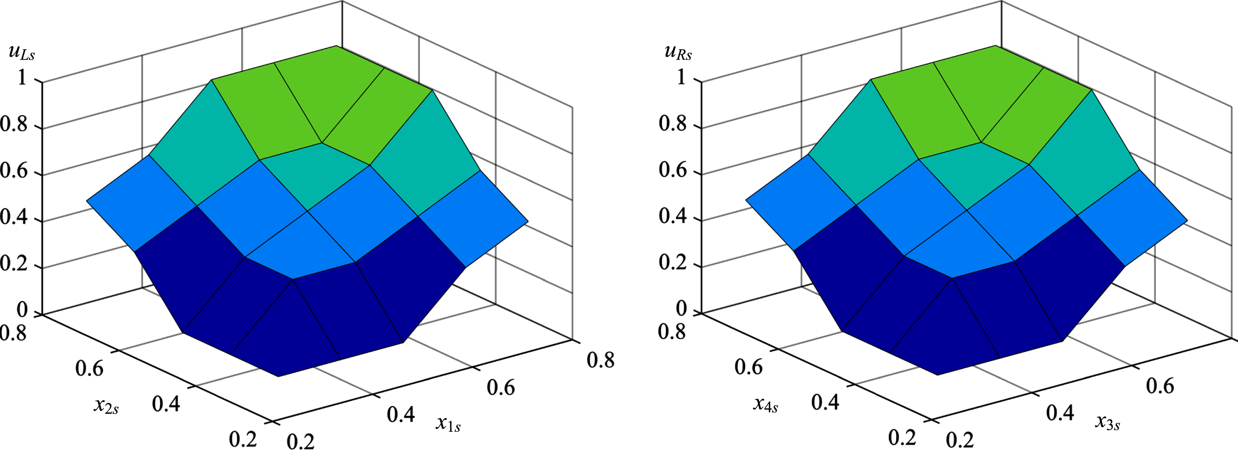
Surface area curve of the fuzzy controller.
Figure 5 shows the structures of the hardware design. The system is described in the following manner:
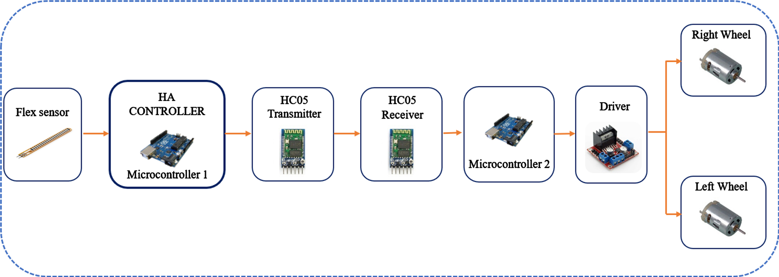
The structures of the hardware design
Initially, the finger movements alter the values of the flex sensors.
Next, the updated data is sent to the HA Controller, which functions as a signal processing module. These signals are then standardized and encoded by the HA.
In the subsequent step, the standardized data is linked to the HC05 Transmitter module and sent to the HC05 Receiver via the Bluetooth protocol.
Finally, the HC05 Receiver used these electromagnetic waves to establish control instructions for mobile robot operators.
The gloves have a flex sensor system that is directly linked to the thumb and index finger. The purpose of this design is to increase the control process’ precision and efficacy. An independent control box houses the electronic components. The design of the glove is clearly seen in Fig. 6.
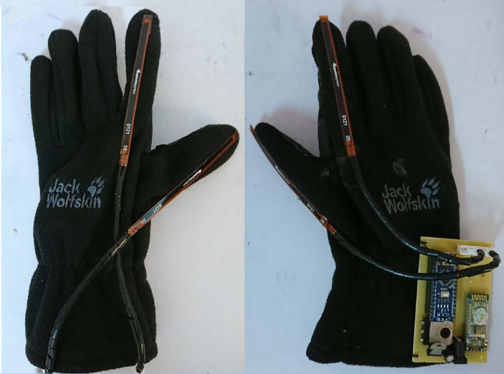
The flex sensors are attached along the finger direction.
The mobile robot’s body is built mostly of acrylic and is around 20×20×15 cm. Consequently, the robot could easily operate in restricted locations. The robot idea design is seen in Fig. 7.
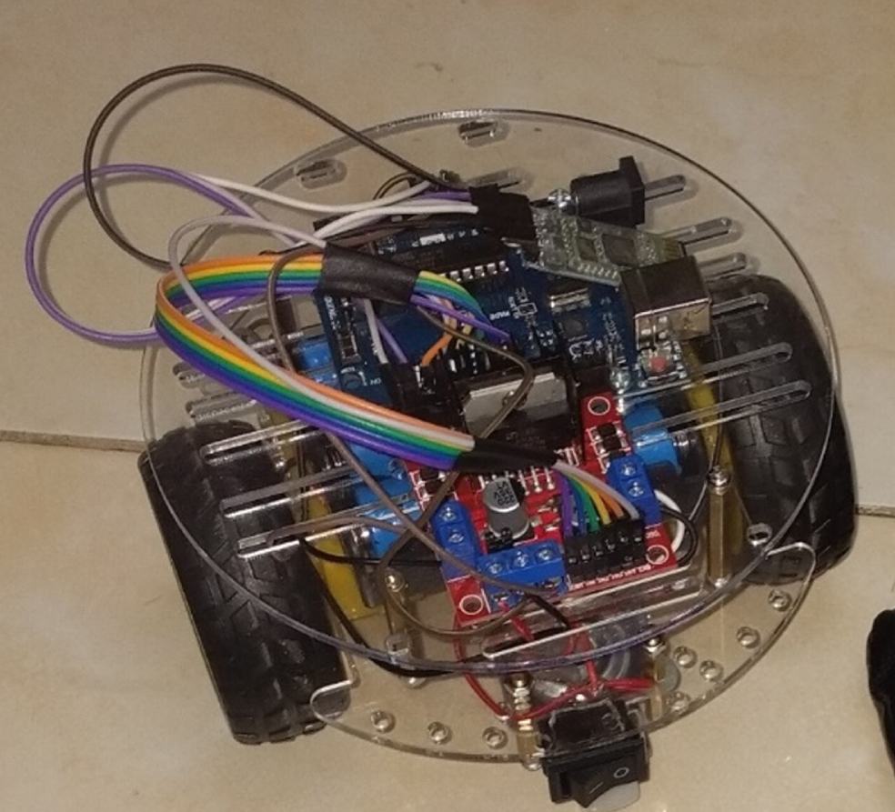
The full concept of the mobile robot.
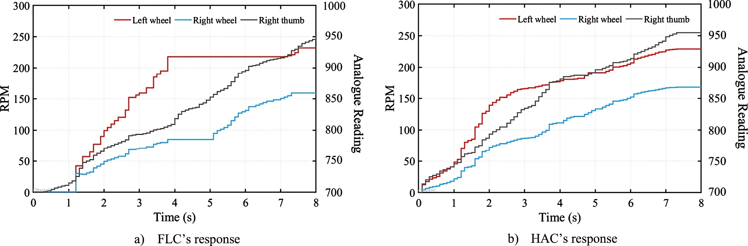
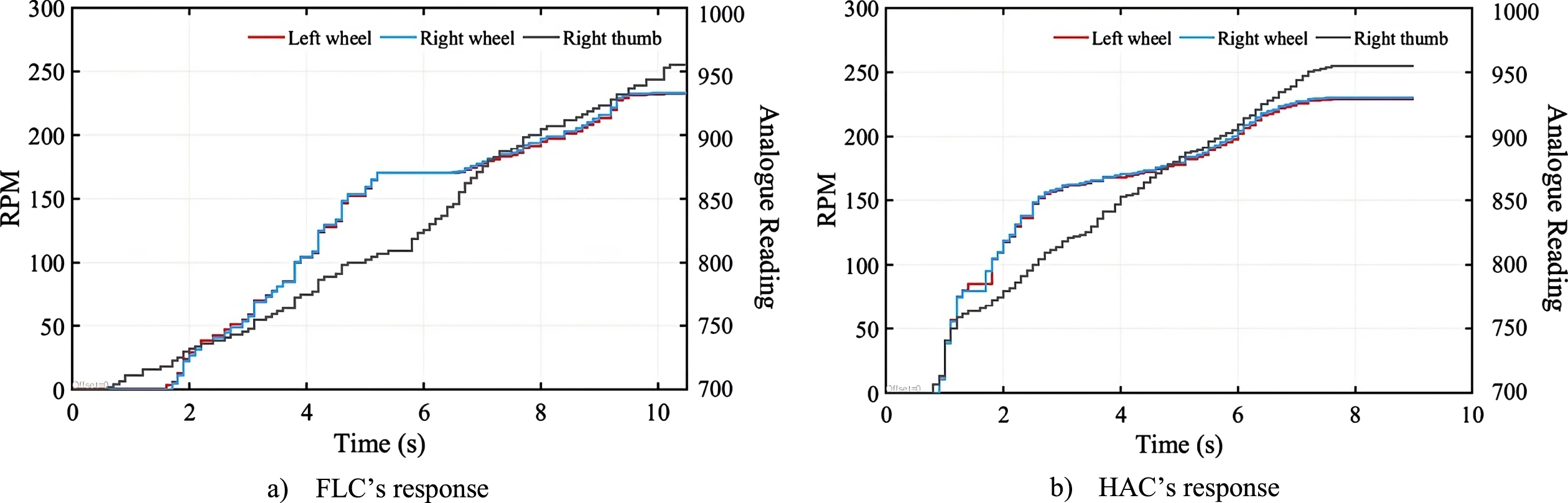
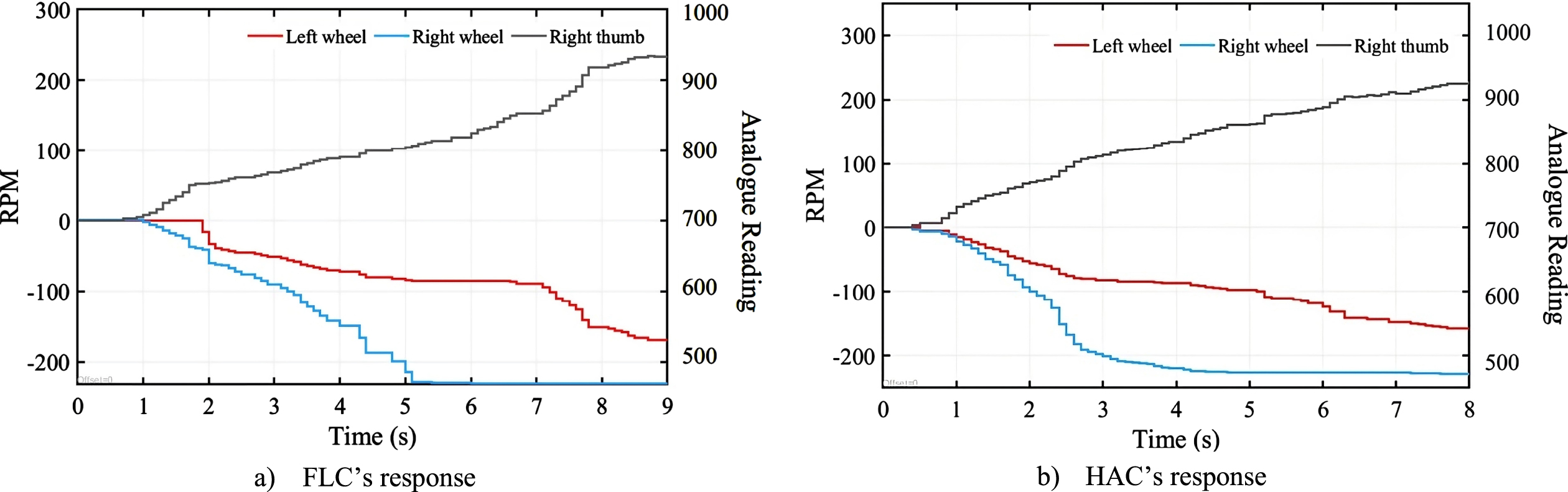
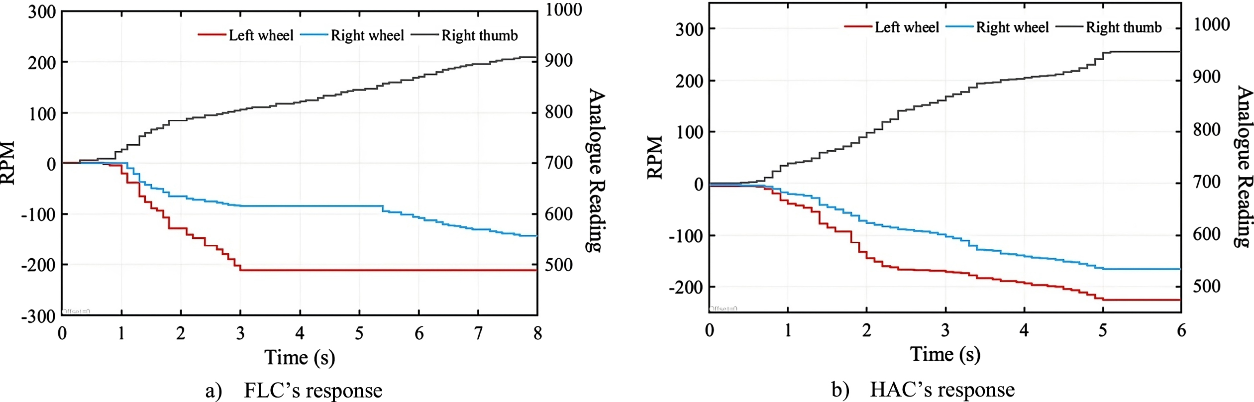
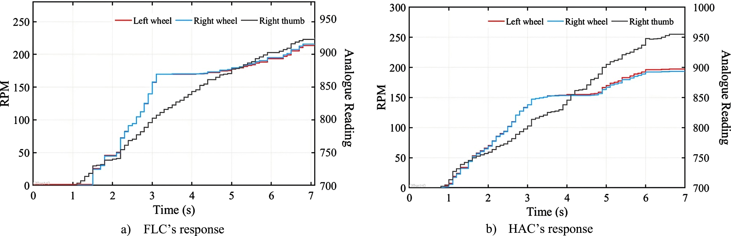
For the purpose of evaluating the suggested technique, HAC experimental results are compared to those of a fuzzy conventional controller. Figures 8 to 13 depict the following movement states: forward left, forward right, forward, backward left, backward right, and backward. Figures 14 to 17 depict the reaction of the fingers in the following order: left thumb finger, left index finger, right index finger, and right thumb. The exam requires guessing the input signals, analog reading, controller output, and wheel speed.
The response of the controller in the case of the robot turning left.
The response of the controller in the case of the robot turning right.
The response of the controller in the case of the robot moving forward.
The response of the controller in the case of the robot moving back left.
The response of the controller in the case of the robot moving back right.
The response of the controller in the case of the robot moving back.
The response of the left thumb finger.
The response of the left index finger.
The response of the right index finger.
The response of the right thumb finger.
In the instance of the robot making a left turn, all indexes are straight (N). Adjusting the two thumb fingers to merge progressively at the same rate. Unless there is a minor change in the last step, Fig. 8. depicts an identical analog reading for both thumbs. It may be seen that the HAC reacts rapidly to any input changes. The HAC data grows gradually and correlates to the analog reading’s growth. In contrast, the FLC does not answer until 0.7 seconds have passed. In addition, the FLC exhibits an erratic reaction between 4.5 and 5.4 seconds.
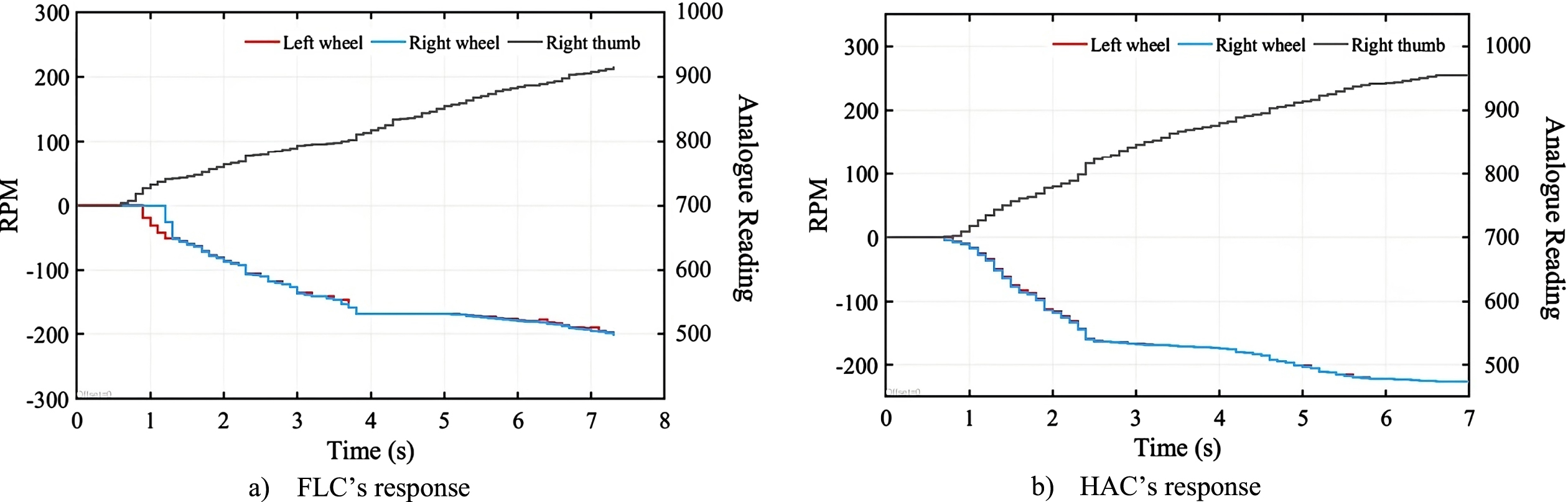
To control the right-turning of the robot, two indexes and the left thumb remain in the middle position (W). Figure 11 depicts the behavior of speed wheels in response to analog inputs. Negative numbers imply the robot is moving in the opposite direction. Observations reveal that the FLC reacts only after about 0.6s and that the right-wheel speed fluctuates significantly between 4.4 and 5.5 s. In addition, the speed of both the left and right wheels is lower than the HAC values for almost the entire sample time, despite the fact that both techniques end at the same speed of 4.8 s.
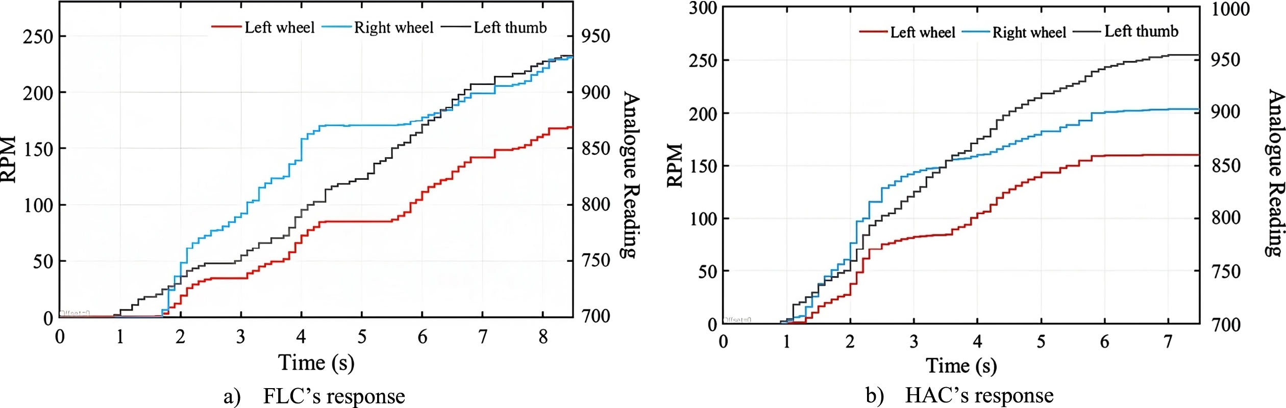
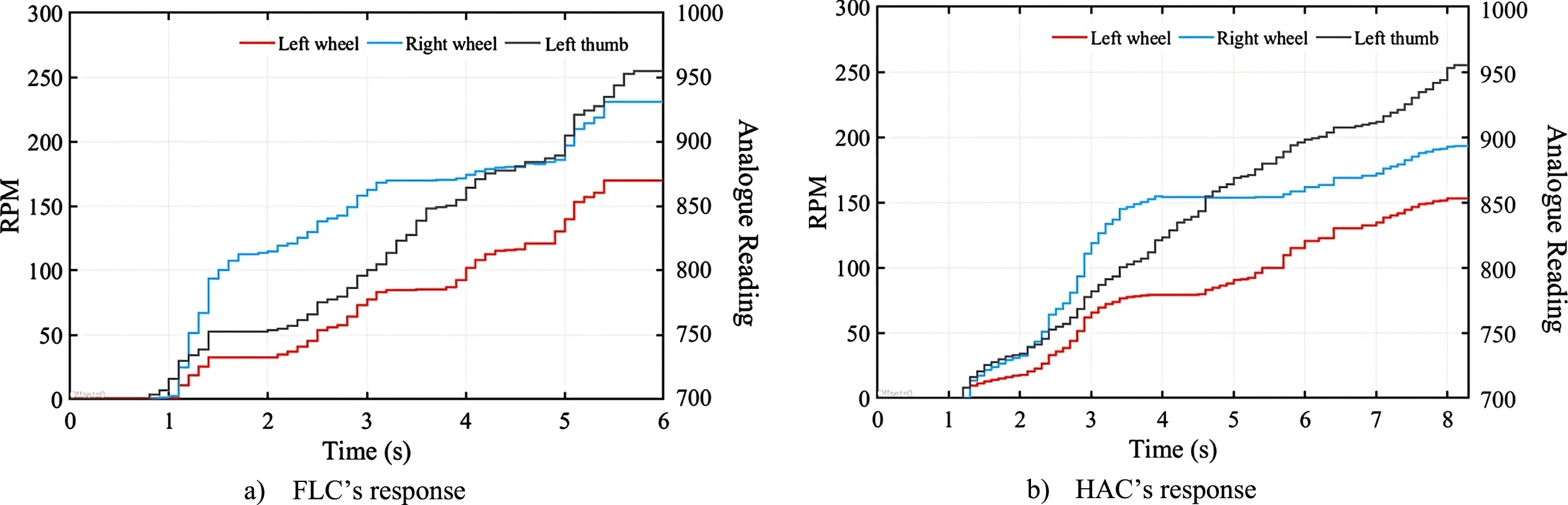
The straightening of the left index finger (position N), the contraction of the two index fingers (position P), and the progressive bending of the original right thumb in the straightening position will lead the robot to go ahead straight. The outcome is shown in Fig. 10. A comparison of HAC and FLC findings reveals that the HAC reacts instantly to a change in analog reading, but the FLC responds after about 1.0 s for the left wheel and 0.3 s for the right wheel. Moreover, despite the fact that the analog readings continue to increase progressively, the wheel speed remains almost static between 2.1 s and 3.1 s for the left-wheel speed and after 4.1 s for both wheel speeds. Moreover, the HAC data reveals that within the first 1.8 s, the difference between the two analog inputs is negligible, and the speeds of both wheels are quite near. Then, the right index’s analog reading climbs quicker than the left, resulting in the right wheel moving at a faster rate.
When the left thumb and right index finger are folded when the left index finger is straight (N position) and the left thumb is first straightened before progressively curving, the robot will move to the left. Figure 11 depicts the behavior of speed wheels in response to analog inputs. Negative numbers imply the robot is moving in the opposite direction. It is noticed that the FLC reacts only after about 0.6 s and that the right-wheel speed fluctuates significantly between 1 s and 5 s. HAC has a faster and more consistent reaction across the whole control process.
When attempting to turn the robot to the right, the same finger motions are utilized as when rotating it to the left. However, the left index is significantly bent (W position), and the right thumb is modified to blend at a slower rate. Since the difference between analog inputs is there from the start of the experiment, the HAC instantly displays the difference in speed between two wheels (Fig. 12).
For the robot to move in reverse, all fingers must be retracted, and the thumb must progressively curl. Figure 13 depicts the reaction of the left and right cakes in 6 seconds. The system response for FLC is delayed by 0.6 seconds. The left wheel of the FLC achieves its maximum value at 3 s, while the value of flex increases. The right wheel of the FLC does not satisfy the linearity of flex between 3 s and 5.3 s. HAC reacts linearly to the flex sensor’s linearity and offers a smooth response throughout the control process.
The reaction of the fingers is shown in Figs. 14 to 17 to evaluate the efficacy of the control code. During the evaluation, the fingers are first straightened and then progressively bent.
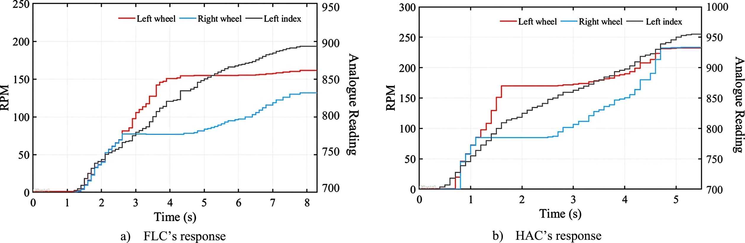
Figure 14 depicts the control effect of the left thumb. The robot will turn to the left if the left index finger and right index finger are in the straightened position (N position) and the right thumb is bent at the same angle as the left thumb. At 1.3 s to 2 s and 3.1 s to 3.8 s, FLC looks unresponsive, although the flex sensor shows a steady change. HAC demonstrates a robust reaction when there is no lag in the input signal and reacts constantly to finger movements.
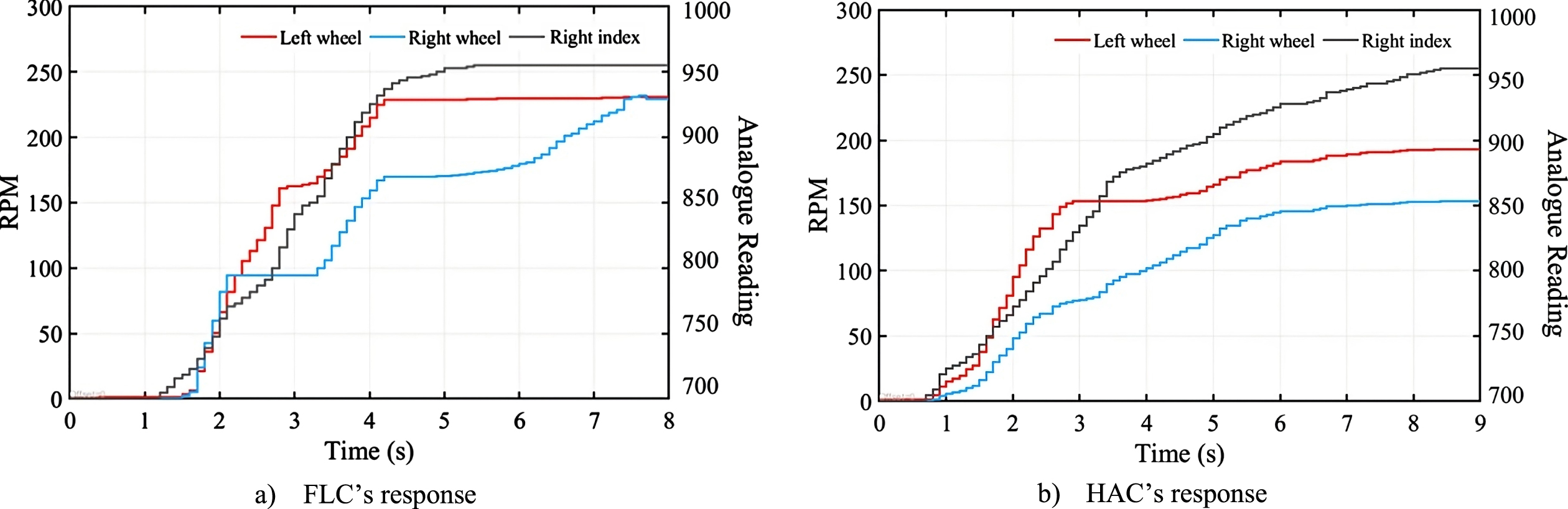
Figure 15 depicts the reaction of the index finger on the left hand. The robot will turn to the right if the left thumb is slightly bent (W position) and the right index finger and right thumb are bent concurrently with the left index finger. Figure 16 illustrates the right index finger’s reaction. In this example, the robot will turn to the right because the left thumb is somewhat bent, the left index finger is strongly curled, and the left thumb is curved according to the curvature of the right index finger. Figure 17 represents the outcome of the index finger. Since the robot’s fingers are all in a slightly curved position (W position), it will move in a straight line.
To inspect the performance of the proposed controller, the accleration of two wheels are measured and displayed as in Figs. 18 and 19. It is evident that in the case of the mobile robot turning left, the HAC controller generates a fast, smooth, and quite accurate response to the constant curvature changes from the fingers. Meanwhile, the FLC controller responds with low latency and even has no response for a certain period of time (3.8 s –4.8 s). Similarly, in the case of the robot moving to the right, the FLC controller also exhibits a poorer response to the constant signal from the sensor on the fingers and even a missing response for some period of time (3.3 s–4.4 s and 7 s–9 s). Meanwhile, the HAC controller responds faster and ensures continuity during the control process.
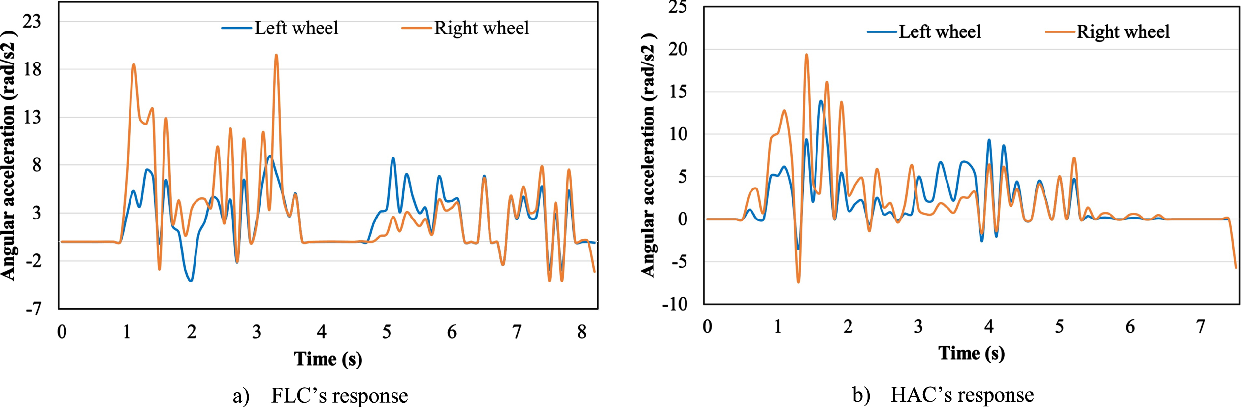
The angular acceleration (turning left).
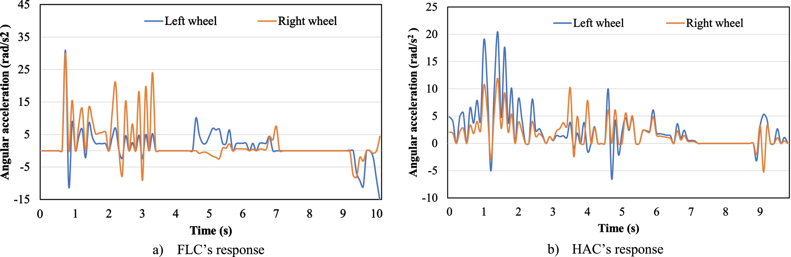
The angular acceleration (turning right).
This paper presents an improved algorithm for controlling the movement of mobile robots. Combining finger motion data and the hedge algebras algorithm, the proposed method achieves highly efficient and effective control. Input signals are received from flex sensors, which serve as the controller’s input. These signals are utilized to generate control forces based on a rule table. By incorporating Hedge Algebras, the process of generating control rules is significantly streamlined, resulting in increased precision and efficiency. The experimental findings demonstrate that the proposed method for controlling the movement of mobile robotics is effective. The system’s low latency and quick response provide significant advantages over conventional fuzzy controllers. In addition, the study demonstrates the superiority of the new control method over the conventional fuzzy controller. This innovative technology expands engineers’ remote design and control options for robotic systems, paving the way for more versatile and complex applications. Regarding future prospects, the research proposes a concentration on improving input parameters to further expedite the controller’s response time and reduce interference in the system’s communication channels. By doing so, the overall performance and adaptability of the system will be substantially enhanced, creating thrilling opportunities for implementation in various robotic applications. This research promises to contribute to the advancement of automation and control technologies and represents a significant advancement in the field of mobile robotics.